R&G CR0076BK User manual

Page 1of 9 CR0076BK
R&G
Unit 1, Shelley’s Lane, East Worldham, Alton, Hampshire, GU34 3AQ
Tel: +44 (0)1420 89007 Fax: +44 (0)1420 87301 www.rg-racing.com Email: info@rg-
racing.com
FITTING INSTRUCTIONS FOR CR0076BK OFFSET COTTON REELS
HONDA CBR 500R 2019-
THIS KIT CONTAINS THE ITEMS PICTURED AND LABELLED BELOW.
DO NOT PROCEED UNTIL YOU ARE SURE ALL PARTS ARE PRESENT.
Please note that the way the kit is packed does not necessarily represent the way of mounting to the bike
THE PARTS SHOWN MAY BE REPRESENTATIVE ONLY (FOR CLARITY OF INSTRUCTIONS ONLY)
LEFT HAND SIDE RIGHT HAND SIDE
LEGEND
ITEM 1 = M10 Flat cap (NC0010) (x2).
ITEM 2 = M10 x 45mm Long Cap Head Bolts (x2).
ITEM 3 = M10 Washers (x2).
ITEM 4 = Paddock Stand Bobbins (B0443 C/W CS303) (x2).
ITEM 5 = Left Hand Side Paddock Stand Cotton Reel Mounting Block (M0588) (x1).
ITEM 6 = Right Hand Side Paddock Stand Cotton Reel Mounting Block (M0589) (x1).
2
1
2
3
3
1
4
4
5
6

Page 2of 9 CR0076BK
R&G
Unit 1, Shelley’s Lane, East Worldham, Alton, Hampshire, GU34 3AQ
Tel: +44 (0)1420 89007 Fax: +44 (0)1420 87301 www.rg-racing.com Email: info@rg-
racing.com
Please note that in cases where kits are packed with rubber washers holding the components onto the bolt –the
rubber washers should be thrown away!
GENERAL TORQUE SETTINGS
M4 BOLT = 8Nm
M5 BOLT = 12Nm
M6 BOLT = 15Nm
M8 BOLT = 20Nm
M10 BOLT = 40Nm
TOOLS REQUIRED
•Set of Metric Allen keys to include 8mm A/F.
•Socket Set to include 19 and 24mm sockets and wrenches.
PICTURE 1 PICTURE 2
Please read all instructions before commencing fitting
FITTING INSTRUCTIONS
•Raise the rear of the bike using a paddock stand fitted with cups whilst supporting the rear wheel (suggest using
blocks of wood) to prevent the wheel from dropping when rear spindle is removed.
•Undo the rear spindle nut.
•Remove the original rear spindle.
•Remove the original chain adjuster blocks.
•Place the new left-hand adjuster block/cotton reel mount (item 5) onto the rear wheel spindle as original.
•Slide spindle through the left-hand side of the swing arm, rear wheel, brake calliper and right-hand side of the
swing arm.
•Place the remaining adjuster block/cotton reel mount (item 6) over the exposed spindle and into adjuster slot on
the right-hand side.
•Refit the spindle washer and nut and tighten according to the manufacturers recommended torque settings and
check chain adjustment.
Left Side (as you sit on bike)
•Place one of the M10 washers (item 3) onto one of the M10 bolts (item 2) as shown in picture 1.
•Place this bolt with washer through one of the cotton reels (item 4) as shown in picture 1.
•Offer this assembly into the threaded hole in the new adjuster block (as shown in picture 1) and tighten.
•Press one of the blanking caps (item 1) into the bolt head.

Page 3of 9 CR0076BK
R&G
Unit 1, Shelley’s Lane, East Worldham, Alton, Hampshire, GU34 3AQ
Tel: +44 (0)1420 89007 Fax: +44 (0)1420 87301 www.rg-racing.com Email: info@rg-
racing.com
Right Side (as you sit on bike)
•Place the remaining M10 washer (item 3) onto the remaining M10 bolt (item 2) as shown in picture 2.
•Place this bolt with washer through the remaining cotton reel (item 4) as shown in picture 2.
•Offer this assembly into the threaded hole in the new adjuster block (as shown in picture 2) and tighten.
•Press one of the blanking caps (item 1) into the bolt head.
Please ensure no parts of the paddock stand bobbins or paddock stand can contact any parts of the motorcycle when in
operation or contact any part of the motorcycle when being ridden (special care should be taken with after-market parts).
Digital copies of these instructions are available to download from www.rg-racing.com
ISSUE 1 11/07/2019 (NSY)
CONSUMER NOTICE
The catalogue description and any exhibition of samples are only broad indications of the Products and R&G may make design changes which do not
diminish their performance or visual appeal and supplying them in such state shall conform to the order. The Buyer acknowledges no representation or
warranty (other than as to title) has been given or will apply to the Products other than those in R&G’s order or confirmation and the Buyer confirms it
has chosen the Products as being of merchantable quality and suitable for its particular purposes. Where R&G fits the Products or undertakes other
services it shall exercise reasonable skill and care and rectify any fault free of charge unless the workmanship has been disturbed. The Buyer is
responsible for ensuring that the warranty on the motorcycle is not affected by the fitting of the Products. On return of any defective Products R&G
shall at its option either supply a replacement or refund the purchase money but shall not be liable if the Products have been modified or used or
maintained otherwise than in accordance with R&G’s or manufacturer’s instructions and good engineering practice or if the defect arises from accident
or neglect. Other than identified above and subject to R&G not limiting its liability for causing death and personal injury, it shall not be liable for
indirect or consequential loss and otherwise its liability shall be limited to the amounts paid by the Buyer for the Products or the fitting or service
concerned. These terms do not affect the Buyer’s statutory rights.
R&G RACING RETURNS POLICY (NON-FAULTY GOODS)
Returns must be pre-authorised (if not pre-authorised the return will be rejected). Goods may only be returned direct to us if they were purchased direct
from us (customer must prove if necessary). Otherwise to be returned to original vendor. Goods must be in re-sellable condition, in the opinion of R&G
Racing. All returns are subject to a 25% restocking and handling fee (25% of the gross value exc. P&P –at the prevailing price at time of purchase). The
customer must pay any and all carriage charges. No returns of discontinued products, unless within 14 days of purchase. This policy does not affect your
statutory rights and does not refer to faulty goods.

Page 4of 9 CR0076BK
R&G
Unit 1, Shelley’s Lane, East Worldham, Alton, Hampshire, GU34 3AQ
Tel: +44 (0)1420 89007 Fax: +44 (0)1420 87301 www.rg-racing.com Email: info@rg-
racing.com
MONTAGEANLEITUNG FÜR CR0076BK MONTAGESTÄNDERAUFNAHMEN
HONDA CBR 500R 2019-
ALLE TEILE SIND UNTEN ABGEBILDET UND GEKENNZEICHNET. BEVOR SIE MIT DER
MONTAGE BEGINNEN, ÜBERPRÜFEN SIE, DASS ALLE TEILE VORHANDEN SIND.
Hinweis: Die Verpackung der Teile stellt nicht die Reihenfolge der Montage dar.
DIE UNTEN ABGEBILDETEN TEILE DIENEN LEDIGLICH ZUR ERKLÄRUNG
LINKE SEITE RECHTE SEITE
LIEFERUMFANG
ARTIKEL 1 = M10 flache Kappe (NC0010) (x2)
ARTIKEL 2 = M10 x 45mm Inbusschrauben (x2)
ARTIKEL 3 = M10 Unterlegscheiben (x2)
ARTIKEL 4 = Paddock Montageständeraufnahmen (Bobbins) (B0443 C/W CS303) (x2)
ARTIKEL 5 = Montageblock für Montageständeraufnahme linke Seite (M0588) (x1)
ARTIKEL 6 = Montageblock für Montageständeraufnahme rechte Seite (M0589) (x1)
2
1
3
3
4
4
5
6

Page 5of 9 CR0076BK
R&G
Unit 1, Shelley’s Lane, East Worldham, Alton, Hampshire, GU34 3AQ
Tel: +44 (0)1420 89007 Fax: +44 (0)1420 87301 www.rg-racing.com Email: info@rg-
racing.com
Hinweis für Kits mit Plastikunterlegscheiben an den Schrauben –Diese Plastikunterlegscheiben werden nicht
für den Einbau benötigt!
ALLGEM.ANZUGSDREHMOMENTE
M4 SCHRAUBE = 8Nm
M5 SCHRAUBE = 12Nm
M6 SCHRAUBE = 15Nm
M8 SCHRAUBE = 20Nm
M10 SCHRAUBE = 40Nm
SIE BENÖTIGEN FOLGENDES WERKZEUG
•Satz Inbusschlüssel inkl. 8mm A/F Inbusschlüssel
•Satz Steckschlüssel inkl. 19 und 24mm Steckschlüssel
ABBILDUNG 1 ABBILDUNG 2
Bitte die Montageanleitung komplett durchlesen, bevor Sie mit der Montage beginnen.
MONTAGEANLEITUNG
•Benutzen Sie einen Rennsport-Montageständer, um das Heck aufzubocken - das Hinterrad dabei stützen (wir
empfehlen Holzblöcke), um zu vermeiden, dass das Rad runterfällt, wenn die hintere Radachse entfernt wird.
•Lösen Sie die hintere Achsmutter.
•Entfernen Sie die hintere Radachse.
•Entfernen Sie die original Kettenspannerplatten.
•Die neue verstellbare Halteplatte/Montageplatte für die linke Seite (Artikel 5) an der hinteren Radachse
anbringen wie ursprünglich wieder.
•Schieben Sie die Achse von der linken Seite in die Schwinge, durch das Hinterrad, den Bremssattel und die
rechte Seite der Schwinge.
•Die übrige verstellbare Halteplatte/Montageplatte (Artikel 6) über die hervorstehende Achse in die Schwinge an
der rechten Seite einsetzen.
•Montieren Sie die Unterlegscheibe und Mutter wieder und ziehen Sie sie mit dem vom Hersteller empfohlenen
Anzugsdrehmoment fest. Kontrollieren Sie die Kettenspannung.
Linke Seite (in Fahrtrichtung)
•Eine M10 Unterlegscheibe (Artikel 3) an einer M10 Schraube (Artikel 2) anbringen –siehe Abbildung 1.
•Die Schraube mit Unterlegscheibe durch eine Montageständeraufnahme (Artikel 4) führen, wie in Abbildung 1
abgebildet.

Page 6of 9 CR0076BK
R&G
Unit 1, Shelley’s Lane, East Worldham, Alton, Hampshire, GU34 3AQ
Tel: +44 (0)1420 89007 Fax: +44 (0)1420 87301 www.rg-racing.com Email: info@rg-
racing.com
•Die Einheit in die Gewindebohrung im neuen Montageblock einführen (wie in Abbildung 1 abgebildet) und
befestigen.
•Eine flache Kappe (Artikel 1) in den Schraubenkopf einsetzen.
Rechte Seite (in Fahrtrichtung)
•Die übrige M10 Unterlegscheibe (Artikel 3) an der übrigen M10 Schraube (Artikel 2) anbringen –siehe
Abbildung 2.
•Diese Schraube mit Unterlegscheibe durch die übrige Montageständeraufnahme (Artikel 4) führen, wie in
Abbildung 2 abgebildet.
•Die Einheit in die Gewindebohrung im neuen Montageblock einführen (wie in Abbildung 2 abgebildet) und
befestigen.
•Eine flache Kappe (Artikel 1) in den Schraubenkopf einsetzen.
Bitte stellen Sie sicher, dass keine Teile der Montageständeraufnahmen / des Rennsport-Montageständers mit anderen
Teilen des Motorrades in Berührung kommen (dies ist besonders wichtig bei Teilen aus dem Zubehörmarkt). Fahren Sie
nicht mit dem Motorrad bis dies sorgfältig überprüft wurde.
Eine digitale Version dieser Montageanleitung kann auf folgender Seite heruntergeladen werden: www.rg-racing.com
AUSGABE 1 11/07/2019 (NSY)

Page 7of 9 CR0076BK
R&G
Unit 1, Shelley’s Lane, East Worldham, Alton, Hampshire, GU34 3AQ
Tel: +44 (0)1420 89007 Fax: +44 (0)1420 87301 www.rg-racing.com Email: info@rg-
racing.com
NOTICE DE MONTAGE POUR CR0076BK PROTECTION CRASH
HONDA CBR 500R 2019-
Le kit contient les articles exposés ci-dessous, vérifier que toutes les pièces
soient présentes avant de procéder au montage.
La façon dont le kit est emballé ne correspond pas forcément à la façon de
monter les pièces sur la moto.
LES PARTIES PRESENTEES PEUVENT ETRE UNIQUEMENT REPRÉSENTATIVES (POUR LA CLARTÉ DES
INSTRUCTIONS UNIQUEMENT)
CÔTÉ GAUCHE CÔTÉ DROIT
LÉGENDE
ARTICLE 1 = M10 Capuchon plat (NC0010) (x2).
ARTICLE 2 = M10 x 45mm Boulons (x2).
ARTICLE 3 = M10 Rondelles (x2).
ARTICLE 4 = Bobines de béquille de stand (B0443 C/W CS303) (x2).
2
1
2
3
3
1
4
4
5
6

Page 8of 9 CR0076BK
R&G
Unit 1, Shelley’s Lane, East Worldham, Alton, Hampshire, GU34 3AQ
Tel: +44 (0)1420 89007 Fax: +44 (0)1420 87301 www.rg-racing.com Email: info@rg-
racing.com
ARTICLE 5 = Bloc de montage de bobine de béquille de stand côté gauche (M0588) (x1).
ARTICLE 6 = Bloc de montage de bobine de béquille de stand côté droit (M0589) (x1).
Notez que si les kits sont emballés avec des rondelles en caoutchouc servant à tenir les composants, ces
rondelles doivent être jetées!
VALEURS DE SERRAGE MAXIMALES
M4 BOULON = 8Nm
M5 BOULON = 12Nm
M6 BOULON = 15Nm
M8 BOULON = 20Nm
M10 BOULON = 40Nm
OUTILS REQUIS
•Clés Allen 8mm.
•Clé à cliquet + douilles 19 et 24mm.
PHOTO 1 PHOTO 2
Lire l’ensemble de la notice avant de procéder au montage
NOTICE DE MONTAGE
•Soulevez l'arrière de la moto à l'aide d'un support béquille avec bonnets tout en soutenant la roue arrière
(suggérez d'utiliser des blocs de bois) pour éviter que la roue ne tombe lorsque vous retirez le moyeu arrière.
•Desserrer l'écrou de moyeu arrière.
•Retirez le moyeu arrière d'origine.
•Retirez les blocs de réglage de la chaîne d'origine.
•Placez le nouveau bloc de réglage gauche / support de dévidoir (article 5) sur le moyeu de la roue arrière
comme à l'origine.
•Faites glisser le moyeu par le côté gauche du bras oscillant, la roue arrière, l’étrier de frein et le côté droit du
bras oscillant.
•Placez le support de bloc de réglage / bobine de restante (article 6) sur le moyeu exposé et dans la fente de
réglage du côté droit.
•Remontez la rondelle et l'écrou de le moyeu puis serrez-les selon les couples recommandés, puis vérifiez le
réglage de la chaîne.

Page 9of 9 CR0076BK
R&G
Unit 1, Shelley’s Lane, East Worldham, Alton, Hampshire, GU34 3AQ
Tel: +44 (0)1420 89007 Fax: +44 (0)1420 87301 www.rg-racing.com Email: info@rg-
racing.com
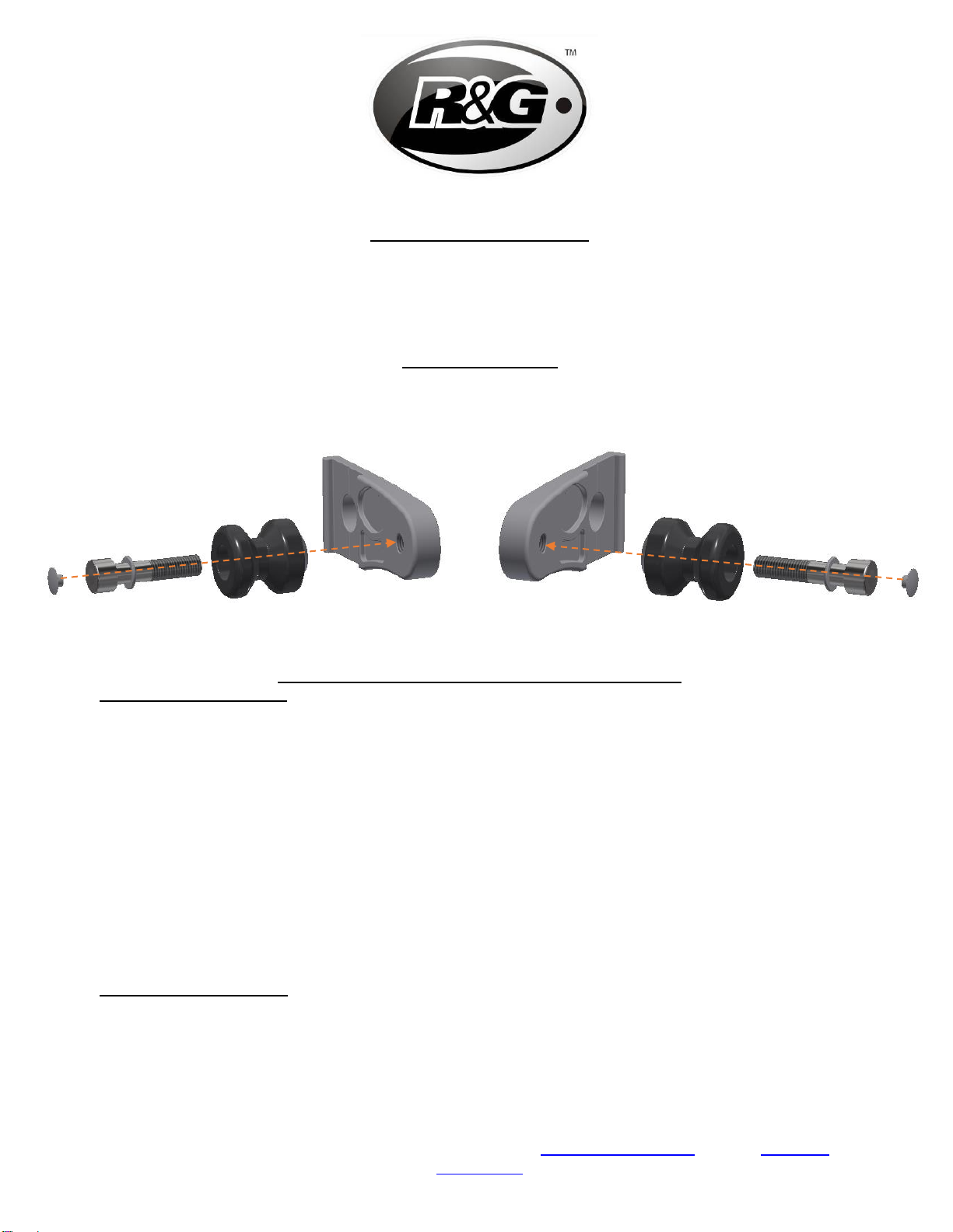
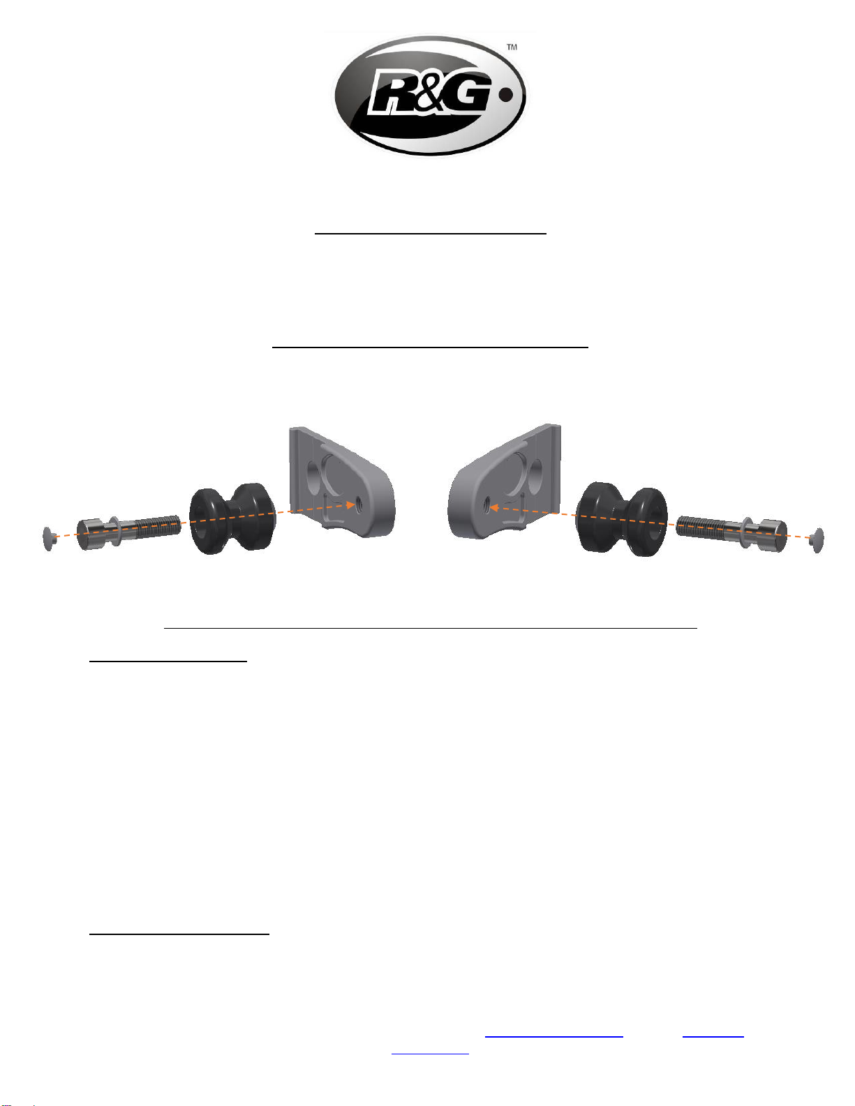
Côté gauche (lorsqu’on est assis sur la moto)
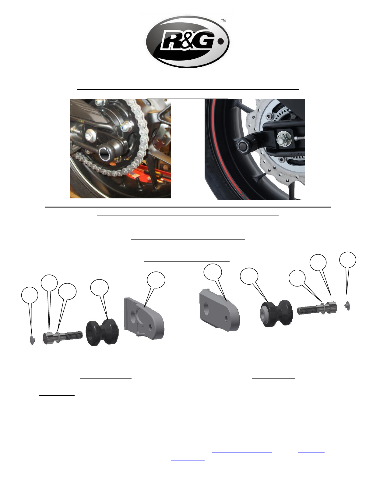
•Placez l’une des rondelles M10 (article 3) sur l’un des boulons M10 (article 2) comme indiqué sur la photo 1.
•Placez ce boulon avec la rondelle dans l’une des bobines (article 4) voir photo 1.
•Montez l’ensemble dans le trou fileté du nouveau bloc de réglage (comme indiqué sur la photo 1) et serrez.
•Enfoncez l'un des capuchons d'obturation (article 1) dans la tête du boulon.
Côté droit (lorsqu’on est assis sur la moto)
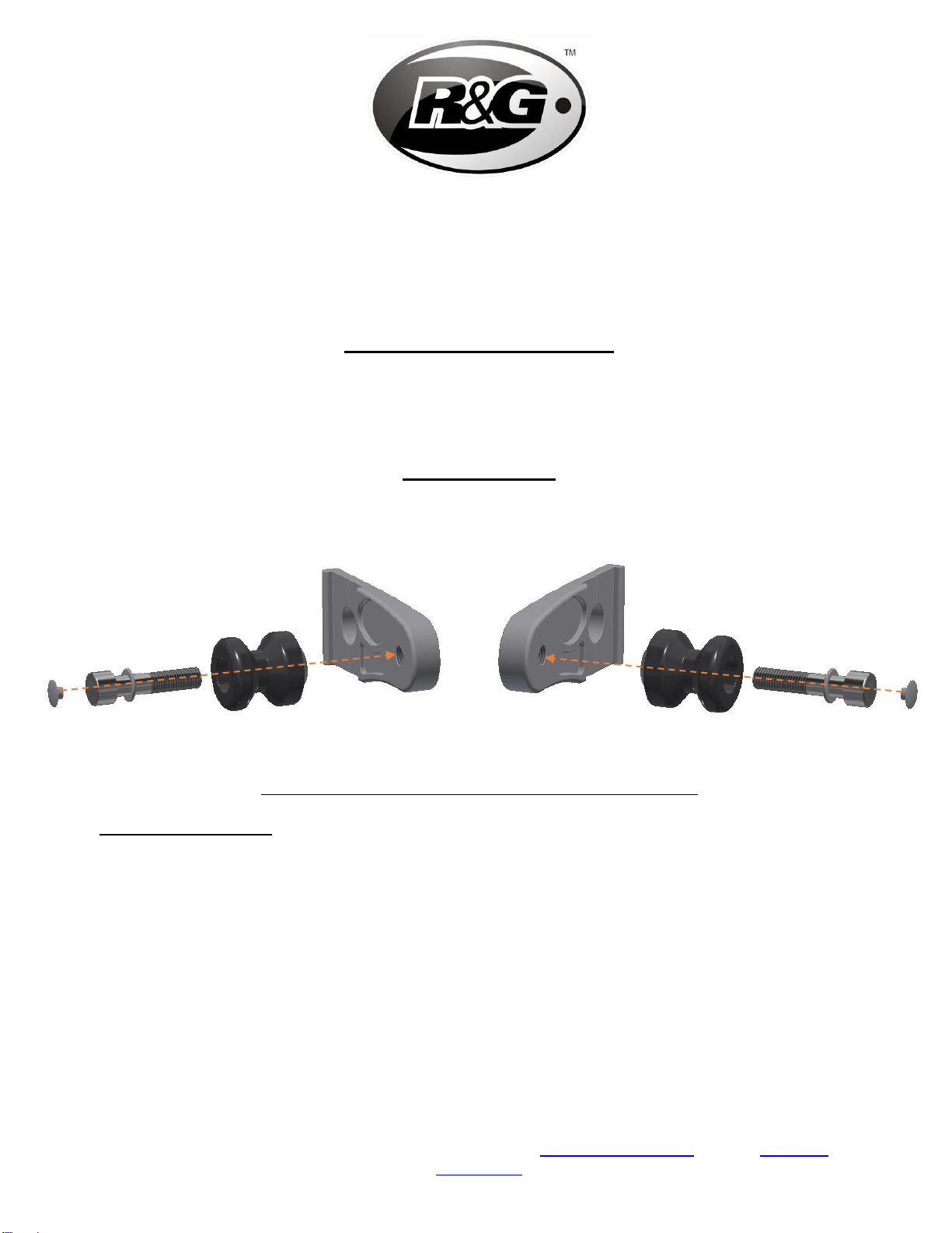
•Placez la rondelle M10 restante (article 3) sur le boulon M10 restant (article 2) comme indiqué sur la photo 2.
•Placez ce boulon avec une rondelle à travers la protection restante (article 4), comme indiqué sur la photo 2.
•Monter l’ensemble dans le trou fileté du nouveau bloc de réglage (comme indiqué sur la photo 2) et serrez.
•Enfoncez l'un des capuchons d'obturation (article 1) dans la tête du boulon.
Veuillez-vous assurer qu'aucune partie des protections ne puisse être contact avec une autre partie de la moto lorsqu'elle
est en fonctionnement (un soin particulier doit être apporté aux pièces de rechange).
Notice disponible au téléchargement sur www.rg-racing.com
ISSUE 1 11/07/2019 (NSY)
CONSUMER NOTICE
The catalogue description and any exhibition of samples are only broad indications of the Products and R&G may make design changes which do not
diminish their performance or visual appeal and supplying them in such state shall conform to the order. The Buyer acknowledges no representation or
warranty (other than as to title) has been given or will apply to the Products other than those in R&G’s order or confirmation and the Buyer confirms it
has chosen the Products as being of merchantable quality and suitable for its particular purposes. Where R&G fits the Products or undertakes other
services it shall exercise reasonable skill and care and rectify any fault free of charge unless the workmanship has been disturbed. The Buyer is
responsible for ensuring that the warranty on the motorcycle is not affected by the fitting of the Products. On return of any defective Products R&G
shall at its option either supply a replacement or refund the purchase money but shall not be liable if the Products have been modified or used or
maintained otherwise than in accordance with R&G’s or manufacturer’s instructions and good engineering practice or if the defect arises from accident
or neglect. Other than identified above and subject to R&G not limiting its liability for causing death and personal injury, it shall not be liable for
indirect or consequential loss and otherwise its liability shall be limited to the amounts paid by the Buyer for the Products or the fitting or service
concerned. These terms do not affect the Buyer’s statutory rights.
R&G RACING RETURNS POLICY (NON-FAULTY GOODS)
Returns must be pre-authorised (if not pre-authorised the return will be rejected). Goods may only be returned direct to us if they were purchased direct
from us (customer must prove if necessary). Otherwise to be returned to original vendor. Goods must be in re-sellable condition, in the opinion of R&G
Racing. All returns are subject to a 25% restocking and handling fee (25% of the gross value exc. P&P –at the prevailing price at time of purchase). The
customer must pay any and all carriage charges. No returns of discontinued products, unless within 14 days of purchase. This policy does not affect your
statutory rights and does not refer to faulty goods.
Table of contents
Languages:
Other R&G Motorcycle Accessories manuals
Popular Motorcycle Accessories manuals by other brands

Ops-Core
Ops-Core FAST LOW PROFILE BALLISTIC APPLIQUÉ Operator's manual

Thunderbike
Thunderbike Titanium manual

SCHUBERTH
SCHUBERTH SR1 manual

Paaschburg & Wunderlich
Paaschburg & Wunderlich HIGHSIDER FLIGHT Instruction and installation manual

Datatool
Datatool system 3 user guide

hepco & becker
hepco & becker 6304567 00 01 quick start guide