R&G LP0339BK Install guide

Page 1of 27 LP0339
LP0339BK FITTING INSTRUCTION
This kit contains the items pictured and labelled over page.
Some parts may be shown for clarity of instructions only.
Do not proceed until you are sure all parts are present.
Please read all instructions before proceeding.
IF IN ANY DOUBT WHEN FITTING OUR PRODUCTS, CONSULT ONE
OF OUR DEALERS OR HAVE FITTED BY AQUALIFIED TECHNICIAN.
Please note that the way the kit is packed does not necessarily represent the way of
mounting to the bike.
In the event of rubber washers being used to hold components onto bolts,
these rubber washers can be thrown away.
DIGITAL COPIES OF THESE INSTRUCTIONS ARE AVAILABLE FROM
WWW.RG-RACING.COM

Page 2of 27 LP0339
LEGEND
TOOLS REQUIRED
• Set of metric Allen keys.
• Phillip Screwdriver
• Metric Socket set.
• Electrical pliers/crimps
GENERAL TORQUE SETTINGS
M4 BOLT = 8Nm
M5 BOLT = 12Nm
M6 BOLT = 15Nm
M8 BOLT = 20Nm
M10 BOLT = 40Nm
M12 BOLT = 40Nm
ITEM No.
DESCRIPTION
QTY
ITEM 1
M6 x 50mm BUTTON HEAD BOLTS
2
ITEM 2
M6 x 15mm BUTTON HEAD BOLTS
2
ITEM 3
M6 WASHERS (16mm O/DIA)
8
ITEM 4
SPACER 35mm Long (S0795)
2
ITEM 5
SUB-FRAME (FOR ILLUSTRATION ONLY)
N/A
ITEM 6
COVER PLATE (TB0193 Pt.1)
1
ITEM 7
LICENCE PLATE BRACKET ASSEMBLY (TB0193 Pt.2)
1
ITEM 8
M6 NYLOC NUTS
4
ITEM 9
M3 NUTS
2
ITEM 10
M3 WASHERS
2
ITEM 11
TAILLIGHT SHROUD (LA0003 Shroud)
1
ITEM 12
TAILLIGHT UNIT (LA0003)
1
ITEM 13
TAILLIGHT CONNECTOR (CON0040)
1
ITEM 14
75mm LONG CABLE TIES
2
ITEM 15
300mm LONG HEAT SHRINK
2
ITEM 16
REFLECTOR
1
ITEM 17
OEM INDICATOR ADAPTORS (I0037)
1

Page 3of 27 LP0339
ASSEMBLY DIAGRAM
PICTURE 1PICTURE 2
14
13
16
15
20

Page 4of 27 LP0339
PICTURE 3 PICTURE 4
PICTURE 5 PICTURE 6
PICTURE 7 PICTURE 8

Page 5of 27 LP0339
PICTURE 9 PICTURE 10
PICTURE 11 PICTURE 12
PICTURE 13PICTURE 14
A

Page 6of 27 LP0339
PICTURE 15 PICTURE 16
FITTING INSTRUCTIONS
•Remove the seat using the key.
•Remove the four bolts that hold the seat catch as arrowed in picture 1
using 4mm Allen key. Remove the seat catch.
•Remove the two bolts that hold the tool holder as arrowed in picture 2
using 4mm Allen key. Remove the tool holder tray.
•Remove the four bolts that hold the seat lock mechanism as arrowed in
picture 3 using 4mm Allen key. Remove seat lock mechanism (It is not
necessary to detach the cable and remove the seat lock mechanism
completely)
•Disconnect the 4 electrical connectors (taillight, L/H indicator, R/H
indicator and no. plate light connectors) as arrowed in picture 4. Please
note the orientation of the connectors for re-fitting at later stage.
•Remove the 3 bolts that hold the undertray cover as arrowed in picture
5 using 5mm Allen key. Remove the undertray cover.
•Remove the four main bolts that hold the tail unit assembly as arrowed
in picture 6 using 6mm Allen key. From below, using a 6mm Allen key
hold still the four button head shape nuts while the four main bolts are
being loosen, this is to stop the nuts from turning (Arrowed in picture
7). Please keep the tail unit assembly supported during removal as it
may drop and cause damage to the wiring loom. Gently retract the
whole tail unit assembly and the wiring loom away from the sub-
frame/ bike.

Page 7of 27 LP0339
•Remove the two nuts that hold the rear OEM taillight assembly
(located on the bottom of the taillight unit) using 10mm socket and a
ratchet. Remove the OEM taillight unit.
•Remove the 5 button head bolts that hold the rear mudguard (located
on top of the mudguard) using 4mm Allen key. Remove the rear
mudguard.
•Remove the two plastic clips that secure the wire bundle (shown in
picture 8) using a suitable Phillip screwdriver.
Using the original indicators
•Remove the spreader/location plate arrowed in picture 9.
•Gently squeeze the indicator stem and remove the indicator with its
wiring.
•Repeat the procedure for the other indicator.
•Fit the original indicator to the new licence plate bracket (item 7), fit
the indicator adaptor (item 17) and re-fit the spreader to secure the
indicator in place.
•Feed the indicator wires through the centre hole of the license plate
bracket as shown in picture 10.
Fitting the Taillight
•From the kit, take the Taillight unit (Item 12) and its shroud (Item 11).
Insert the taillight into the shroud by aligning the two studs at the
back of the taillight into the two holes provided on the shroud. Mount
the whole assembly into the licence plate bracket (Item7) and secure
with M3 washers (Item 10) and M3 Nuts (Item 9). Tighten the M3 nuts
(Item 9)
•Feed the wire through the centre hole on the Licence Plate bracket
(Item 7) together with the L/H and R/H Indicator wires (Picture 10).
•Cut the Heat-shrink tube (Item 15) into a suitable length and feed the
three wires through, using a suitable heating resources, shrink the
heat-shrink tube.
•Bring the whole assembly towards the rear sub-frame of the bike
(coming from below as illustrated on the first page of this manual).
Feed all the wires through the initial hole on the left-hand side of the
OEM undertray (arrowed in Picture 12). Support the assembly onto
the sub-frame at this stage and be aware of trapped wires. Please
make sure that there is enough slack within the wires as they can get
damaged under tension.
•Mount the base cover plate (Item 6) below the licence plate bracket
assembly (Item 7) with its catch inserted into the centre hole located

Page 8of 27 LP0339
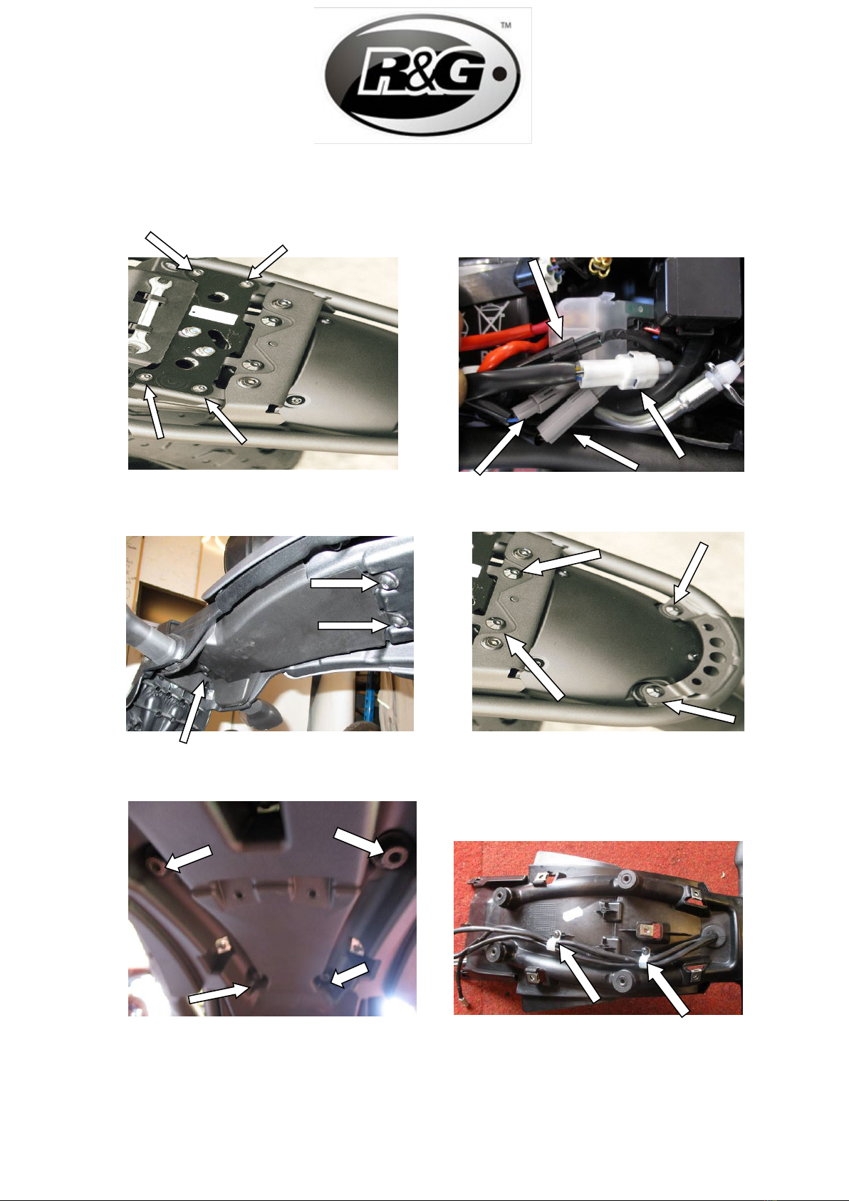
on the OEM undertray unit (Labelled A in picture 12 and arrowed in
picture 13)
•Insert the two M6 x 15mm bolts (Item 2) with M6 washers (Item 3)
through the two holes located on the back of the subframe (Arrowed in
picture 13). Secure the assembly with M6 washer (Item 3) and M6
nyloc nut (Item 8) on each bolt. Do not fully tighten the nuts at this
stage. Please make sure that the wiring is positioned in the same
orientation as shown in picture 14.
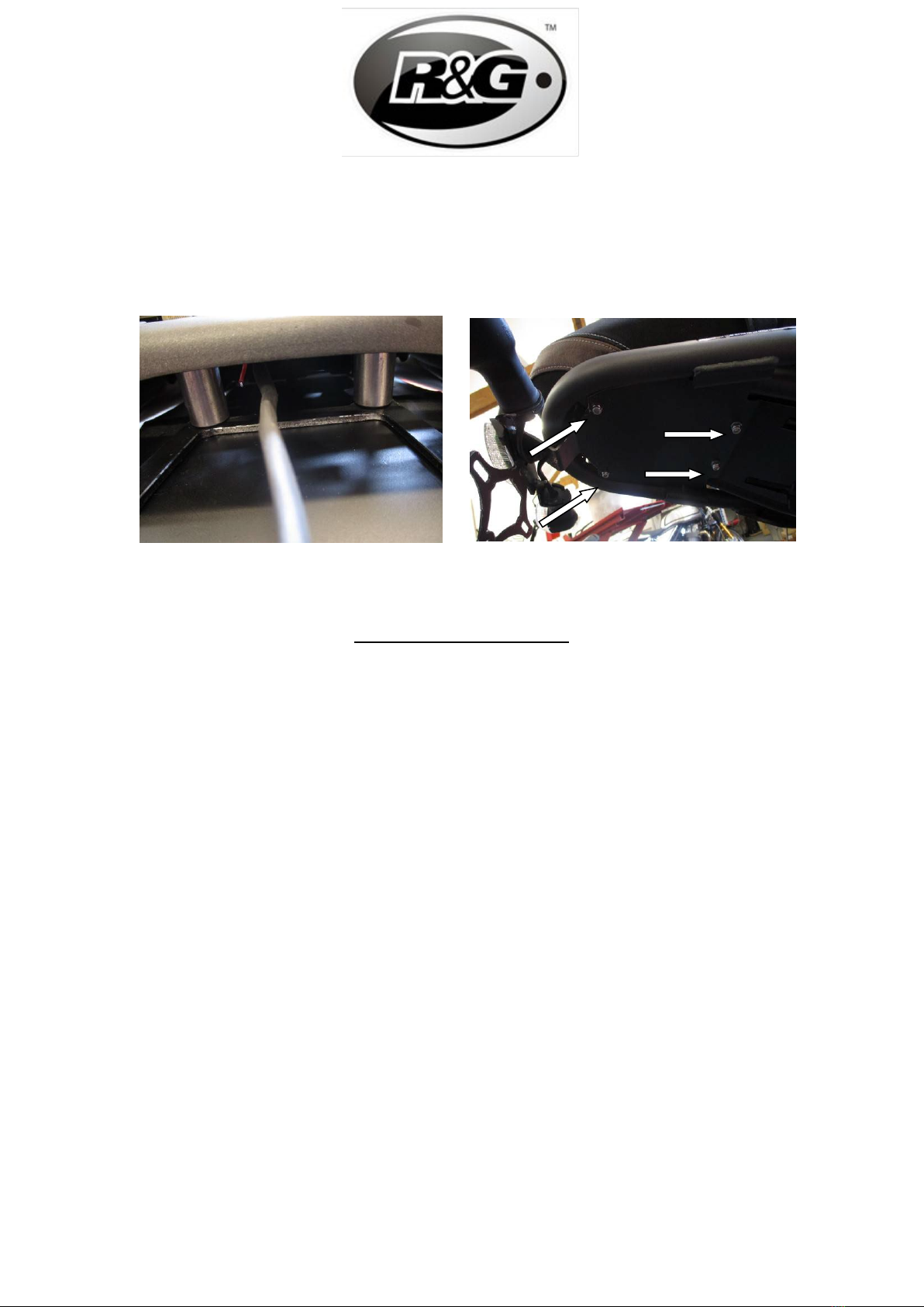
•Insert the two Spacers (Item 4) between the sub-frame and the
licence plate bracket assembly as orientated in picture 16. Insert an
M6 x 50mm bolt (Item 1) with M6 washer (Item 3) through the hole
where the spacer is aligned to on the sub-frame. Ensure the bolt is
gone through the spacer and the spacer is sandwiched between the
sub-frame and the licence plate bracket (item 7). Secure the assembly
with M6 washer (Item 3) and M6 nyloc nut (Item 8). Repeat the
procedure for the other M6 x 50mm bolt (Item 1).
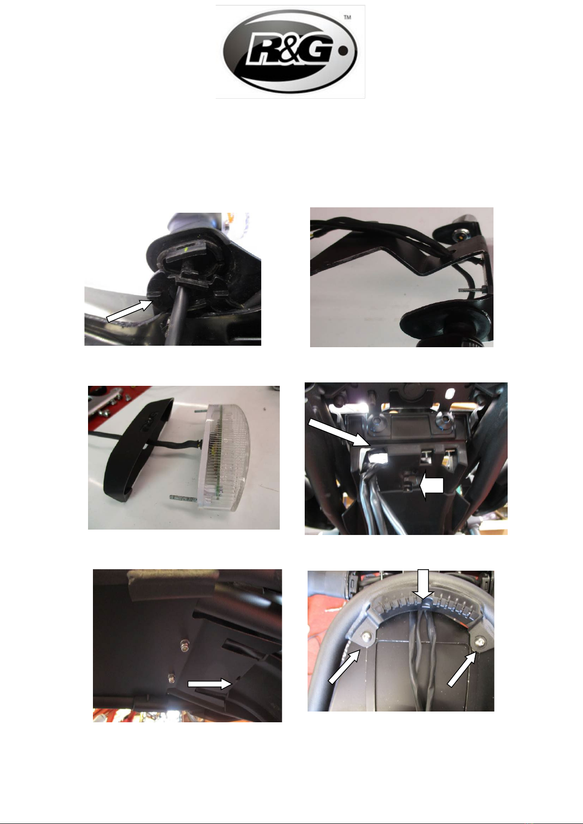
•Locate the wiring in the centre between the two spacers as shown in
picture 15.
•Tighten the four nyloc nuts using suitable tools to ±15 Nm (Picture 16)
•Reconnect all the indicator wiring plug sockets and check operation.
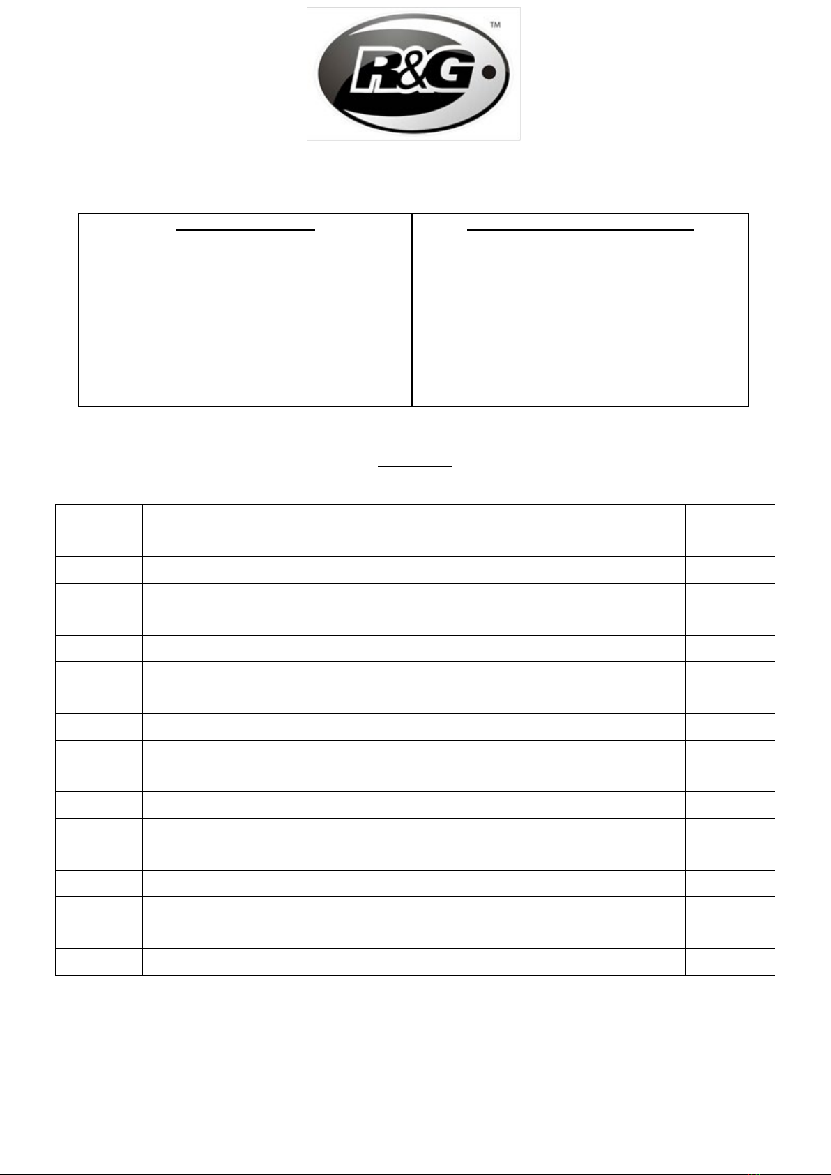
•Connect the male connector of the taillight connector (Item 13) into
the OEM female connector in the main wiring loom.
•OEM number plate connector light is no longer in use as the taillight
unit (Item 12) comes with built-in LED license plate lights.
•Fit licence plate to the new licence plate bracket (item 7) (it may
require re-drilling).
•IMPORTANT: IF FITTING A FULL-SIZE LICENCE PLATE AND
PLACING IT FAR DOWN ON THE LICENCE PLATE HANGER,
THERE IS A SMALL CHANCE OF THE LICENCE PLATE HITTING
THE BACK WHEEL UNDER HEAVY LOAD AND OVER LARGE
BUMPS IN THE ROAD. IT IS YOUR RESPONSIBILITY TO CHECK
FOR THIS POSSIBILITY AND TAKE AVOIDING ACTION.
FAILURE TO CHECK THIS COULD RESULT IN SERIOUS INJURY.
•Refit the Seat lock mechanism, tool holder and seat catch as original.
•Refit seat.
•Depending on local laws, attach enclosed red reflector (item 18) in an
appropriate location.
Please test the indicators, rear light, no. plate light and brake
light before riding.

Page 9of 27 LP0339
See more R&G products for your Motorcycle in the
link below:
R&G Racing | All Products for Yamaha - XSR700 (2022) (rg-racing.com)
ISSUE 1 15/12/2022 (JH)
ISSUE 2 16/12/2022 (JH)
CONSUMER NOTICE
The catalogue description and any exhibition of samples are only broad indications of the Products and R&G may make design
changes which do not diminish their performance or visual appeal and supplying them in such state shall conform to the order.
The Buyer acknowledges no representation or warranty (other than as to title) has been given or will apply to the Products other
than those in R&G’s order or confirmation and the Buyer confirms it has chosen the Products as being of merchantable quality
and suitable for its particular purposes. Where R&G fits the Products or undertakes other services it shall exercise reasonable
skill and care and rectify any fault free of charge unless the workmanship has been disturbed. The Buyer is responsible for
ensuring that the warranty on the motorcycle is not affected by the fitting of the Products. On return of any defective Products
R&G shall at its option either supply a replacement or refund the purchase money but shall not be liable if the Products have
been modified or used or maintained otherwise than in accordance with R&G’s or manufacturer’s instructions and good
engineering practice or if the defect arises from accident or neglect. Other than identified above and subject to R&G not limiting
its liability for causing death and personal injury, it shall not be liable for indirect or consequential loss and otherwise its liability
shall be limited to the amounts paid by the Buyer for the Products or the fitting or service concerned. These terms do not affect
the Buyer’s statutory rights.
R&G RACING RETURNS POLICY (NON-FAULTY GOODS)
Returns must be pre-authorised (if not pre-authorised the return will be rejected). Goods may only be returned direct to us if they
were purchased direct from us (customer must prove if necessary). Otherwise to be returned to original vendor. Goods must be
in re-sellable condition, in the opinion of R&G Racing. All returns are subject to a 25% restocking and handling fee (25% of the
gross value exc. P&P – at the prevailing price at time of purchase). The customer must pay any and all carriage charges. No
returns of discontinued products, unless within 14 days of purchase. This policy does not affect your statutory rights and does not
refer to faulty goods.

Page 10 of 27 LP0339
NOTICE DE MONTAGE POUR LP0339BK SUPPORT DE PLAQUE
CE KIT CONTIENT LES ARTICLES ILLUSTRES ET ETIQUETES SUR LA PAGE.
CERTAINES PARTIES PEUVENT ETRE PRESENTES UNIQUEMENT POUR LA CLARTE DES
INSTRUCTIONS.
NE PAS PROCEDER AU MONTAGE TANT QUE VOUS N'ETES PAS SUR QUE TOUTES LES
PIECES SOIENT PRESENTES.
VEUILLEZ LIRE TOUTES LES INSTRUCTIONS AVANT DE CONTINUER.
EN CAS DE DOUTE LORS DU MONTAGE DE NOS PRODUITS,
CONSULTEZ UN DE NOS REVENDEURS OU FAITES APPEL A UN
TECHNICIEN QUALIFIÉ.
VEUILLEZ NOTER QUE LA FAÇON DONT LE KIT EST EMBALLE NE REPRESENTE PAS
NECESSAIREMENT LA MANIERE DE LE MONTER SUR LA MOTO.
SI DES RONDELLES EN CAOUTCHOUC SONT UTILISEES POUR MAINTENIR LES
COMPOSANTS SUR LES BOULONS,ELLES PEUVENT ETRE JETEES.
NOTICE DISPONIBLE AU TELECHARGEMENT SUR :
WWW.RG-RACING.COM

Page 11 of 27 LP0339
LÉGENDE
OUTILS REQUIS
• Clés Allen
• Tournevis cruciforme
• Clé métrique.
• Pinces électriques
VALEURS DE SERRAGE
M4 BOULON = 8Nm
M5 BOULON = 12Nm
M6 BOULON = 15Nm
M8 BOULON = 20Nm
M10 BOULON = 40Nm
M12 BOULON = 40Nm
GEN
ARTICLE No.
DESCRIPTION
QTÉ
ARTICLE 1
M6 x 50mm BOULONS
2
ARTICLE 2
M6 x 15mm BOULONS
2
ARTICLE 3
M6 RONDELLES (16mm O/DIA)
8
ARTICLE 4
ENTRETOISE 35mm de long (S0795)
2
ARTICLE 5
SOUS CADRE (POUR ILLUSTRER UNIQUEMENT)
N/A
ARTICLE 6
PLAQUE DE COUVERTURE (TB0193 Pt.1)
1
ARTICLE 7
ASSEMBLAGE DE SUPPORT DE PLAQUE (TB0193 Pt.2)
1
ARTICLE 8
M6 ÉCROUS
4
ARTICLE 9
M3 ÉCROUS
2
ARTICLE 10
M3 RONDELLES
2
ARTICLE 11
PROTECTION FEU DE PLAQUE (LA0003 Shroud)
1
ARTICLE 12
UNITÉ DE SUPPORT DE PLAQUE (LA0003)
1
ARTICLE 13
CONNECTEUR DE FEU DE PLAQUE (CON0040)
1
ARTICLE 14
75mm COLLIERS DE SERRAGE
2
ARTICLE 15
300mm MANCHON THERMO RÉTRACTABLE
2
ARTICLE 16
RÉFLECTEUR
1
ARTICLE 17
ADAPTATEURS DE CLIGNOTANT D’ORIGINE (I0037)
1

Page 12 of 27 LP0339
SCHÉMA D’ENSEMBLE
PHOTO 1PHOTO 2
14
13
16
15
20

Page 13 of 27 LP0339
PHOTO 3 PHOTO 4
PHOTO 5 PHOTO 6
PHOTO 7 PHOTO 8

Page 14 of 27 LP0339
PHOTO 9 PHOTO 10
PHOTO 11 PHOTO 12
PHOTO 13 PHOTO 14
A

Page 15 of 27 LP0339
PHOTO 15 PHOTO 16
NOTICE DE MONTAGE
•Retirer le siège à l'aide de la clé.
•Retirez les quatre boulons qui maintiennent le loquet du siège comme indiqué par la flèche sur
la photo 1 à l'aide d'une clé Allen de 4 mm. Retirez le crochet du siège.
•Retirez les deux boulons qui maintiennent le porte-outil comme indiqué sur la photo 2 à l'aide
d'une clé Allen de 4 mm. Retirez le plateau porte-outils.
•Retirez les quatre boulons qui maintiennent le mécanisme de verrouillage du siège comme
indiqué sur la photo 3 à l'aide d'une clé Allen de 4 mm. Retirez le mécanisme de verrouillage du siège
(il n'est pas nécessaire de détacher le câble et de retirer complètement le mécanisme de verrouillage du
siège).
•Déconnectez les 4 connecteurs électriques (connecteurs feu arrière, clignotant côté gauche,
clignotant côté droit et feu de plaque) comme indiqué sur la photo 4. Veuillez noter l'orientation des
connecteurs pour un remontage ultérieur.
•Retirez les 3 boulons qui retiennent le couvercle du dessous de caisse comme indiqué sur la
photo 5 à l'aide d'une clé Allen de 5 mm. Retirer le couvercle du dessous de caisse.
•Retirez les quatre boulons principaux qui maintiennent l'ensemble de l'empennage comme
indiqué sur la photo 6 à l'aide d'une clé Allen de 6 mm. Par le bas, à l'aide d'une clé Allen de 6 mm,
maintenez les quatre écrous en forme de tête de bouton pendant que les quatre boulons principaux sont
desserrés, ceci pour empêcher les écrous de tourner (Flèche sur la photo 7). Veuillez maintenir
l'ensemble de l'empennage soutenu pendant le retrait car il pourrait tomber et endommager le faisceau
de câbles. Rétractez doucement l'ensemble de l'unité de queue et le faisceau de câblage à l’écart du
sous-châssis.
•Retirez les deux écrous qui maintiennent l'ensemble de feu arrière d’origine arrière (situé au
bas de l'unité de feu arrière) à l'aide d'une douille de 10 mm et d'un cliquet. Retirez l'unité de feu arrière
d’origine.
•Retirez les 5 boulons à tête ronde qui maintiennent le garde-boue arrière (situés sur le dessus
du garde-boue) à l'aide d'une clé Allen de 4 mm. Retirer le garde-boue arrière.

Page 16 of 27 LP0339
•Retirez les deux clips en plastique qui fixent le faisceau de câbles (montré sur la photo 8) à
l'aide d'un tournevis cruciforme approprié.
Utilisation des clignotants d’origine
•Retirez l'épandeur/ la plaque de positionnement fléché(e) sur la photo 9.
•Appuyez doucement sur la tige de clignotant et retirez le clignotant avec son câblage.
•Répétez la procédure pour l'autre clignotant.
•Installez le clignotant d'origine sur le nouveau support de plaque d'immatriculation (article 7),
installez l'adaptateur de clignotant (article 17) et remettez en place l'écarteur pour fixer le clignotant en
place.
•Faites passer les fils de clignotant à travers le trou central du support de plaque
d'immatriculation comme indiqué sur la photo 10.
Montage du feu arrière
•Dans le kit, prenez le bloc feu arrière (article 12) et son carénage (article 11). Insérez le feu
arrière dans le carénage en alignant les deux goujons à l'arrière du feu arrière dans les deux trous
prévus sur le carénage. Montez l'ensemble sur le support de plaque d'immatriculation (article 7) et fixez
avec des rondelles M3 (article 10) et des écrous M3 (article 9). Serrer les écrous M3 (Article 9).
•Faites passer le fil à travers le trou central du support de la plaque d'immatriculation (article 7)
avec les fils des clignotants gauche et droit (Photo 10).
•Coupez la gaine thermo rétractable (Article 15) à la longueur appropriée et faites passer les
trois fils, A l'aide d'un moyen de chauffe adapté, rétractez la gaine thermo rétractable.
•Amenez l'ensemble vers le berceau arrière de la moto (en venant par le bas comme illustré sur
la première page de ce manuel). Faites passer tous les fils à travers le trou initial sur le côté gauche du
passage de roue d’origine (fléché sur la photo 12). Soutenez l'ensemble sur le sous-châssis à ce stade et
faites attention aux fils piégés. Veuillez-vous assurer qu'il y a suffisamment de mou dans les fils car ils
peuvent être endommagés sous tension.
•Montez la plaque de couverture de base (article 6) sous l'ensemble de support de plaque
d'immatriculation (article 7) avec son loquet inséré dans le trou central situé sur l'unité de passage de
roue d’origine (étiqueté A sur la photo 12 et fléché sur la photo 13).
•Insérez les deux boulons M6 x 15 mm (Article 2) avec les rondelles M6 (Article 3) à travers
les deux trous situés à l'arrière du sous cadre (Flèche sur la photo 13). Fixer l'ensemble avec une
rondelle M6 (Article 3) et un écrou nyloc M6 (Article 8) sur chaque boulon. Ne serrez pas
complètement les écrous à ce stade. Veuillez-vous assurer que le câblage est orienté de la même façon
que celle illustrée sur la photo 14.
•Insérez les deux entretoises (article 4) entre le sous-cadre et l'ensemble du support de plaque
d'immatriculation comme indiqué sur la photo 16. Insérez un boulon M6 x 50 mm (article 1) avec une
rondelle M6 (article 3) à travers le trou où l'entretoise est alignée sur le sous cadre. Assurez-vous que le
boulon soit passé à travers l'entretoise et que l'entretoise soit prise en sandwich entre le sous cadre et le
support de plaque d'immatriculation (article 7). Fixer l'ensemble avec la rondelle M6 (Article 3) et
l'écrou nyloc M6 (Article 8). Répétez la procédure pour l'autre boulon M6 x 50 mm (article 1).

Page 17 of 27 LP0339
•Localisez le câblage au centre entre les deux entretoises comme indiqué sur la photo 15.
•Serrer les quatre écrous nyloc à l'aide d'outils appropriés à ±15 Nm (Photo 16)
•Rebranchez toutes les douilles de fiche de câblage de clignotant et vérifiez le fonctionnement.
•Brancher le connecteur mâle du connecteur du feu arrière (Article 13) dans le connecteur
femelle d’origine du faisceau électrique principal.
•Le feu de connecteur de plaque d'immatriculation d’origine n'est plus utilisé car l'unité de feu
arrière (article 12) est livrée avec des feux de plaque d'immatriculation à LED intégrés.
•Montez la plaque d'immatriculation sur le nouveau support de plaque d'immatriculation
(article 7) (cela peut nécessiter un nouveau perçage).
•IMPORTANT : SI VOUS MONTEZ UNE PLAQUE D'IMMATRICULATION DE GRANDE TAILLE
ET LA PLACEZ BIEN EN BAS SUR LE SUPPORT DE PLAQUE D'IMMATRICULATION, IL Y A UN
RISQUE QUE LA PLAQUE D'IMMATRICULATION FRAPPE LA ROUE ARRIÈRE SOUS UNE CHARGE
LOURDE ET SUR DE GROSSES BOSSES SUR LA ROUTE. IL EST DE VOTRE RESPONSABILITÉ DE
VÉRIFIER CETTE POSSIBILITÉ ET DE PRENDRE DES MESURES POUR ÉVITER. NE PAS VÉRIFIER
CELA POURRAIT ENTRAÎNER DES BLESSURES GRAVES.
•Remontez le mécanisme de verrouillage du siège, le porte-outil et le verrou du siège comme
d'origine.
•Remonter le siège.
•En fonction des lois locales, fixez le réflecteur rouge fourni (article 18) à un emplacement
approprié.
Veuillez tester les clignotants, le feu arrière, le feu de plaque et le feu stop avant de
rouler.
Voir plus de produits R&G pour votre moto via ce lien :
R&G Racing | All Products for Yamaha - XSR700 (2022) (rg-racing.com)
ISSUE 1 15/12/2022 (JH)
CONSUMER NOTICE
The catalogue description and any exhibition of samples are only broad indications of the Products and R&G may make design
changes which do not diminish their performance or visual appeal and supplying them in such state shall conform to the order.
The Buyer acknowledges no representation or warranty (other than as to title) has been given or will apply to the Products other
than those in R&G’s order or confirmation and the Buyer confirms it has chosen the Products as being of merchantable quality
and suitable for its particular purposes. Where R&G fits the Products or undertakes other services it shall exercise reasonable
skill and care and rectify any fault free of charge unless the workmanship has been disturbed. The Buyer is responsible for
ensuring that the warranty on the motorcycle is not affected by the fitting of the Products. On return of any defective Products
R&G shall at its option either supply a replacement or refund the purchase money but shall not be liable if the Products have
been modified or used or maintained otherwise than in accordance with R&G’s or manufacturer’s instructions and good
engineering practice or if the defect arises from accident or neglect. Other than identified above and subject to R&G not limiting
its liability for causing death and personal injury, it shall not be liable for indirect or consequential loss and otherwise its liability
shall be limited to the amounts paid by the Buyer for the Products or the fitting or service concerned. These terms do not affect
the Buyer’s statutory rights.
R&G RACING RETURNS POLICY (NON-FAULTY GOODS)
Returns must be pre-authorised (if not pre-authorised the return will be rejected). Goods may only be returned direct to us if they
were purchased direct from us (customer must prove if necessary). Otherwise to be returned to original vendor. Goods must be
in re-sellable condition, in the opinion of R&G Racing. All returns are subject to a 25% restocking and handling fee (25% of the
gross value exc. P&P – at the prevailing price at time of purchase). The customer must pay any and all carriage charges. No

Page 18 of 27 LP0339
returns of discontinued products, unless within 14 days of purchase. This policy does not affect your statutory rights and does not
refer to faulty goods.

Page 19 of 27 LP0339
LP0339BK MONTAGEANLEITUNG
Alle Kit-Teile sind auf den nachfolgenden Seiten abgebildet und
gekennzeichnet.
Die abgebildeten Teile dienen lediglich zur Erklärung.
Überprüfen Sie zuerst, dass alle Teile vorhanden sind.
Lesen Sie die Montageanleitung komplett durch, bevor Sie anfangen.
WENN SIE BEI DER MONTAGE DIESES PRODUKTES UNSICHER
SIND, BITTE EINEN UNSERER HÄNDLER KONTAKTIEREN ODER DAS
KIT VON EINEM QUALIFIZIERTEN ZWEIRAD-MECHANIKER
MONTIEREN LASSEN.
Die Verpackung der Teile stellt nicht die Reihenfolge der Montage
dar.
Hinweis für Kits mit Plastikunterlegscheiben an den Schrauben –
Diese Plastik-Unterlegscheiben werden nicht für den Einbau
benötigt.

Page 20 of 27 LP0339
EINE DIGITALE VERSION DIESER MONTAGEANLEITUNG
KANN AUF FOLGENDER SEITE HERUNTERGELADEN WERDEN:
WWW.RG-RACING.COM
LIEFERUMFANG
SIE BENÖTIGEN FOLGENDES WERKZEUG:
• Satz Inbusschlüssel
• Kreuzschlitz-Schraubenzieher
• Satz Steckschlüsse
• Elektroniker Zange
ALLGEM. ANZUGSDREHMOMENT
M4 SCHRAUBE = 8Nm
M5 SCHRAUBE = 12Nm
M6 SCHRAUBE = 15Nm
M8 SCHRAUBE = 20Nm
M10 SCHRAUBE = 40Nm
M12 SCHRAUBE = 40Nm
ARTIKEL
NR.
BESCHREIBUNG
MENGE
ARTIKEL 1
M6 x 50mm INBUSSCHRAUBE
2
ARTIKEL 2
M6 x 15mm INBUSSCHRAUBE
2
ARTIKEL 3
M6 UNTERLEGSCHEIBE (16mm O/DIA)
8
ARTIKEL 4
DISTANZHALTER 35mm (S0795)
2
ARTIKEL 5
HILFSRAHMEN (DIENT NUR ZUR ILLUSTRATION)
N/A
ARTIKEL 6
ABDECKPLATTE (TB0193 Teil 1)
1
ARTIKEL 7
KENNZEICHENHALTER (TB0193 Teil 2)
1
ARTIKEL 8
M6 SELBSTSICHERNDE MUTTER
4
ARTIKEL 9
M3 MUTTER
2
ARTIKEL 10
M3 UNTERLEGSCHEIBE
2
ARTIKEL 11
KENNZEICHENBELEUCHTUNG ABDECKUNG (LA0003 Shroud)
1
ARTIKEL 12
KENNZEICHENBELEUCHTUNG (LA0003)
1
ARTIKEL 13
VERBINDER FÜR KENNZEICHENBELEUCHTUNG (CON0040)
1
ARTIKEL 14
75mm KABELBINDER
2
ARTIKEL 15
300mm SCHRUMPFSCHLAUCH
2
ARTIKEL 16
RÜCKSTRAHLER
1
ARTIKEL 17
ORIGINAL ADAPTER FÜR BLINKER (I0037)
1
Table of contents
Languages:
Other R&G Motorcycle Accessories manuals
Popular Motorcycle Accessories manuals by other brands

Suzuki
Suzuki 99143-00A0 000 Series installation instructions

KLOCK WERKS
KLOCK WERKS Flare Installation instruction

hepco & becker
hepco & becker 630948 00 01 quick start guide

Dräger
Dräger HPS 7000 Basic Instructions for use

Suzuki
Suzuki 990D0-23K50-CLE installation instructions

Oxford
Oxford QR Series Guidelines