R&G LP0310BK User manual

Page 1of 29 LP0310BK
R&G Racing
Unit 1, Shelley’s Lane, East Worldham, Alton, Hampshire, GU34 3AQ
Tel: +44 (0)1420 89007 Fax: +44 (0)1420 87301 www.rg-racing.com Email: info@rg-racing.com
FITTING INSTRUCTIONS FOR LP0310BK
LICENSE PLATE BRACKET
YAMAHA MT-09 STANDARD & SP 2021-
THIS KIT CONTAINS THE ITEMS PICTURED AND LABELLED OVER PAGE.
SOME PARTS MAY BE SHOWN FOR CLARITY OF INSTRUCTIONS ONLY.
DO NOT PROCEED UNTIL YOU ARE SURE ALL PARTS ARE PRESENT.
PLEASE READ ALL INSTRUCTIONS BEFORE PROCEEDING.
IF IN ANY DOUBT WHEN FITTING OUR PRODUCTS, CONSULT ONE OF OUR DEALERS
OR HAVE FITTED BY A QUALIFIED TECHNICIAN.
PLEASE NOTE THAT THE WAY THE KIT IS PACKED DOES NOT NECESSARILY REPRESENT THE WAY OF
MOUNTING TO THE BIKE.
IN THE EVENT OF RUBBER WASHERS BEING USED TO HOLD COMPONENTS ONTO BOLTS,
THESE RUBBER WASHERS CAN BE THROWN AWAY.
DIGITAL COPIES OF THESE INSTRUCTIONS ARE AVAILABLE FROM:
WWW.RG-RACING.COM

Page 2of 29 LP0310BK
R&G Racing
Unit 1, Shelley’s Lane, East Worldham, Alton, Hampshire, GU34 3AQ
Tel: +44 (0)1420 89007 Fax: +44 (0)1420 87301 www.rg-racing.com Email: info@rg-racing.com
TOOLS REQUIRED
•HEAT GUN OR LIGHTER
•¼” DRIVE SOCKET SET
•CLIPPERS
•ALLEN KEY SET
•SMALL FLAT HEAD SCREWDRIVER
GENERAL TORQUE SETTINGS
M4 BOLT = 8Nm
M5 BOLT = 12Nm
M6 BOLT = 15Nm
M8 BOLT = 20Nm
M10 BOLT = 40Nm
M12 BOLT = 40Nm
LEGEND
ITEM NO.
DESCRIPTION
QTY
ITEM 1
TB0310 PART 1 NUMBER PLATE BRACKET
1
ITEM 2
TB0310 PART 2 (COVER PLATE)
1
ITEM 3
RB0004 RUBBER BUNG
1
ITEM 4
LA0002 NUMBER PLATE LIGHT (W/SHROUD)
1
ITEM 5
M6x1.00x30mm BUTTON HEAD BOLTS
OR
M6x1.00x35mm COUNTER SUNK BOLTS (PICTURE 11 & 12)
4
ITEM 6
M6x19mmØ FLAT WASHERS
OR
M6X22mmØ COUNTER SINK (PICTURE 11 & 12)
4
ITEM 7
M6x1.00mm NYLOC NUTS
4
ITEM 8
S0384 M6x6.00mm SPACERS
4
ITEM 9
666-896 180mm LENGTH OF HEAT SHRINK
1
ITEM 10
CT220 205mm CABLE TIES
2
ITEM 11
IWC0002 MINI INDICATOR WIRING COVERS
2
ITEM 12
CLIP1 SELF ADHESIVE CABLE CLIPS
4
ITEM 13
I0016 INDICATOR ADAPTERS
4
ITEM 14
I0037 OEM INDICATOR ADAPTERS
2
ITEM 15
CON0034 OEM INDICATOR CONNECTORS
2
ITEM 16
CON0004 LICENCE PLATE LIGHT BULLET CONNECTORS
1
ITEM 17
REFL3 REFLECTOR
1

Page 3of 29 LP0310BK
R&G Racing
Unit 1, Shelley’s Lane, East Worldham, Alton, Hampshire, GU34 3AQ
Tel: +44 (0)1420 89007 Fax: +44 (0)1420 87301 www.rg-racing.com Email: info@rg-racing.com
ITEM 18
RGS0001 LARGE STICKERS
2
ITEM 19
RGS0005 BUBBLE STICKERS
2
ITEM 20
FITTING INSTRUCTIONS QR CODE
1
EXPLODED ASSEMBLY VIEW
FITTING PICTURES
Picture 1
Picture 2

Page 6of 29 LP0310BK
R&G Racing
Unit 1, Shelley’s Lane, East Worldham, Alton, Hampshire, GU34 3AQ
Tel: +44 (0)1420 89007 Fax: +44 (0)1420 87301 www.rg-racing.com Email: info@rg-racing.com
Picture 15
Picture 16
Picture 17
Picture 18
Picture 19
Picture 20
Picture 21
Picture 22
Picture 23
FITTING INSTRUCTIONS

Page 7of 29 LP0310BK
R&G Racing
Unit 1, Shelley’s Lane, East Worldham, Alton, Hampshire, GU34 3AQ
Tel: +44 (0)1420 89007 Fax: +44 (0)1420 87301 www.rg-racing.com Email: info@rg-racing.com
Preparing The Assembly
•Please follow the exploded assembly view above.
•Firstly, prepare the wiring on the licence plate light (Item 4) & indicators (if micro indicators
are being fitted instead of OEM).
•Cut two small sections of heat shrink roughly 10-15mm in length for use later.
•Push the wires through the supplied heat shrink and apply heat until it can no longer be moved
freely (Picture 1).
If fitting micro indicators
oAs shown in Picture 2 pass the wires through the indicator adapters (Item 13) followed
by a flanged nut (Item 7), then the indicator wiring cover (Item 11).
oPass one of the indicator adapters through the indicator bracket then sandwich the
adapters around the bracket, push the threaded portion of the indicator through the
assembly and thread the nut onto the indicator until tight (Picture 3)
Note: Do not fully tighten until assembled onto the motorcycle to allow angle
adjustment.
oOnce tight, push over the indicator wiring cover (Item 11) followed by a small (10-
15mm) section of heat shrink (Picture 5).
oOnce the wiring cover (Item 11) is in position, fit the small section of heat shrink over
the smaller end of the wiring cover then apply heat to fix in place (Picture 6).
oConnect Item 15 to the bullet connectors on the micro indicators, then attach the other
end to the connector attached to the motorcycle’s wiring loom. (Picture 7)
oRepeat for the other indicator.
If using R&G Tail Light (Please note during this process the OEM tail light connector will need to be
cut to retain the original connectors.)
•If using R&G Tail light, the OEM connectors will need to be removed to make a tail light bullet
connector adaptors similar to the image below:
oCut the tail light connector from the OEM leaving enough wire to attach CON0004
FEMALE Bullet connectors (item 16).
oUsing wire strippers, strip off 10mm of wire outer to uncover the copper inner
oSlide one of the plastic covers included with CON0004’s over the wire as shown.
oAffix the FEMALE bullet connector to the wire by crimping the wire into position and
folding the securing tabs to grip the wire housing as shown in the diagram above.
oSlide the plastic outer over the female bullet connector, this will help shield the
connection from water.
•Take one length of heat shrink (item 9) and place over each pair of indicator wires and heat
carefully until the wires are neatly encased, leaving the bullet connectors exposed.
If fitting OEM indicators
oThe OEM indicators first need to be removed from the OEM licence plate hanger by
further dismantling the plate hanger.
oThen remove the plate inside the OEM indicator. (Picture 19 & 20)
oOnce removed the indicator can be pulled through the mounting hole.
oTake the supplied OEM Indicator Adaptor plates (Item 14) and fit one to each indicator
rubber, as shown in pictures 21 & 22.

Page 8of 29 LP0310BK
R&G Racing
Unit 1, Shelley’s Lane, East Worldham, Alton, Hampshire, GU34 3AQ
Tel: +44 (0)1420 89007 Fax: +44 (0)1420 87301 www.rg-racing.com Email: info@rg-racing.com
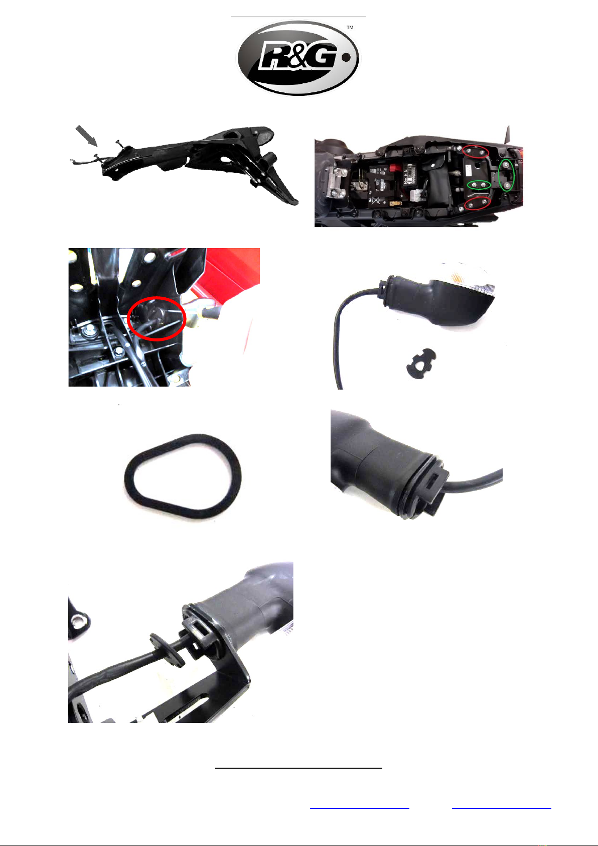
oLocate the indicators through the indicator mounting hole (using diluted washing up
liquid or similar) on the tail tidy assembly (placing the correct side indicator on the
correct side of the tail tidy, as previously marked on the wiring), and re-fit the small
plastic plate inside the rubber to securely mount the indicator, as shown in picture 23.
•Push the rubber bung (Item 3)through the centre hole of the cover plate (Item 2). (Picture
10)
•Once the wires of the number plate light have been wrapped with heat shrink, pass them
through the centre hole of both the number plate bracket (Item 1) & the cover plate (Item 2)
•Then push the threaded studs through the two adjacent holes and fit one of the small washers
included with the number plate light. (Picture 9)
•Place one of the small nuts into a 5.5mm ¼” drive socket then place over the stud with the
washer fitted. A micro ratchet will make this process easier but a ¼” drive with an extension
bar fitted can also be used.
•Turn the assembly so that the studs are vertical this will cause the nut to fall onto the stud
while remaining inside the socket. (Picture 11)
•Turn clockwise until the nyloc engages, then repeat on the other nut. (Picture 12)
•Once both washers and nuts are partially threaded onto the studs, tighten until the nut bottoms
out onto the cover plate (Do Not Overtighten).
•Push the number plate light shroud onto the light.
Disassembly Of The Standard Tail Unit
•Firstly, remove the seat from the motorcycle by turning the key in the hole in the undertray.
•Using an allen key remove the four bolts circled green in Picture 18, followed by the bolts
circled in red.
•Once removed, the seat lock bracket can be removed or moved aside allowing access to the
OEM lighting connectors & tail unit fixture bolts.
•Using a small flat head screwdriver, carefully un-plug the OEM lighting connectors attached to
the tail unit.
•Then remove the four bolts holding the OEM tail unit in place, circled green. (Picture 18)
•Once removed the tail unit will drop away form the bike and can be stored.
Fitting The
R&G
Tail Tidy
•Please follow the exploded view on page 3.
•Push the bolts (ITEM 5) through the washers or countersunk spacers (ITEM 6 Dependant on
which kit has been supplied) then through both the number plate bracket & cover plate.
(Picture 13 & 14)
•Once through, add the spacers (Item 8) onto the bolts. The assembly should now look similar
to Picture 15.
•Push the cables of the indicators & number plate light through the undertray so they can be
connected later.
•Pass the threaded portion of the bolts through the holes in the motorcycles undertray, holding
your hand flat against the heads of the bolts to keep the assembly in position.
Note: To make this process easier, you may use tape or blu tack (or similar) to hold
the bolts in place, then remove once the nuts have been partially threaded.
•Once through, apply the nyloc nuts to the end of each bolt and tighten until secure.
•Once secure, switch on the motorcycle’s ignition and test the indicator & licence plate light
function.
•Pull the tail unit cables through into the undertray as much as possible then using the cable ties
(Item 10) and self-adhesive clips (Item 12) see Picture 4, attach the cables to the inside of
the tail bracket to keep them out of sight.
Note: Please clean the surface you will be applying the self-adhesive clips to with
alcohol/solvent.
•Re-fit the OEM seat lock bracket (Picture 18)

Page 9of 29 LP0310BK
R&G Racing
Unit 1, Shelley’s Lane, East Worldham, Alton, Hampshire, GU34 3AQ
Tel: +44 (0)1420 89007 Fax: +44 (0)1420 87301 www.rg-racing.com Email: info@rg-racing.com
•Remove the number plate from the OEM tail unit then re-attach to the
R&G
tail tidy.
•Depending on local laws, a reflector may be required at the rear of the motorcycle. In this case,
please apply the included reflector (Item 17) to the number plate (Do not obscure the
characters).
IMPORTANT:
IF FITTING A FULL-SIZE LICENCE PLATE AND PLACING IT FAR DOWN ON THE LICENCE PLATE HANGER,
THERE IS A SMALL CHANCE OF THE LICENCE PLATE HITTING THE BACK WHEEL UNDER HEAVY LOAD AND
OVER LARGE BUMPS IN THE ROAD. IT IS YOUR RESPONSIBILITY TO CHECK FOR THIS POSSIBILITY AND TAKE
AVOIDING ACTION. FAILURE TO CHECK THIS COULD RESULT IN SERIOUS INJURY.
ISSUE 4 - 03/08/2021 (TB)
CONSUMER NOTICE
The catalogue description and any exhibition of samples are only broad indications of the Products and R&G may
make design changes which do not diminish their performance or visual appeal and supplying them in such state
shall conform to the order. The Buyer acknowledges no representation or warranty (other than as to title) has
been given or will apply to the Products other than those in R&G’s order or confirmation and the Buyer confirms it
has chosen the Products as being of merchantable quality and suitable for its particular purposes. Where R&G fits
the Products or undertakes other services it shall exercise reasonable skill and care and rectify any fault free of
charge unless the workmanship has been disturbed. The Buyer is responsible for ensuring that the warranty on
the motorcycle is not affected by the fitting of the Products. On return of any defective Products R&G shall at its
option either supply a replacement or refund the purchase money but shall not be liable if the Products have been
modified or used or maintained otherwise than in accordance with R&G’s or manufacturer’s instructions and good
engineering practice or if the defect arises from accident or neglect. Other than identified above and subject to
R&G not limiting its liability for causing death and personal injury, it shall not be liable for indirect or consequential
loss and otherwise its liability shall be limited to the amounts paid by the Buyer for the Products or the fitting or
service concerned. These terms do not affect the Buyer’s statutory rights.
R&G RACING RETURNS POLICY (NON-FAULTY GOODS)
Returns must be pre-authorised (if not pre-authorised the return will be rejected). Goods may only be returned
direct to us if they were purchased direct from us (customer must prove if necessary). Otherwise to be returned
to original vendor. Goods must be in re-sellable condition, in the opinion of R&G Racing. All returns are subject to
a 25% restocking and handling fee (25% of the gross value exc. P&P – at the prevailing price at time of
purchase). The customer must pay any and all carriage charges. No returns of discontinued products, unless
within 14 days of purchase. This policy does not affect your statutory rights and does not refer to faulty goods.

Page 10 of 29 LP0310BK
R&G Racing
Unit 1, Shelley’s Lane, East Worldham, Alton, Hampshire, GU34 3AQ
Tel: +44 (0)1420 89007 Fax: +44 (0)1420 87301 www.rg-racing.com Email: info@rg-racing.com
NOTICE DE MONTAGE POUR LP0310BK
SUPPORT DE PLAQUE
YAMAHA MT-09 STANDARD & SP 2021-
CE KIT CONTIENT LES ARTICLES ILLUSTRES ET ETIQUETES SUR LA PAGE.
CERTAINES PARTIES PEUVENT ETRE PRESENTES UNIQUEMENT POUR LA CLARTE DES INSTRUCTIONS.
NE PAS PROCEDER AU MONTAGE TANT QUE VOUS N'ETES PAS SUR QUE TOUTES LES PIECES SOIENT
PRESENTES.
VEUILLEZ LIRE TOUTES LES INSTRUCTIONS AVANT DE CONTINUER.
EN CAS DE DOUTE LORS DU MONTAGE DE NOS PRODUITS, CONSULTEZ UN DE NOS
REVENDEURS OU FAITES APPEL A UN TECHNICIEN QUALIFIÉ.
VEUILLEZ NOTER QUE LA FAÇON DONT LE KIT EST EMBALLE NE REPRESENTE PAS NECESSAIREMENT LA
MANIERE DE LE MONTER SUR LA MOTO.
SI DES RONDELLES EN CAOUTCHOUC SONT UTILISEES POUR MAINTENIR LES COMPOSANTS SUR LES
BOULONS,ELLES PEUVENT ETRE JETEES.
NOTICE DISPONIBLE AU TELECHARGEMENT SUR :
WWW.RG-RACING.COM

Page 11 of 29 LP0310BK
R&G Racing
Unit 1, Shelley’s Lane, East Worldham, Alton, Hampshire, GU34 3AQ
Tel: +44 (0)1420 89007 Fax: +44 (0)1420 87301 www.rg-racing.com Email: info@rg-racing.com
OUTILS REQUIS
•PISTOLET À CHALEUR
•PINCES
•CLÉS ALLEN
•TOURNEVIS PLAT
VALEURS DE SERRAGE
M4 BOULON = 8Nm
M5 BOULON = 12Nm
M6 BOULON = 15Nm
M8 BOULON = 20Nm
M10 BOULON = 40Nm
M12 BOULON = 40Nm
LÉGENDE
ARTICLE NO.
DESCRIPTION
QTÉ
ARTICLE 1
TB0310 PARTIE 1 SUPPORT DE PLAQUE
1
ARTICLE 2
TB0310 PARTIE 2 (COUVERCLE)
1
ARTICLE 3
RB0004 BOUCHON EN CAOUTCHOUC
1
ARTICLE 4
LA0002 FEU DE PLAQUE (LINCEUL)
1
ARTICLE 5
M6x1.00x30mm BOULONS
OU
M6x1.00x35mm BOULONS (PHOTOS 11 & 12)
4
ARTICLE 6
M6x19mmØ RONDELLES
OR
M6X22mmØ BOULONS (PHOTO 11 & 12)
4
ARTICLE 7
M6x1.00mm ÉCROUS
4
ARTICLE 8
S0384 M6x6.00mm ENTRETOISES
4
ARTICLE 9
666-896 180mm LONGUEUR DE MANCHON THERMO
RÉTRACTABLE 1
ARTICLE 10
CT220 205mm COLLIERS DE SERRAGE
2
ARTICLE 11
IWC0002 CACHES FILS DE MINI CLIGNOTANTS
2
ARTICLE 12
CLIP1 CLIPS CÂBLE AUTOCOLLANTS
4
ARTICLE 13
I0016 ADAPTATEURS DE CLIGNOTANTS
4
ARTICLE 14
I0037 ADAPTATEURS DE CLIGNOTANTS D’ORIGINE
2
ARTICLE 15
CON0034 CONNECTEURS DE CLIGNOTANTS
D’ORIGINE 2
ARTICLE 16
CON004 CONNECTEUR DE FEU DE PLAQUE
1

Page 12 of 29 LP0310BK
R&G Racing
Unit 1, Shelley’s Lane, East Worldham, Alton, Hampshire, GU34 3AQ
Tel: +44 (0)1420 89007 Fax: +44 (0)1420 87301 www.rg-racing.com Email: info@rg-racing.com
ARTICLE 17
REFL3 REFLECTEUR
1
ARTICLE 18
RGS0001 GROS STICKERS
2
ARTICLE 19
RGS0005 STICKERS EN CAOUTCHOUC
2
ARTICLE 20
QR CODE NOTICE DE MONTAGE
1
VUE D’ENSEMBLE
HOTOS DE MONTAGE
Photo 1
Photo 2

Page 16 of 29 LP0310BK
R&G Racing
Unit 1, Shelley’s Lane, East Worldham, Alton, Hampshire, GU34 3AQ
Tel: +44 (0)1420 89007 Fax: +44 (0)1420 87301 www.rg-racing.com Email: info@rg-racing.com
Préparer l’ensemble
•Veuillez suivre la vue d’ensemble ci-dessus.
•Tout d'abord, préparez le câblage de l'éclairage de la plaque d'immatriculation (article 4) et des
clignotants (si des micro clignotants de rechange sont installés à la place de ceux d’origine).
•Coupez deux petites sections de thermorétractable d'environ 10 à 15 mm de longueur pour une
utilisation ultérieure.
•Poussez les fils à travers le thermorétractable fourni et chauffez jusqu'à ce qu'il ne puisse plus
être déplacé librement (Photo 1).
Si vous Montez des micro clignotants
Comme le montre la photo 2, faites passer les fils à travers les adaptateurs de clignotant
(Article 13) suivis d'un écrou à bride (Article 7), puis le couvercle du câblage de
clignotant (Article 11).
oPasser l'un des adaptateurs de clignotant à travers le support de clignotant puis prendre
en sandwich les adaptateurs autour du support, pousser la partie filetée du clignotant à
travers l'assemblage et visser l'écrou sur le clignotant jusqu'à ce qu'il soit bien serré
(Photo 3).
Note: ne serrez pas complètement avant d'être assemblé sur la moto pour permettre le
réglage de l'angle.
oUne fois serré, poussez sur le couvercle du câblage de clignotant (Article 11) suivi d'une
petite section (10-15mm) de thermorétractable (Photo 5).
oUne fois le couvercle de câblage (Article 11) en place, placez la petite section de
thermorétractable sur la plus petite extrémité du couvercle de câblage puis appliquez de
la chaleur pour fixer en place (Photo 6).
oConnectez l'article 15 aux connecteurs sur les micro clignotants, puis fixez l'autre
extrémité au connecteur attaché au faisceau de câblage de la moto. (Photo 7)
oRépétez l'opération pour l'autre clignotant.
Si vous utilisez le feu de plaque R&G (Veuillez noter que pendant ce processus, le
connecteur de feu arrière d’origine devra être coupé pour conserver les connecteurs d'origine.)
oSi vous utilisez le feu arrière R&G, les connecteurs d’origine devront être retirés pour
créer des adaptateurs de connecteur de feu arrière similaires à l'image ci-dessous :
oCoupez le connecteur du feu arrière de celui d’origine en laissant suffisamment de fil
pour attacher les connecteurs FEMELLE CON0004 (article 16).
oÀ l'aide de pinces à dénuder, dénudez 10 mm de fil extérieur pour découvrir l'intérieur
en cuivre.
oGlissez l'un des couvercles en plastique inclus avec les CON0004 sur le fil comme illustré.
oFixez le connecteur FEMELLE au fil en sertissant le fil en position et en pliant les
languettes de fixation pour saisir le boîtier du fil comme indiqué dans le schéma ci-
dessus.
oFaites glisser l'extérieur en plastique sur le connecteur femelle, cela aidera à protéger la
connexion de l'eau.
Prenez une longueur de thermorétractable (article 9) et placez-la sur chaque paire de fils
de clignotants et chauffez soigneusement jusqu'à ce que les fils soient soigneusement
enveloppés, laissant les connecteurs exposés.
.
o.

Page 17 of 29 LP0310BK
R&G Racing
Unit 1, Shelley’s Lane, East Worldham, Alton, Hampshire, GU34 3AQ
Tel: +44 (0)1420 89007 Fax: +44 (0)1420 87301 www.rg-racing.com Email: info@rg-racing.com
Si vous montez les clignotants d’origine.
oLes clignotants d’origine doivent d'abord être retirés du support de plaque
d'immatriculation d’origine en démontant davantage le support de plaque.
oRetirez ensuite la plaque à l'intérieur de clignotant d’origine. (Photos 19 et 20)
oUne fois retiré, le clignotant peut être tiré à travers le trou de montage.
oPrenez les plaques d'adaptation de clignotant d’origine (article 14) et installez-en une sur
chaque caoutchouc de clignotant, comme indiqué sur les photos 21 et 22.
oLocalisez les clignotants à travers le trou de montage de clignotant (en utilisant du
liquide vaisselle dilué ou similaire) sur l'ensemble du support arrière (en plaçant le
clignotant latéral correct sur le bon côté du support arrière, comme indiqué
précédemment sur le câblage), et réinstallez le petite plaque en plastique à l'intérieur du
caoutchouc pour fixer solidement le clignotant, comme indiqué sur la photo 23.
•Pousser le bouchon en caoutchouc (Article 3) à travers le trou central de la plaque de
recouvrement (Article 2) (Photo 10).
•Une fois que les fils de l'éclairage de plaque d'immatriculation ont été enveloppés de film
thermorétractable, faites-les passer par le trou central du support de plaque d'immatriculation
(article 1) et de la plaque de recouvrement (article 2).
•Ensuite, poussez les goujons filetés dans les deux trous adjacents et placez l'une des petites
rondelles fournies avec l'éclairage de plaque d'immatriculation (Photo 9).
•Placez l'un des petits écrous dans un quart de tour à 5,5 mm, puis placez-le sur le goujon avec
la rondelle installée. Un micro cliquet facilitera ce processus, mais un quart de tour avec une
barre d'extension peut également être utilisé.
•Tournez l'ensemble de façon à ce que les goujons soient verticaux, cela fera tomber l'écrou sur
le goujon tout en restant à l'intérieur de la douille. (Photo 11).
•Tournez dans le sens des aiguilles d'une montre jusqu'à ce que le nyloc s'enclenche, puis
répétez l'opération sur l'autre écrou. (Photo 12)
•Une fois que les rondelles et les écrous sont partiellement vissés sur les goujons, serrez jusqu'à
ce que l'écrou touche le fond de la plaque de recouvrement (Ne pas trop serrer).
•Pousser la protection de l'éclairage de plaque d'immatriculation sur l'éclairage.
•Connectez l'article 16 à l'éclairage de la plaque d'immatriculation via les cosses rondes, puis
connectez l'autre extrémité au connecteur fixé au faisceau de câbles de la moto (Photo 8).
Démontage de l'unité de support de plaque standard
•Tout d'abord, retirez la selle de la moto en tournant la clé dans le trou du passage de roue.
•À l'aide d'une clé Allen, retirez les quatre boulons entourés de vert sur la photo 18suivis des
boulons entourés de rouge.
•Une fois retiré, le support de verrouillage du siège peut être retiré ou déplacé de côté pour
permettre l'accès aux connecteurs d'éclairage d’origine et aux boulons de fixation de l'unité
arrière.
•À l'aide d'un petit tournevis à tête plate, débranchez soigneusement les connecteurs d'éclairage
d’origine attachés à l'unité arrière.
•Retirez ensuite les quatre boulons qui maintiennent le support d’origine en place (Photo 18).
•Une fois retiré, le support se détachera de la moto et pourra être rangé.
Montage du support de plaque
R&G
•Veuillez suivre la vue d’ensemble à la page 3.
•Poussez les boulons (ARTICLE 5) à travers les rondelles ou les entretoises fraisées (ARTICLE 6
Selon le kit fourni) puis à travers le support de plaque d'immatriculation et la plaque de
recouvrement. (Photo 13 & 14).

Page 18 of 29 LP0310BK
R&G Racing
Unit 1, Shelley’s Lane, East Worldham, Alton, Hampshire, GU34 3AQ
Tel: +44 (0)1420 89007 Fax: +44 (0)1420 87301 www.rg-racing.com Email: info@rg-racing.com
•Une fois passé, ajouter les entretoises (Article 8) sur les boulons. L'assemblage devrait
maintenant ressembler à la photo 15.
•Faites passer les câbles des clignotants et du feu de plaque d'immatriculation à travers le
passage de roue afin qu'ils puissent être connectés ultérieurement.
•Passez la partie filetée des boulons à travers les trous du passage de roue de la moto, en tenant
votre main à plat contre les têtes des boulons pour maintenir l'assemblage en position.
Note: Pour faciliter ce processus, vous pouvez utiliser du ruban adhésif (ou similaire) pour fixer
les boulons en place, puis les retirer une fois que les écrous ont été partiellement filetés.
•Une fois à travers, appliquez les écrous nyloc à l'extrémité de chaque boulon et serrez jusqu'à
ce qu'ils soient bien fixés.
•Une fois fixé, mettez le contact de la moto et testez le fonctionnement des clignotants et du feu
de plaque d'immatriculation.
•Tirez les câbles du support autant que possible dans le passage de roue puis à l'aide des serre-
câbles (Article 10) et des clips autocollants (Article 12) voir Photo 4, fixez les câbles à l'intérieur
du support de plaque pour les empêcher de sortir.
Note: veuillez nettoyer la surface sur laquelle vous appliquerez les clips autocollants avec de
l'alcool/un solvant.
•Remontez le support de verrouillage de siège d'origine (Photo 18)
•Retirez la plaque d'immatriculation du support d’origine, puis rattachez-la au support de plaque
R&G.
•Selon les lois locales, un réflecteur peut être requis à l'arrière de la moto. Dans ce cas, veuillez
appliquer le réflecteur inclus (Article 17) sur la plaque d'immatriculation (Ne pas masquer les
numéros).
IMPORTANT:
SI VOUS INSTALLEZ UNE PLAQUE D'IMMATRICULATION DE GRANDE TAILLE ET LA PLACEZ
LOIN VERS LE BAS SUR LE SUPPORT DE PLAQUE D'IMMATRICULATION, IL Y A UNE FAIBLE
CHANCE QUE LA PLAQUE D'IMMATRICULATION FRAPPE LA ROUE ARRIÈRE SOUS L’EFFET
D’UNE CHARGE LOURDE ET SUR DE GRANDES BOSSES SUR LA ROUTE. IL EST DE VOTRE
RESPONSABILITÉ DE VÉRIFIER CETTE POSSIBILITÉ ET DE PRENDRE DES MESURES POUR
L'ÉVITER. NE PAS VÉRIFIER CECI POURRAIT ENTRAÎNER DES BLESSURES GRAVES.
ISSUE 4 - 03/08/2021 (TB)
CONSUMER NOTICE
The catalogue description and any exhibition of samples are only broad indications of the Products and R&G may
make design changes which do not diminish their performance or visual appeal and supplying them in such state
shall conform to the order. The Buyer acknowledges no representation or warranty (other than as to title) has
been given or will apply to the Products other than those in R&G’s order or confirmation and the Buyer confirms it
has chosen the Products as being of merchantable quality and suitable for its particular purposes. Where R&G fits
the Products or undertakes other services it shall exercise reasonable skill and care and rectify any fault free of
charge unless the workmanship has been disturbed. The Buyer is responsible for ensuring that the warranty on
the motorcycle is not affected by the fitting of the Products. On return of any defective Products R&G shall at its
option either supply a replacement or refund the purchase money but shall not be liable if the Products have been
modified or used or maintained otherwise than in accordance with R&G’s or manufacturer’s instructions and good
engineering practice or if the defect arises from accident or neglect. Other than identified above and subject to
R&G not limiting its liability for causing death and personal injury, it shall not be liable for indirect or consequential
loss and otherwise its liability shall be limited to the amounts paid by the Buyer for the Products or the fitting or
service concerned. These terms do not affect the Buyer’s statutory rights.
R&G RACING RETURNS POLICY (NON-FAULTY GOODS)
Returns must be pre-authorised (if not pre-authorised the return will be rejected). Goods may only be returned
direct to us if they were purchased direct from us (customer must prove if necessary). Otherwise to be returned
to original vendor. Goods must be in re-sellable condition, in the opinion of R&G Racing. All returns are subject to
a 25% restocking and handling fee (25% of the gross value exc. P&P – at the prevailing price at time of

Page 19 of 29 LP0310BK
R&G Racing
Unit 1, Shelley’s Lane, East Worldham, Alton, Hampshire, GU34 3AQ
Tel: +44 (0)1420 89007 Fax: +44 (0)1420 87301 www.rg-racing.com Email: info@rg-racing.com
purchase). The customer must pay any and all carriage charges. No returns of discontinued products, unless
within 14 days of purchase. This policy does not affect your statutory rights and does not refer to faulty goods.

Page 20 of 29 LP0310BK
R&G Racing
Unit 1, Shelley’s Lane, East Worldham, Alton, Hampshire, GU34 3AQ
Tel: +44 (0)1420 89007 Fax: +44 (0)1420 87301 www.rg-racing.com Email: info@rg-racing.com
MONTAGEANLEITUNG FÜR LP0310BK
KENNZEICHENHALTER
YAMAHA MT-09 STANDARD & SP 2021-
ALLE KIT-TEILE SIND AUF DEN NACHFOLGENDEN SEITEN ABGEBILDET UND GEKENNZEICHNET.
DIE ABGEBILDETEN TEILE DIENEN LEDIGLICH ZUR ERKLÄRUNG.
ÜBERPRÜFEN SIE ZUERST,DASS ALLE TEILE VORHANDEN SIND.
LESEN SIE DIE MONTAGEANLEITUNG KOMPLETT DURCH,BEVOR SIE ANFANGEN.
WENN SIE BEI DER MONTAGE DIESES PRODUKTES UNSICHER SIND, BITTE EINEN
UNSERER HÄNDLER KONTAKTIEREN ODER DAS KIT VON EINEM QUALIFIZIERTEN
ZWEIRAD-MECHANIKER MONTIEREN LASSEN.
DIE VERPACKUNG DER TEILE STELLT NICHT DIE REIHENFOLGE DER MONTAGE DAR.
HINWEIS FÜR KITS MIT PLASTIKUNTERLEGSCHEIBEN AN DEN SCHRAUBEN –
DIESE PLASTIK-UNTERLEGSCHEIBEN WERDEN NICHT FÜR DEN EINBAU BENÖTIGT.
SOME PARTS MAY BE SHOWN FOR CLARITY OF INSTRUCTIONS ONLY.
EINE DIGITALE VERSION DIESER MONTAGEANLEITUNG KANN AUF
FOLGENDER SEITE HERUNTERGELADEN WERDEN:
WWW.RG-RACING.COM
Table of contents
Languages:
Other R&G Motorcycle Accessories manuals
Popular Motorcycle Accessories manuals by other brands

hepco & becker
hepco & becker 6617504 01 01 installation instructions

Gazzini
Gazzini 10040330 Instructions for use

Uclear
Uclear HBC220 SNOW user manual

hepco & becker
hepco & becker 630734 00 01 Mounting instructions

hepco & becker
hepco & becker 6503530 00 01 Mounting instructions

hepco & becker
hepco & becker 42139521 00 01 quick start guide