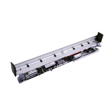
Record C 127 SU OFFSET User manual

record C 127 SU OFFSET
User manual
Your global partner for entrance solutions www.record.group

Document identification
Article nr.: 121-006454770
Version: 1.0
Publication date: 17/05/2022
Translation of the original manual
Subject to technical modifications
Copyright © agtatec ag

Table of contents
BAL_C127-SU_OFFSET_EN_1V0_REC_121-006454770 3 / 32
Table of contents
1 Safety................................................................................................................................................................. 5
1.1 Presentation of warning signs............................................................................................................... 5
1.2 Intended purpose of use ....................................................................................................................... 5
1.3 General hazards ................................................................................................................................... 6
1.4 State of technology ............................................................................................................................... 8
1.5 Personal protective equipment ............................................................................................................. 8
1.6 Spare parts and liability ........................................................................................................................ 9
2 General information ......................................................................................................................................... 10
2.1 Purpose and use of the instructions ..................................................................................................... 10
2.2 Copyright .............................................................................................................................................. 10
2.3 Product identification ............................................................................................................................ 10
2.4 Manufacturer agtatec ag....................................................................................................................... 10
2.5 Target groups ....................................................................................................................................... 10
2.6 Abbreviations ........................................................................................................................................ 10
3 Description........................................................................................................................................................ 12
3.1 Construction.......................................................................................................................................... 12
3.2 Versions................................................................................................................................................ 13
3.3 Components ......................................................................................................................................... 14
3.4 Functional description........................................................................................................................... 14
3.5 Accessories .......................................................................................................................................... 15
3.5.1 Lever arm......................................................................................................................................... 15
3.5.2 Gearbox cover with position switch.................................................................................................. 15
3.5.3 Extended function module FEM 1.................................................................................................... 16
3.5.4 Wind load brake ............................................................................................................................... 16
4 Technical Data .................................................................................................................................................. 17
4.1 Door leaf weights and door widths........................................................................................................ 17
4.2 Operator in stainless steel casing......................................................................................................... 18
5 Operation........................................................................................................................................................... 19
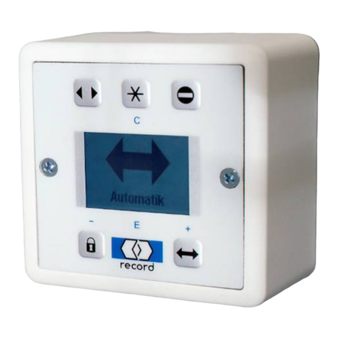
5.1 Control panel BDE-D ............................................................................................................................ 19
5.1.1 Operation modes and button functions ............................................................................................ 19
5.1.2 Perform reset ................................................................................................................................... 20
5.1.3 Display system information .............................................................................................................. 21
5.2 Parameter overview.............................................................................................................................. 21
5.3 Configuration C 127 STG 127 V3_00_E............................................................................................... 22
5.4 Configuration FEM V1_10 with STG127 V2_40_E............................................................................... 23
5.5 Description of parameters..................................................................................................................... 24
6 Servicing and maintenance ............................................................................................................................. 25
6.1 General remarks ................................................................................................................................... 25
6.2 Door care .............................................................................................................................................. 25
6.3 Logbook ................................................................................................................................................ 26
6.3.1 General information ......................................................................................................................... 26
6.3.2 Operator duties ................................................................................................................................ 27
6.3.3 Commissioned technician ................................................................................................................ 27
6.3.4 Legal principle.................................................................................................................................. 27
6.3.5 Extent of the inspection.................................................................................................................... 28
6.3.6 Requirements for documentation..................................................................................................... 28
7 Malfunctions ..................................................................................................................................................... 29
7.1 Status displays...................................................................................................................................... 29
7.2 Troubleshooting .................................................................................................................................... 29

Table of contents
4 / 32 BAL_C127-SU_OFFSET_EN_1V0_REC_121-006454770
8 Taking out of service and disposal................................................................................................................. 31
8.1 Decommissioning ................................................................................................................................. 31
8.2 Dismantling and disposal...................................................................................................................... 31

Safety 1
BAL_C127-SU_OFFSET_EN_1V0_REC_121-006454770 5 / 32
1 Safety
1.1 Presentation of warning signs
Various symbols are used in this guide for easier understanding:
NOTICE
Useful advice and information to ensure correct and efficient workflow of the system.
IMPORTANT
Specific details which are essential for trouble-free operation of the system.
IMPORTANT
Important details which must be read for proper function of the system.
CAUTION
Against a potential hazardous situation that can lead to minor personal injury and property
damage.
WARNING
Against a latent hazardous situation that can lead to severe injuries or death and cause sub-
stantial property damage.
DANGER
Against an imminent hazardous situation that can lead to severe injury or death.
DANGER
Against an imminent or latent hazardous situation that could lead to electric shock and cause
serious injury or death.
1.2 Intended purpose of use
The system is designed exclusively for use as a pedestrian passage. The installation must only occur
in dry areas. If there are deviations then proper waterproofing and water drains will be required on-
site.
Any other application or use beyond this purpose is not considered to be an intended purpose. The
manufacturer bears no liability for any resulting damage; the operator alone shall bear the associated
risk.
The intended purpose also includes observation of the operating conditions specified by the manufac-
turer, in addition to regular care, maintenance and repair.
Interventions in or alterations to the installation performed by non-authorized maintenance technicians
exclude the manufacturer's liability for consequential damages.

1Safety
6 / 32 BAL_C127-SU_OFFSET_EN_1V0_REC_121-006454770
1.3 General hazards
The following section lists hazards that can be caused by the system even when used as intended.
To reduce the risk of malfunction, damage to property or injury to persons and to avoid dangerous
situations, the safety instructions listed here must be observed.
The specific safety instructions in the other sections of this manual must also be observed.
IMPORTANT
The country-specific regulations must be observed and complied with!
IMPORTANT
To avoid malfunctions, moving objects such as flags or parts of plants must not be allowed to
enter the detection range of the sensors.
CAUTION
Risk of malfunctions, material damage or injury due to improper settings!
a) Improper settings can lead to malfunctions, material damage or personal injury.
ðDo not disconnect the system from the power supply overnight.
ðSettings should only be made by personnel qualified to do so.
ðDo not disassemble, put out of operation or manipulate safety devices.
ðHave faults rectified by specialist personnel or by personnel qualified to do so.
ðHave service and maintenance carried out according to locally applicable regulations or accord-
ing to a maintenance contract.
CAUTION
Risk of malfunctions, material damage or injuries due to insufficient or missing cleaning or
care!
a) Insufficient or inattentive cleaning or care of the system can lead to malfunctions, damage to
property or injury to persons.
ðCheck the sensors regularly for dirt and clean them if necessary.
ðRegularly remove dirt accumulations in the floor rail or under the floor mat.
ðKeep the system free from snow and ice.
ðDo not use aggressive or caustic cleaning agents.
ðUse road salt or loose chippings only conditionally.
ðLay the floor mat without folds and flush with the floor.
ðEquipment required for cleaning purposes such as ladders or similar must not be leaned on or at-
tached to the system.

Safety 1
BAL_C127-SU_OFFSET_EN_1V0_REC_121-006454770 7 / 32
CAUTION
Risk of material damage or injury due to unforeseen opening, closing or turning of the door!
a) The door can open, close or turn unexpectedly. This may result in damage to property or injury
to persons.
ðNo persons may be present in the opening area of the system.
ðEnsure that moving objects such as flags or parts of plants do not enter the detection range of
the sensors.
ðDo not make any settings on the control unit when the system is in use.
ðHave faults rectified immediately by specialist or personnel qualified to do so.
ðRemove objects from the opening area.
ðDo not disassemble, put out of operation or manipulate safety devices.
ðDo not rush through a closing system.
CAUTION
Risk of bruising and severing of limbs!
a) If the system moves, careless behaviour can lead to serious injuries to limbs or severance of
limbs.
ðDo not reach in when parts of the system are moving.
ðKeep a distance when parts of the system move.
ðDo not bump into or touch the system when it is moving.
ðDo not open or remove protective covers during operation.
ðDo not permanently remove covers from the system.
ðOnly carry out inspection, service, maintenance and cleaning when the system is stationary and
switched off.
CAUTION
Danger of material damage or injury due to non-functioning safety devices!
a) If safety devices are not functioning, manipulated or put out of operation, there is a risk of dam-
age to property or injuries that can lead to death.
ðNever disable or manipulate safety devices.
ðHave inspection, service and maintenance of the safety devices carried out according to local
regulations or according to a maintenance contract.
CAUTION
Danger of malfunctions, damage to property or risk of injury if used by unauthorised persons!
a) If unauthorised persons use the system, there is a risk of malfunction, damage to property or in-
jury to persons.
ðChildren under 8 years of age may only use the system under supervision.
ðChildren must not play, clean or maintain the system.
ðPersons with limited physical, sensory or mental abilities as well as persons with insufficient
knowledge or experience may only use the system under supervision or must have received and
understood instructions to do so.

1Safety
8 / 32 BAL_C127-SU_OFFSET_EN_1V0_REC_121-006454770
DANGER
Danger to life due to electric current!
a) In case of contact with live parts, there is an immediate danger to life due to electric shock.
Damage to or removal of the insulation or individual components can be life-threatening.
ðBefore starting work on active parts of electrical systems and equipment, ensure that all poles are
voltage free and that this is maintained for the duration of the work.
ðKeep moisture away from live parts. This can lead to a short circuit.
ðNever bridge fuses or put them out of operation.
ðDo not connect the power supply until all work has been completed.
ðHave work on the electrical system performed by qualified personnel only.
DANGER
Danger to life due to non-functioning safety devices of the fire protection system!
a) If safety devices of the fire protection system do not function properly, there is a risk of serious
or fatal injuries.
ðNever disconnect the fire protection system from the power supply overnight.
ðDo not disassemble, put out of operation or manipulate safety devices.
ðDo not remove safety instructions on the system.
ðNever block, hold open or otherwise prevent fire doors from closing.
ðHave inspection, service and maintenance of the fire protection system carried out in accordance
with locally applicable regulations or according to a maintenance contract.
ðHave the fire protection system checked and maintained according to the state of the art.
1.4 State of technology
This system was developed using state of the art technology and officially recognized technical safety
regulations. The system, depending on its options and diameter, comply with the requirements of the
Machine Guidelines 2006/42/EG as well as EN 16005 and DIN 18650 (D).
Nevertheless, danger may arise if not used as intended.
IMPORTANT
Installation, commissioning, inspection, maintenance and repair work may only be conducted
by qualified, trained and authorized technicians.
After commissioning or repair work, fill in the check list and give it to the customer for safe
keeping.
We recommend obtaining a service agreement.
1.5 Personal protective equipment
Personal protective equipment is used to protect persons from adverse effects on health. Personnel
must wear personal protective equipment during the various work activities on and with the system.
Personal protective equipment is explained below:
Hearing protection is used to protect the hearing from noise. As a rule of
thumb, hearing protection is compulsory from when normal conversa-
tion with other people is no longer possible.

Safety 1
BAL_C127-SU_OFFSET_EN_1V0_REC_121-006454770 9 / 32
The head protection serves to protect against falling and flying parts
and materials. It also protects the head from bumping into hard objects.
Protective goggles protect the eyes from flying parts, dust, splinters or
splashes.
Protective gloves are designed to protect hands from friction, abrasions,
punctures or serious injury and from burning caused by contacting hot
surfaces.
Safety shoes protect the feet from crushing, falling parts and slipping on
surfaces. The puncture resistance of the shoes ensures, that pointy ob-
jects do not penetrate the foot.
The high-visibility vest is used to make the personnel stand out and
therefore to be seen. With improved visibility and attention, the high-vis-
ibility vest protects personnel in busy work areas from collisions with
vehicles.
Depending on the place of work and the working environment, the protective equipment varies and
must be adapted accordingly. In addition to protective equipment for specific work, the work site may
require other protective equipment ( for example a harness).
In hygiene-protected areas, special or additional requirements of personal protective equipment may
be required. These requirements must be considered when choosing personal protective equipment.
If there is any uncertainty regarding the choice of personal protective equipment, the safety officer
must be consulted at the place of work.
1.6 Spare parts and liability
Reliable and trouble free operation of the door is only guaranteed when using parts that were recom-
mended by the manufacturer. The manufacturer declines any liability for damages resulting from un-
authorized modifications to the door or the use of parts that are not permitted.

2General information
10 / 32 BAL_C127-SU_OFFSET_EN_1V0_REC_121-006454770
2 General information
2.1 Purpose and use of the instructions
These instructions are an integral part of the system and enable efficient and safe handling of the sys-
tem. In order to ensure proper functioning, the instructions must be accessible at all times and kept in
the immediate area of the system.
Although only the male form has been chosen for reasons of better legibility, the information refers to
members of both sexes.
The operator must have read and understood the manual before starting any work. The basic require-
ment for safe working is to follow the safety instructions and the handling instructions. In addition, the
local regulations and safety rules apply.
The manual can be handed over in extracts to instructed personnel who are familiar with the opera-
tion of the system.
The illustrations are for basic understanding and may differ from the actual presentation. Specific rep-
resentations are contained in the drawings.
2.2 Copyright
The copyright for these instructions remains with:
agtatec ag
The instructions may not be reproduced, distributed, or used for the purpose of competition without
the written consent of agtatec ag.
Infringements shall result in the obligation to pay damages.
2.3 Product identification
The nameplate located on the door provides accurate identification of the product.
2.4 Manufacturer agtatec ag
agtatec ag
Allmendstrasse 24
CH – 8320 Fehraltorf
Switzerland
Phone: +41 44 954 91 91
Fax: +41 44 954 92 00
2.5 Target groups
CAUTION
Risk of injury if personnel are insufficiently qualified!
If unqualified personnel work on the system or are in the danger zone of the system, dangers may
arise which can cause serious injuries and considerable damage to property.
a) All work must be carried out by qualified personnel only.
b) Keep unqualified personnel away from danger areas.
This operating manual is intended for the target groups listed below:
– Operating entity of the system:
the person who is responsible for the technical maintenance of this system
– Operator of the system:
the person who operates the system every day and has been suitably instructed
2.6 Abbreviations
Abbreviation Description
ABS Absolute pulse generator
AKA Actuating-contact „outside“
AKG Actuating-contact „common“

General information 2
BAL_C127-SU_OFFSET_EN_1V0_REC_121-006454770 11 / 32
Abbreviation Description
AKI Actuating-contact „inside“
ASK Terminals inside header
ATE Drive unit
BDE-D Electronic control unit
BDI Control unit (rocker switch)
BDI-M Circuit board for mechanical control unit
BKL Control unit LED
BODYG Sensor „Bodyguard“
CAN-H Serial data interface
CAN-L Serial data interface
CPU Central processing unit
DFA Automatic swing door operator
EEPROM Program memory
ES Electrical circuit diagram
FV Manufacturing regulation
GTR Gearing
HS Main switch 2-pole
IKG Encoder
KA Cable exit
LED Light Emitting Diode
LD Light Emitting Diode
LS Cable plan
MF Multifunctional switch
MOT Motor
MP Principal assembly diagram
NA Emergency stop
NET Power supply unit
NS Main power switch
NSA Mains failure
RAD Radar, Motion sensor
RAILB Light barrier „Railbeam“
SI Fuse
SIO Safety open
SIS Safety close
SSK Key operated contact
STG Control unit
STP Control pc board
SURV Time switch „Locked“
TOE Door locking
TOW Door opening width
TOZ Door open time delay
µP Mikroprocessor
VAK Locking contact
VL Wiring list
VMA Instructions for wiring and assembly
VRR Locking

3Description
12 / 32 BAL_C127-SU_OFFSET_EN_1V0_REC_121-006454770
3 Description
3.1 Construction
1 Standard linkage (customer-specific) 11 Closing spring (in drive housing)
2 Housing cover 12 Multi-function button on STG control unit
3 Seal 13 STG control unit
4 Wind load brake 14 STG connecting terminals
5 C 127 SU H drive incl. control unit 15 Motorprint MOT
6 Stainless steel housing 16 Rotation direction slide switch S1
7 Spring force adjustment bolt 17 ATE drive unit connections
8 Spring force setting sight glass 18 Mains supply terminals
9 Output shaft connection (both sides) 19 Fine-wire fuse
10 Drive unit ATG 20 Power supply unit NET

Description 3
BAL_C127-SU_OFFSET_EN_1V0_REC_121-006454770 13 / 32
3.2 Versions
121-127812679
C127_SU_H-B_US_CCW-1_Offset
121-127812680
C127_SU_H-B_CCW-1_Offset
121-127812682
C127_SU_H-B_US_CW-2_Offset
121-127812683
C127_SU_H-B_CW-2_Offset
121-127812684
C127_SU_H-B_US_CW-1_Offset
121-127812685
C127_SU_H-B_CW-1_Offset

3Description
14 / 32 BAL_C127-SU_OFFSET_EN_1V0_REC_121-006454770
121-127812686
C127_SU_H-B_US_CCW-2_Offset
121-127812687
C127_SU_H-B_CCW-2_Offset
3.3 Components
The swing door operator forms part of an electromechanical swing door system and comprises the
following main components:
Control unit: Intelligent, self-learning microprocessor-controlled control system
Drive unit: Low maintenance DC geared motor with electronic path measurement and in-
tegral thermostatic protective switch, gear box with adjustable spring tension
Power supply: Compact 230 V power supply with integral input filter
Control unit: With simple mechanical operating unit and/or optionally with comfortable, pro-
grammable electronic operating unit BDE-D
Lever System: Power transmission to the door leaf with standard lever pushing or sliding
lever pulling / pushing
Locking (optional): Possibility on site to connect an electrical door opener (24 VDC)
Sensors: Aesthetic release and self-monitoring safety devices with adjustable sensitivity
ensure optimal, smooth and safe operation of the door system
3.4 Functional description
The C127 SU is designed so that it functions like a normal door closer when de-energised. It can
therefore be easily opened by hand and is closed by the energy stored in the spring, damped by the
motor which acts as a generator.
If the drive is connected to the mains, the opening and closing movements are motor-supported.
The following functions are solely intended for the safety of the user:
Obstruction detection:
If the door hits an obstruction while opening, it stops immediately and records the position of the colli-
sion. The drive attempts to briefly reach the open position during the hold-open time. Once the hold-
open time elapses, the door closes and, during the next opening, the obstruction position is passed
over very carefully in slow mode. This prevents a second hard impact.
Reversing:
If the door hits an obstruction while closing, re-opening is immediately initiated.

Description 3
BAL_C127-SU_OFFSET_EN_1V0_REC_121-006454770 15 / 32
3.5 Accessories
3.5.1 Lever arm
– For direct connection and force transmission between the output shaft and door leaf.
– The lever arm can be installed in the door panel or bottom rail profile of the door leaf.
– A suitable counteracting bearing must be provided for the door leaf.
NOTICE
The lever arm is manufactured according to customer requirements.
3.5.2 Gearbox cover with position switch
Gearbox cover with position switch
MS gearbox cover with switch
(position switch)
Art. 102-127808257
The normal gearbox cover is replaced by the gearbox cover with position switch. The adjustable
switch clasp in the gearbox housing actuates the microswitch with floating contact.
Solutions with externally mounted microswitches and appropriate operation or magnetic contacts
need to be implemented by the customer onsite.
Information for installing and setting can be found in the attached instructions Retrofitting mi-
croswitches (Nr. 102-127109418).
CAUTION
Unforeseen adjustment of the switch clasp during operation
a) Incorrect information about the position of the door leaf
ðThe switch contact may not be used for safety applications.
NOTICE
The AUX1_OUT output can be programmed with the functions Closed or Locked:
Closed: Door is closed.
Locked: Door is closed and locked.
For parameter configuration please also see the chapter Parameter Descriptions!

3Description
16 / 32 BAL_C127-SU_OFFSET_EN_1V0_REC_121-006454770
3.5.3 Extended function module FEM 1
Nameplate, connections and controls FEM 1
Mounting kit FEM 1 with 1 m cable FEM 1 module
102-020809040 102-020809033
4 potential-free inputs
Principle: Terminal connections:
+24 V: 64/66/68/70
O V: 65/67/69/71
14 relay outputs
Principle: Closing function Opening function Terminal connections:
73/76/79/82
88/90/92/94/96/98/100
102/104/106
74/77/80/83
89/91/93/95/97/99/101
103/105/107
– Relay with two-way contact 24 V / 1A
– Function (opening/closing contact) with selectable jumper
3.5.4 Wind load brake
If the door system is disconnected from the power supply, this will reduce any possible adverse ef-
fects caused by wind load and manual slamming open/close of the door.
Wind load module
Set comprising cam wheel, micro-switch with cable and
mounting bracket.
Art. No. 121-127812369
IMPORTANT
The wind load brake only functions when the drive is de-energised.

Technical Data 4
BAL_C127-SU_OFFSET_EN_1V0_REC_121-006454770 17 / 32
4 Technical Data
Dimensions: 850 x 260 x 160 mm (stainless steel casing LxBxT)
Operating voltage: 230VAC, 50/60 Hz oder 115VAC, 50/60 Hz
Power consumption: Standby 13 W, rated power 67 W
Max. torque: 80 Nm
Mass moment of inertia of door leaf: 140 kgm2
Opening angle: Adjustable from 70° to 115°
Time delay: Adjustable from 0 to 60 seconds (40 steps)
Opening speed: Adjustable from 3 to 20 seconds (40 steps)
Closing speed: Adjustable from 5 to 20 seconds (40 steps)
Noise emission: < 45 dB
Protection class: IP67
Environmental conditions
Temperature range: -15° C to +50° C
Humidity range: Up to 85% relative humidity, non condensing
Wind load: On request
4.1 Door leaf weights and door widths
The curves are calculated using the following formula:
J=1/3 x m x b2
Standard lever: J max. 140 kgm2Key: J = Mass moment of inertia kgm2
m = Door leaf weight in kg
b = Door leaf width in m

4Technical Data
18 / 32 BAL_C127-SU_OFFSET_EN_1V0_REC_121-006454770
4.2 Operator in stainless steel casing

Operation 5
BAL_C127-SU_OFFSET_EN_1V0_REC_121-006454770 19 / 32
5 Operation
See also:
2Configuration C 127 STG 127 V3_00_E [}22]
2Configuration FEM V1_10 with STG127 V2_40_E [}23]
5.1 Control panel BDE-D
5.1.1 Operation modes and button functions
The buttons on the control panel BDE-D are used to set the door system operation modes in the main
menu. The parameters of the door system are set in the sub menu.
The button functions are divided into main menu and sub menu.
Main menu
Button Name Operation Function Display on LCD
Automatic button Press button 1 x Automatic operation via
sensors
Automatic
Continuously open
button
Press button 1 x For sliding door operator
and swing door operator:
continuously open, sensors
disabled
Continuously open
Press button 2 x or hold it
down for 2 seconds
For sliding door operator:
manual operation
Manual
One-way button Press button 1 x Passage only possible from
one direction
One-way
Locking button Press button 1 x Door closed, sensors dis-
abled
Locked
Press button again The door opens again,
closes, and locks again.
Can be opened with a key
(optional).
Locked
Star button Press button 1 x For sliding door operator:
Reduced open width
Automatic
Press button 1 x For swing door operator:
manual operation
Manual
E
Menu button Restart control device:
press button for 5 seconds
Restart hardware BDE-D:
press button for 12 seconds
Access to parameter menu
Enable control lock
Restart control device
Restart hardware BDE-D

5Operation
20 / 32 BAL_C127-SU_OFFSET_EN_1V0_REC_121-006454770
Sub menu
NOTICE
The main menu is returned to automatically 3 minutes after the last entry.
Button Name Operation Function Display on LCD
E
Enter button Press button 1 x to go to
the next sub menu.
Select menu item, confirm
entry
Opening speed
0 10 20 30 40
+
Plus button Press button 1 x to go
down.
Navigate downwards in the
menu
Parameter
Driving cycle
Time delay open
Operator
Press button 1 x to increase
the value.
Move the slide control to
the right to increase the
value
Closing speed
0 10 20 30 40
-
Minus button Press button 1 x to go up. Navigate upwards in the
menu
Parameter
Driving cycle
Time delay open
Operator
Press button 1 x to reduce
the value.
Move the slide control to
the left to reduce the value
Closing speed
0 10 20 30 40
C
Clear button Press button 1 x to go to
the previous menu.
Leave the menu item
without saving.
Parameter
Driving cycle
Time delay open
Operator
5.1.2 Perform reset
Reset controller
Step Button Operation Function Display on LCD
1.
E
Press button for 5 seconds Perform controller reset
No
Reset controller?
Yes
2.
C
Press button 1 x Cancel reset
E
Press button 1 x Perform reset
Table of contents
Other Record Door Opening System manuals

Record
Record DFA 127 User manual

Record
Record DFA 127 Setup guide

Record
Record 5100 Series User manual

Record
Record STA20 User manual

Record
Record C 127 SU H User manual

Record
Record S20 Series User manual

Record
Record FlipFlow TWIN User manual

Record
Record 5100 Series User manual

Record
Record STM 20 RED/DUO User manual

Record
Record BDE-D User manual

Record
Record K 32 M User manual

Record
Record system 20 RED Series User manual

Record
Record C 127 SU S User manual

Record
Record DFA 127 User manual

Record
Record R62 User manual

Record
Record C 127 X SU H-B OFFSET User manual

Record
Record K32 ST User manual

Record
Record HA8-SP Service manual

Record
Record system 20 Repair manual

Record
Record DFA 70 User manual