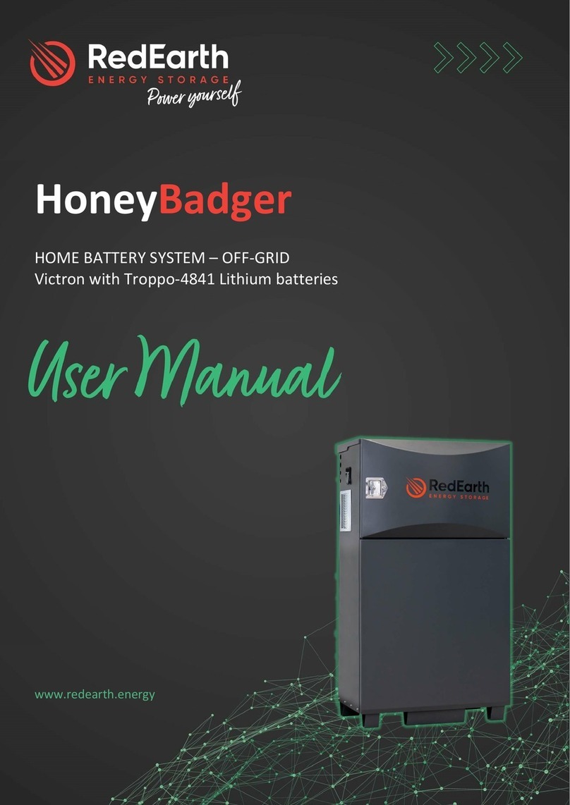
RedEarth BushChook User manual

Installation and Operation Manual
BushChook
• Whole home backup option
• On-grid and off-grid homes
• 1-phase and 3-phase homes
RedEarth’s BushChook systems offer
Australian-made scalability, making
them an excellent and enduring investment
for your home. Available in both single
and three-phase configurations, the
BushChook provides a range of power outputs
tailored to accommodate your specific needs
.

BushChook – Installation and Operation Manual
Page 2 of 48
Issue date: 19/12/2023. Version 1.1
Safety instructions
Symbol
Explanation
Indicates additional information, emphasized contents or tips that may be helpful.
Caution, risk of electric shock.
Caution, risk of danger.
Do not touch live parts until 10 minutes after disconnection from the power sources.
The wiring diagrams and installation instructions are given as a guide only and compliance to appropriate standards is
the responsibility of the installer. Relevant standards are listed below:
AS/NZS 3000:2018
Wiring rules
AS/NZS 5033:2021
Installation and safety requirements for photovoltaic (PV) arrays
AS/NZS 4509.2:2012
Stand
-alone power systems-Design
AS/NZS 1170.2:2021
Structural design actions
-Wind actions
AS/NZS1768:2021
Lightning protection
AS/NZS 3008.1.2:2017
Electrical installations
– Selection of cables
AS/NZS 5139:2019
Electrical installations
-Safety of battery systems for use with power conversion equipment
The BushChook must only be installed by suitably qualified personnel who have read and are familiar with its operation
and hazards.
The battery provided with this system must only be charged by the Deye inverter or the V2G (vehicle to grid) charger
supplied by RedEarth. Do not attempt to charge the batteries with any other charging device or connect any devices
directly to the DC battery bus unless approved by RedEarth.
In the event of a fire evacuate the area and call emergency services. A dry agent fire extinguisher should be readily
available and used. DO NOT use water. MSDS document is provided with the system and can be found at
www.redearth.energy
Do not use a damaged battery. Batteries should only be disposed of at an appropriate recycling centre. Please
contact RedEarth for advice.
A battery can present a risk of electrical shock and high short-circuit current. The following precautions should be
observed when working on batteries:
• Remove watches, rings, and other metal objects.
• Use tools with insulated handles.
Disconnect charging source prior to connecting or disconnecting battery terminals.
In our efforts towards constant product enhancement, this document is subject to change at any time. Please visit
www.redearth.energy and download the appropriate and latest version manual.
Lifting hazard
The BushChook is heavy. Observe proper lifting techniques. To reduce the weight the Troppo batteries can be removed.
Fire
The BushChook uses RedEarth's Troppo battery. This is a lithium-iron-phosphate based battery (LFP). It is the safest lithium
chemistry. However, in the case of a fire the following steps should be taken. A dry agent fire extinguisher should be readily
available and used. DO NOT use water. Evacuate the area and call emergency services. Tox i c g a s m a y be produced if the
battery catches fire.
Note:
The SDS document for the Troppo Battery can be found at www.redearth.energy
WARNING:
Working on the inside of the BushChook system is restricted to qualified
personnel. RedEarth recommend installation by licensed electricians only.

BushChook – Installation and Operation Manual
Page 3 of 48
Issue date: 19/12/2023. Version 1.1
Ta b l e o f C o n t e n t s
Overview..............................................................................................................................................................................................................................4
Dimensions and positioning information ...............................................................................................................................................................6
BushChook weight, size, and IP rating:.............................................................................................................................................................6
Positioning information summary:.......................................................................................................................................................................6
Overview of the installation tasks ............................................................................................................................................................................7
Internal Components Description..........................................................................................................................................................................10
Opening the BushChook......................................................................................................................................................................................10
Inside Layout .............................................................................................................................................................................................................10
Battery area ...............................................................................................................................................................................................................10
Inverter area...............................................................................................................................................................................................................11
Electrical panel area..............................................................................................................................................................................................11
Parts kit and documentation: .............................................................................................................................................................................12
Installation: 8 steps for installation and customer handover....................................................................................................................13
Step 1. Transporting.................................................................................................................................................................................13
Step 2. Positioning .....................................................................................................................................................................................14
Step 3. Solar installation..........................................................................................................................................................................15
3.1 PV String configuration ..................................................................................................................................................................15
3.2 PV Isolators.........................................................................................................................................................................................17
Step 4. Electrical connections..............................................................................................................................................................17
4.1 Grid, Load and Smart Port connection ...................................................................................................................................18
4.2 Main Switchboard wiring & Feed-in Meter Installation....................................................................................................20
4.3 Battery connection..........................................................................................................................................................................23
4.4 Earth Fault Alarm...............................................................................................................................................................................24
4.5 Solar connection ..............................................................................................................................................................................24
4.6 Connecting the BushChook in an Off-Grid Installation ...................................................................................................25
Step 5. Understanding the Turn ON/SHUTDOWN Procedure.................................................................................................26
Step 6: Commissioning the system....................................................................................................................................................27
6.1 Power up the BushChook system ............................................................................................................................................27
6.2 Access the inverter via the Solarman APP, using Local Mode. ...................................................................................27
6.3 Confirm the Inverter Initial configuration including regional settings .......................................................................28
6.4 BushChook Fault Codes................................................................................................................................................................32
6.5 Te s t t h e o p e r a t i o n o f t h e c o m p le t e s y s t e m p r i o r t o h a n d ov e r t o t h e c u s t o m e r . ................................................34
Step 7. Activating Remote Monitoring and Communications .................................................................................................34
Step 8: Customer Handover ..................................................................................................................................................................35
Services and options available for your BushChook....................................................................................................................................37
Te c h n i c a l s u p p o r t .........................................................................................................................................................................................................38
Appendix A.......................................................................................................................................................................................................................39
Single Line Diagram—Power (1-phase and 3-phase versions) ..........................................................................................................39
Single Line Diagram—Communications (1-phase and 3-phase are the same)...........................................................................41
Single Line Diagram—Main Switchboard (1-phase and 3-phase versions) ..................................................................................42
Appendix B.......................................................................................................................................................................................................................44
Te c h n i c a l S p e c i fi c a t i o n s - BushChook systems.......................................................................................................................................44
Troppo-4841 battery specifications...............................................................................................................................................................45
BushChook – Installation and Operation Manual
Page 4 of 48
Issue date: 19/12/2023. Version 1.1
Overview
RedEarth's BushChook home battery system is your complete solution for both on-grid and off-
grid homes. There are models for both single-phase (8kW & 5kW) and three-phase (12kW)
homes.
BushChook is an all-in-one battery system designed to be very easy to install. As an Australian-
made product built in Brisbane, RedEarth provides best-in-class support for BushChook owners
and installers.
The system, including solar panels, generates and stores electricity for use day & night, and
includes a whole-home backup capability so that customer’s loads remain powered during any
blackout (load dependent).
For the homeowner it minimises electricity bills, optimises electricity usage (including electric
vehicle charging) and reduces the homes carbon footprint.
RedEarth also provides the option of ongoing manufacturer support and benefits for 10 years
after the BushChook has been installed by joining RedEarth's
Optimum program.
RedEarth's Optimum program also provides access to
RedEarth’s PPP (Private Power Plant), to generate additional
income such as through Energy Trading or Smart EV
charging. Contact RedEarth for additional information.
The BushChook battery system is monitored and controlled
via RedEarth’s EMU app, available for both Apple and Android
phones.
Installation features:
• The BushChook system can easily be retrofitted to an existing PV solar system that may
already be installed at the home.
• Solar panels: Up to 18kW of panels can be connected to the 12kW 3-phase BushChook
and 12kW of panels to the 8kW 1-phase BushChook. This is usually enough to meet the
needs of a typical home as well as charge an electric vehicle using only electricity
generated at home.
• The BushChook is designed so that additional batteries can easily be added in the future,
right up to eight batteries with a total of 32.8kWh. Buy what is needed now, and add more
later as demand grows, e.g., an electric vehicle is purchased.
RedEarth’s Private Power Plant (PPP)
Transforming your home into a more valuable and lucrative investment is easily achievable
through the integration of RedEarth systems and proprietary Private Power Plant (PPP). As we
step into an electrified future, homes need to be ready. By harnessing the untapped potential of
your rooftop, you can generate up to three times the amount of solar energy needed to power
your residence or business. The result? Your property becomes your very own Private Power

BushChook – Installation and Operation Manual
Page 5 of 48
Issue date: 19/12/2023. Version 1.1
Plant, RedEarth’s ground-breaking innovation
that offers a myriad of advantages.
With RedEarth systems installed, you not
only gain access to a continuous source of
renewable energy but also create an
additional revenue stream by feeding surplus
energy back into the grid. This not only
offsets your energy costs but could even
turn a profit. Additionally, you contribute to a
sustainable future by significantly reducing
energy waste and, over time, effectively
eliminating power bills. The decision to
"RedEarth-ify" your home is not just an
investment in the present but a forward-
thinking step towards financial security, eco-
friendliness, and long-term value
enhancement for your property.
RedEarth offers its PPP to generate more value for BushChook battery system owners than is
generally available from other battery systems which do not offer an ongoing support program
like RedEarth's Optimum. Contact RedEarth for more details.
BushChook is fully certified to AS4777.2:2020 & IEC62109.1&2 & AS60950.1 and conforms to
the Australian Battery Safety Guide.

BushChook – Installation and Operation Manual
Page 6 of 48
Issue date: 19/12/2023. Version 1.1
Dimensions and
positioning information
BushChook weight, size, and IP
rating:
Positioning information summary:
• 465kg with 8 x TROPPO Lithium
batteries (42.5kg per battery)
• 125kg complete without batteries.
• 1040H x 1180W x 580D [mm]
Minimum clearance around BushChook where no
windows doors etc are allowed. According to
AS/NZS 5139.
Note:
if the system is >300mm off the
wall then this does not apply. The BushChook
system should be installed in a shaded area.
Single-Phase 5KW system
BC-5-1xx model numbers:
Single-Phase 8KW system
BC-8-1xx model numbers:
Three-Phase 12kW system
BC-12-3xx model numbers:
BC-5-108
(x2 battery = 8.2kWh nominal)
BC-8-112
(x3 battery = 12.3kWh nominal)
BC-12-316
(x4 battery = 16.4kWh nominal)
BC-5-112
(x3 battery = 12.3kWh nominal)
BC-8-116
(x4 battery = 16.4kWh nominal)
BC-12-320
(x5 battery = 20.5kWh nominal)
BC-5-116
(x4 battery = 16.4kWh nominal)
BC-8-120
(x5 battery = 20.5kWh nominal)
BC-12-324
(x6 battery = 24.6kWh nominal)
BC-5-120
(x5 battery = 20.5kWh nominal)
BC-8-124
(x6 battery = 24.6kWh nominal)
BC-12-328
(x7 battery = 28.7kWh nominal)
BC-5-120
(x5 battery = 20.5kWh nominal)
BC-8-128
(x7 battery = 28.7kWh nominal)
BC-12-332
(x8 battery = 32.8kWh nominal)
BC-5-124
(x6 battery = 24.6kWh nominal)
BC-8-132
(x8 battery = 32.8kWh nominal)
BC-5-128
x7 battery = 28.7kWh nominal)
BC-5-132
(x8 battery = 32.8kWh nominal)

BushChook – Installation and Operation Manual
Page 7 of 48
Issue date: 19/12/2023. Version 1.1
Overview of the installation tasks
A typical complete installation of the BushChook home battery will require the electrical
connection of the following items. If the home is only off-grid then there is no need to connect
the grid or the feed-in meter/CT, but a backup generator will very likely be required.
Note: Differences between 1-phase and 3-phase systems are highlighted where necessary.
1.
Grid:
AC cables run from the MSB (Main switchboard) directly to the grid terminals
inside the BushChook system. In 3-phase system observe the correct phase
rotation.
2.
Feed-in Meter/CT
(supplied) Required for on-grid systems that are not installed as
whole home backup. It is installed in the MSB and connected to the BushChook
system via a Cat5/6 cable or similar (not supplied).
The information from this meter
affects the operation of the BushChook system, make sure both the wires and CT
are connected the right way around.
o In addition to the Feed-in meter the MSB will also require a MCB to be installed
to allow the BushChook system to be isolated, for example to work on the MSB.
3.
Load:
AC cables from the MSB directly to the Load terminals inside the BushChook
system.
o
Note:
The BushChook system is designed as a whole home backup system,
however if the loads in a particular house are greater than the capacity of the
BushChook system then the loads inside the MSB will need to be split to ensure
that the backed-up circuits do not overload the BushChook system.
o The BushChook 3-ph is rated at 12kW and the 1-phase at either 8kW or 5kW,
depending on which system was ordered. Loads such as pool pumps and under
floor heating should probably not be backed up.
o Putting too many loads on the backed-up circuit can also empty the battery
quickly during an outage. In this case additional battery capacity may be
required. Note that the BushChook has a multi-purpose SMART Port that can act
as a Smart load which can be programmed to turn off at a pre-determined
battery state-of-charge (SOC) leaving the remainder of the battery capacity for
more critical loads. see details below under
Optional - SMART Port connection.
4.
Solar:
The BushChook has 2 MPPTs. The 5KW 1-phase BushChook accepts up to 2
arrays of PV solar panels, the 8KW 1-phase BushChook accepts up to 4 arrays,
where each tracker accepts two strings in parallel. The maximum string voltage on
the 1-phase systems is 500Vdc. The 3-phase BushChook accepts up to 3 arrays,
where two of these are paralleled into one of the MPPTs. The maximum string
voltage on the 3-phase systems is 800Vdc, although 600Vdc may be the maximum
voltage allowed on a residential installation.
5.
Batteries:
The BushChook is pre-wired for up to eight Troppo batteries. Each Troppo
battery has a nominal capacity of 4.1kWh. The batteries need to be installed and
plugged in.
6.
Remote monitoring:
The BushChook system needs to be connected to the internet
to provide its full capabilities. Note this applies to both on-grid and off-grid
Installations. If no Internet connection is available, then no remote monitoring is
available for the BushChook system. RedEarth provides 4G internet during the first
3-month trial of any BushChook installation. After the 3-month trial the customer can
choose to join RedEarth's Optimum Customer Support program, and the 4G internet
option will continue, otherwise the customer can provide their own internet if they
want remote monitoring.

BushChook – Installation and Operation Manual
Page 8 of 48
Issue date: 19/12/2023. Version 1.1
o A cell phone booster option is also possible in areas with poor mobile phone
coverage. Contact RedEarth for details.
o Hard-wired internet cable from the home internet router to the BushChook
system can be installed if available. This provides the most robust
communication link versus a Wi-Fi or 4G signal.
7.
Optional - SMART Port connection:
The BushChook system has a third AC
connection option, the SMART Port that can perform different functions depending
on how it is configured. It can connect an auto-start generator, but it can
alternatively be configured to either connect and manage a separate AC-coupled
PV inverter OR it can power a "smart load" such as a pool heater or crypto miner.
See notes below.
By Default, the SMART port is configured to operate a Backup
Generator, please notify RedEarth at the time of sale, or installation if you wish to
adjust this
.
o Smart Load: If connecting a smart load, run your designated smart circuit into the
ac breaker labelled Smart / Gen. This load will run when the batteries are above
a programmed state of charge, and power down when the batteries fall below
this SOC. For example, an air-conditioned could be powered via this SMART Port
so that in a power outage it will continue running until the battery reaches a pre-
programmed SOC. The SMART port can also be configured to always provide
power to this circuit when the grid Is connected, independent of the battery
SOC.
o AC Coupled Solar: An AC coupled solar Inverter or micro-inverter can be
connected into the terminal labelled
Smart / Gen terminal
. This opens up the
opportunity to redirect the output of an existing PV system to this port, allowing
it to be controlled by the BushChook system. Note: It is important that the
shutoff frequencies are set appropriately so that the BushChook system can
correctly manage this extra AC-coupled PV system (consult RedEarth tech
support), and it Is also essential that the AC coupled PV does not exceed a 1:1
relationship to the BushChook Inverter size (5kW or 8kW for 1-phase or 12KW
for 3-phase).
o Generator: The SMART port is set to generator in the default configuration of the
BushChook. This mode will automatically call your generator when the SOC
reaches a lower SOC (battery voltage setting), this will then stop the generator
when the SOC reaches the higher SOC (battery voltage setting), If you require
assistance adjusting these two set points contact RedEarth tech support. The
BushChook includes a 2-wire generator auto-start feature. See Section 4.6 for
details.

BushChook – Installation and Operation Manual
Page 9 of 48
Issue date: 19/12/2023. Version 1.1
Key additional tasks to complete the installation include;
1.
Book the install with RedEarth:
When you know the installation date, book the time
with RedEarth so that they are sure to be there to help you and also confirm that the
system and the remote monitoring is properly setup.
2.
Optional - receive training on the BushChook system at RedEarth's facility In
Brisbane.
It Is also possible for RedEarth to provide training at reseller/installer
facilities.
3.
Adjusting the programming of the BushChook inverter
for the customer’s specific
requirements. (e.g. adjust the level of grid-feed allowed by the utility or modifying
the SMART Port function). Use the
Solarman Smart APP
operating in local mode to
access these settings. See STEP 6 - Commissioning the System
4.
Handover to the customer:
this includes demonstrating what circuits are backed up
during an electricity outage (by actually turning off the grid supply) as well as
demonstrating how the backup generator works (if one is installed) and confirming
that it charges the battery system.
5.
Customer to scan the QR code:
This is important for the customer to be able to
monitor their system on RedEarth's EMU app as well as access the benefits of
RedEarth's Optimum and Private Power Plant features. It also registers the warranty.
Note:
The BushChook is not designed to act as the customers MSB as it does not
include space for additional main & customer circuit breakers or RCDs. RCD’s must be
installed in the MSB as required by AS4777.2:2020.

BushChook – Installation and Operation Manual
Page 10 of 48
Issue date: 19/12/2023. Version 1.1
Internal Components Description
Opening the BushChook
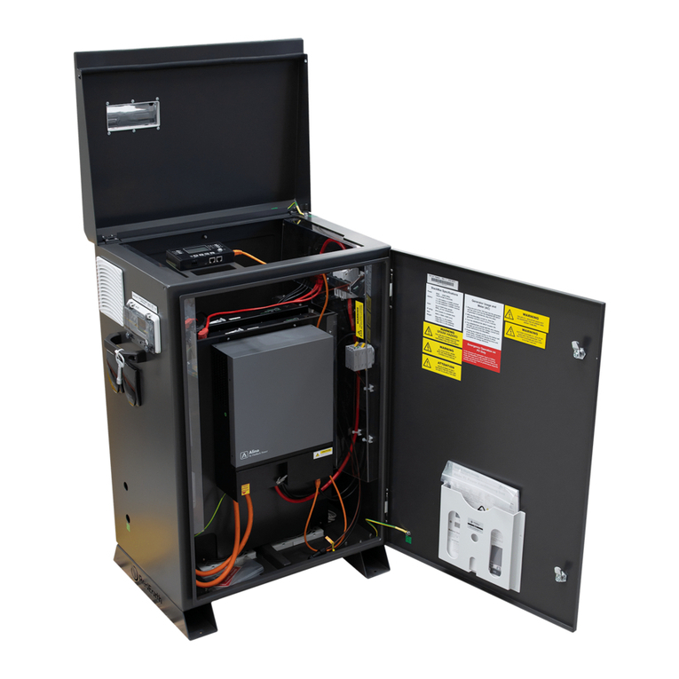
RedEarth’s BushChook Home battery system can
be accessed by removing the lid. To do this,
remove the nine (9) screws with a Philips
screwdriver (PH2), lift and pull the cover away from
the unit and place in a safe location.
Inside Layout
The BushChook is divided into three main areas. On the Lefthand side (LHS) are the batteries, in
the middle Is the Inverter and on the Righthand Side (RHS) are the electrical components and
cable connection points for installation. Prior to leaving the factory the system is tested. It
leaves the factory with the inverter cabling fully connected and ready-to-run. The batteries are
usually removed for transportation.
Battery area
Up to 8 x RedEarth Troppo-4841 Lithium batteries can be installed in
the BushChook.
All eight sets of battery cables are pre-wired into the system. This
makes it very easy to add additional batteries in the future.
Note that the battery modules are usually shipped separately and
installed during installation.
Removal of the cover must only
be done by qualified personnel.

BushChook – Installation and Operation Manual
Page 11 of 48
Issue date: 19/12/2023. Version 1.1
Inverter area
Here you will find the Deye Inverter (5KW, 8KW or 12KW). All the connections to it are already
made to the inverter and the fans are pre-wired, so there is no installation wiring to be done in
this area.
Electrical panel area
This area Is designed for easy access to all the switchgear and wiring, like a typical
switchboard.
To a c c e s s t h i s p a n e l t o r i g h t-side cover of the BushChook system is removed. Here you will find
all the protection devices and the connection points needed to wire in the system during
installation.
There are labels to clearly identify where cables are connected during installation.
Note that the wiring and switchgear for the three-phase and single-phase panels is different.

BushChook – Installation and Operation Manual
Page 12 of 48
Issue date: 19/12/2023. Version 1.1
Parts kit and documentation:
The BushChook is supplied with documentation and a parts kit box to complete the installation.
Documentation
o BushChook installation manual
o BushChook user manual
o BushChook identification sheet (serial #s etc)
o Feed-in meter manual (Eastron)
o Inverter manual – Deye
o MSDS – Troppo battery
Parts Kit Box:
o Documentation listed above.
o Feed-in meter (Eastron 1-ph or 3-ph version) `for installation in the switch board plus CTs
to connect to the meter (one for 1-ph and three for 3-ph). Note that a Cat5/6 cable or
similar to connect the feed-In meter back to the BushChook system Is NOT supplied
and needs to be provided by the installer.
o Stickers and Traffolytes required to complete the installation.
o 4 x Dynabolts for securing the BushChook system to the ground.
o 2x M16 Gland for the comms antenna
o 6x M25 glands (suitable for sealing around 25mm flexible conduit)
o Suitable circuit breakers for installation into the switchboard to isolate the BushChook
when required. (1-phase 1 x 40A or 50A 2-pole, 3-phase 2 x 40A 3-pole)

BushChook – Installation and Operation Manual
Page 13 of 48
Issue date: 19/12/2023. Version 1.1
Installation: 8 steps for installation
and customer handover
The BushChook system is designed to be easy to install. It includes prewired connection points
and comprehensive labelling and parts kit to simplify the installation.
Te c h n i c a l s u p p o r t i s a v a i l a b le d i r e c t l y f r o m R e d E a r t h d u r i n g i n s t a l l a t i o n i f r e q u i r e d . C o n t a c t
details are included at the back of this manual.
8 steps to complete your BushChook installation:
1. Transporting – getting the BushChook to site.
2. Positioning – the BushChook in its final location
3. Solar Installation – including bringing the PV cabling to the BushChook system.
4. Electrical connections – at the BushChook system and the house switch board
5. Understanding turn on/shutdown procedures.
6. Commissioning the system – turning on and programming and confirming system
operation
7. Activating remote Monitoring and Communications – contact RedEarth to confirm
remote operation.
8. Customer Handover – including scanning the QR code and their access to the EMU app.
Step 1. Transporting
The BushChook system is usually supplied on a
pallet, with the batteries in separate cardboard
boxes. It has been factory tested; however, the
batteries are usually subsequently removed for
transportation. Without batteries but with all other
components in place the 8kW 1-phase system
weighs 115kg and the 12kW 3-phase system
weighs 125kg.
The BushChook 8kW 1-phase system weighs 455kg
when filled with 8 lithium batteries. The BushChook
12kW 3-phase weighs 465kg when filled with 8 Troppo batteries.
The image shows a BushChook with batteries packed separately as well as a second pallet of
solar panels in a trailer.
WARNING: Personal Injury
Use safe lifting techniques and standard safety equipment
when transporting and installing the BushChook system.

BushChook – Installation and Operation Manual
Page 14 of 48
Issue date: 19/12/2023. Version 1.1
Step 2. Positioning
The BushChook is designed as a freestanding weatherproof system (IP43).
It should be installed in a shaded area to minimise the chance of overheating. If
the system overheats past 45degC the power output will start to derate until it
reaches 60degC at which point It will shut down. (Once the system cools down
again it will restart automatically).
The BushChook system should be located at least 100mm off the wall to allow
for proper ventilation through the rear vents. If possible, it should be placed
closer to the solar panels and the main switchboard to minimise cable run
length and voltage drop/power loss.
• If the system is installed within 300mm of a wall then, to comply with
Australian standards for a house, allow space around the system as shown
In the image at right (no doors or windows within the shaded area).
• Note: the material that the wall is made of (its flammability) can
influence the allowed positioning, however, if the BushChook
system is installed >300mm off the wall then the type of material
is no longer relevant. This is a specific advantage of the
BushChook system over some competitor’s products which must
be attached to the wall.
Cooling air flow passes up through
vents in the base of the BushChook
system and then out through fans at the
rear. The fans are controlled by an
adjustable temperature switch set to
25
⁰
C in the factory. Do not block any
vents or airflow access to the base as
otherwise the system will overheat and
shutdown.
Once the assembled BushChook enclosure is placed in position,
and before installing batteries, it should be secured to the ground
via the holes in the base using the supplied Dynabolts or material
appropriate fixings.
Note:
BushChook can be installed indoors. however, proper additional ventilation must be
installed according to AS
/NZS 5139.
Note:
Minimum distance between the wall and the back of the BushChook is 100mm
BushChook Minimum Clearance
According to AS/NZS 5139

BushChook – Installation and Operation Manual
Page 15 of 48
Issue date: 19/12/2023. Version 1.1
Step 3. Solar installation
PV Racking & Solar panels should be designed and installed in
accordance with AS/NZS 5033 and the latest CEC Installation
guidelines. Caution should be taken in selecting PV panels and the
wiring method to ensure Open Circuit Voltage (VOC) and Short Circuit
Current (ISC) ratings are not exceeded.
3.1 PV String configuration
String voltage overview:
Specifications of a typical 400W Solar panel are listed below.
If the maximum string voltage is 500V then the maximum number of
panels that can be connected in series is nine, in an area where the
temperature may drop to 0degC during the day.
This is because the VoC increases from 49.5V to 52.8Vdc at 0degC.
This is calculated as follows:
25degrees (difference from 25degC to lowest expected temp of 0degC) x -0.270%/degC =
6.75% voltage Increase from 49.5V. Therefore, the maximum panel voltage that can be
expected = 49.5 x 1.0675 = 52.8Vdc. So only nine panels can be connected In series to stay
under 500Vdc maximum.
Electrical characteristics
400W panel
Mono-Crystalline Module (HiE-S_____UF)
Maximum Rating Power (Pm)
W
400
Open Circuit Voltage (VoC)
V
49.5
Short Circuit Current (Isc)
A
10.12
Maximum Power Voltage (Vmp)
V
41
Maximum Power Current (Imp)
A
9.76
Module Efficiency
%
21.3
Maximum System Voltage
V
DC 1,500
Temperature Coefficient of Pmax
% / °C
-0.340
Temperature Coefficient of Voc
% / °C
-0.270
Temperature Coefficient of Isc
% / °C
+0.040
BushChook 8kW 1-phase system:
A maximum of 12kW of PV can be connected to the x2
MPPTs. Each MPPT can have two strings connected in parallel as shown in the table below.
These parallel strings must be the same length and be oriented in the same direction.
A typical PV string layout using the 400W panels described above would allow a maximum of
30 panels to be connected and still claim the STCs. These could be laid out as 2 strings of 8
panels in parallel and 2 strings of seven panels in parallel, each going into one of the two
MPPTs.

BushChook – Installation and Operation Manual
Page 16 of 48
Issue date: 19/12/2023. Version 1.1
PV String Input Data for 8kW BushChook 1-Phase
Max. DC input power (W)
1,200W
Max. DC input voltage (V)
500
Start-up voltage (V)
125
MPPT voltage range (V)
150-425
Max. operating PV input current (A)
26+26
Max. input short-circuit current (A)
34+34
No. of MPPT trackers/
No. of string per MPPT tracker
2/2+2
Optional BushChook 5kW 1-phase system:
This 5kW system Is offered if the customer
already has an existing solar system and the DNSP only allows up to 10kW of total inverter size
to be connected at the premises.
A maximum of 7.5kW of PV can be connected to the x2 MPPTs. Each MPPT can have only one
string connected to it as shown in the table below. This could be two strings of 9 x 400W
panels, with each string going Into one of the MPPTs.
Note also that the maximum PV voltage at the lowest expected temperature must be below
500Vdc.
PV String Input Data for 5kW BushChook 1-Phase
Max. DC input power (W)
7,500W
PV input voltage (V)
370V (125V~500V)
MPPT range (V)
150~425V
Full load DC voltage range
300~425V
Start-up voltage (V)
125V
PV input current (A)
13A+13A
Max. PV Isc(A)
19.5A+19.5A
No. of MPPT trackers
2
No. of strings per MPPT tracker
1+1
BushChook 12kW 3-phase system:
A maximum of 18kW of PV can be connected to the x2
MPPTs, however this is configured with one string going to the first MPPT and two equal length
and parallel strings going to the second MPPT. Note that with this Inverter the maximum PV
voltage is 800V. The installer needs to follow the current rules for residential homes.
PV String Input Data for 12kW BushChook 3-Phase
Max. DC input power (W)
18,000W
PV input voltage (V)
550V (160V~800V)
MPPT range (V)
200V-650V
Start-up voltage (V)
160V
PV input current (A)
26A+13A
Max. PV Isc(A)
39A+19.5A
No. of MPPT trackers
2
No. of strings per MPPT tracker
2+1

BushChook – Installation and Operation Manual
Page 17 of 48
Issue date: 19/12/2023. Version 1.1
If the limit is 600Vdc then a typical PV string layout using the 400W panels described above
would allow a maximum of 45 panels to be connected and still claim the STCs. However, with a
maximum PV string voltage of 600V, only up to 11 panels could be connected in series.
These could be laid out as 2 strings of 11 panels in parallel going to the higher rated MPPT, and
1 sting of 11 panels going to the other MPPT. In this case a maximum of 33x400W of this
specification panels could be connected = 13.2kW of PV panels.
Note that there are panels with other specifications that may be more suitable for a particular
site.
3.2 PV Isolators
The PV isolation is provided by built-in MCBs. The
number of MCBs depends on the size of the
BushChook system. 5kW (2 strings and 2 MCBs), 8kW
(4 strings and 4 MCBs) or 12kW (3 strings and 3
MCBs). See image at right for the 12kW 3-phase
system. The individual PV cables are brought into the
rear of the unit and connected to the MCBs.
It is important to connect PV strings of equal length and orientation when 2strings are going into
one MPPT.
Note:
PV modules must have an IEC61730 Class A rating
Note:
Ensure that the array is within the inverter specification
and that the polarity of the array is correct.
Note:
PV array must be floating (must not be grounded)
Step 4. Electrical connections
Before any electrical connections are made, check all
internal connections in the BushChook are secure and
have not come loose during transport.
Ensure that all breakers and isolators, as well as those
supplying power to the unit,
are turned OFF.

BushChook – Installation and Operation Manual
Page 18 of 48
Issue date: 19/12/2023. Version 1.1
All cable entry points for the AC, PV and any communication
cables are made via the 25mm gland/entry points on the rear
of the system, as shown at right. Use the 25mm glands that
are supplied in the parts kit. These glands are designed to
accept flexible 25mm conduit directly
The 16mm gland is for the antenna of the RedEarth
monitoring device.
The BushChook system must be hardwired
to a remote switchboard, which contains a
MEN link and an earth stake.
To b e g i n , remove the lid of the unit as explained in “Opening the BushChook” section. Next
remove the right-side panel. This will provide direct access to all the switchgear and all the
connection points needed for installation.
4.1 Grid, Load and Smart Port connection
MCBs and terminal blocks are installed and pre-wired on a single DIN rail to simplify making all
the GRID, LOAD and SMART PORT connections during installation. They are labelled as shown
below.
1-phase AC:
3-phase AC:

BushChook – Installation and Operation Manual
Page 19 of 48
Issue date: 19/12/2023. Version 1.1
The Terminal Block labelled as GRID connects the BushChook directly to the Grid in the MSB.
Note: In off-grid Installations this connection is not required
The Terminal Block labelled as LOAD identifies the connection point that remains live during a
Black-out. Do not overload the LOAD circuit with too many circuits in the MSB. Depending on
the inverter size the BushChook can support 5kW, 8kw or 12kw of power from the battery.
The terminal block labelled SMART Port has three different options. It can be used to connect
either a generator, AC coupled solar or a smart load.
Generator Port:
The generator setting is the default configuration of the BushChook. This mode
will automatically call your generator when the SOC reaches a lower SOC (battery voltage
setting), this will then stop the generator when the SOC reaches the higher SOC (battery
voltage setting), If you require assistance adjusting these two set points contact RedEarth tech
support. The BushChook includes a 2-wire generator auto-start feature. See Section 4.6 for
details.
AC Coupled Solar
: An AC coupled solar inverter or micro-inverter can be connected into the
MCB labelled SMART Port. This opens the opportunity to redirect the output of an existing PV
system to this port, allowing it to be controlled by the BushChook system. Note: It is important
that the shutoff frequencies are set appropriately so that the BushChook system can correctly
manage this extra AC-coupled PV system (consult RedEarth tech support), and it Is also
essential that the AC coupled PV does not exceed a 1:1 relationship to the BushChook Inverter
size (5kW or 8kW for 1-phase or 12KW for 3-phase).
Smart Load:
If connecting a smart load, run your designated smart circuit into the ac breaker
labelled SMART Port. This load will run when the batteries are above a programmed state of
charge, and power down when the batteries fall below this SOC. For example, an air-
conditioned could be powered via this SMART Port so that in a power outage it will continue
running until the battery reaches a pre-programmed SOC. The SMART port can also be
configured to always provide power to this circuit when the grid Is connected, independent of
the battery SOC.
If you require assistance adjusting these set points, contact RedEarth tech support.
To c o n n e c t t h e AC cables to the system, pass them through the upper 25mm holes in the rear
of the BushChook (the glands provided which are designed to seal around 25mm flexible
conduit). Secure the ends of the cable into the correct terminal blocks.
The cables for connecting the MSB to the Grid, SMART PORT and LOAD terminals must be
sized to support the constant rating of the 5, 8 or 12KW inverter according to AS/NZS
3008.1.1:2017. All cables must be sized to appropriate Australian standards. 40A or 50A MCBs
are installed in the BushChook.
Note:
Earth connection must be made to the same
switchboard as the power cables.
Note:
This system complies to IEC 62109-2 clause
13.9 for earth fault monitoring.

BushChook – Installation and Operation Manual
Page 20 of 48
Issue date: 19/12/2023. Version 1.1
4.2 Main Switchboard wiring & Feed-in Meter Installation
4.2.1 Whole home backup (requires sufficient inverter size)
If the whole home is being backed up by the BushChook (all circuits - like what happens in an
off-grid installation) then there is no need to separate the circuits in the switchboard. Also, the
CT built into the BushChook inverter is used and there is no need for an external CT/Feed-in
meter to be installed. There is also no need to separate the circuits in the switchboard.
Only one step is required;
• Installation of a double pole MCB breaker (1-phase) or 2 x 3-pole MCBs for the 3-
phase installation, to isolate the BushChook system if work is being done in the
switch board.
4.2.2 Partial home backup
Three tasks must be completed in the switch board for a complete BushChook installation
when partial home backup is implemented:
Note: Refer to the SLD diagrams in Appendix A for additional information.
• Separation of the circuits in the main switchboard into
o LOAD circuits that are backed up during an outage and,
o Loads that are unsupported during an outage (e.g. pool heating, electric
floor heating etc)
• Installation of a the supplied double pole MCB breaker (1-phase) or 2 x 3-pole
MCBs for the 3-phase installation, to isolate the BushChook system if work is being
done in the switch board.
• Installation of the supplied Feed-in meter: (Eastron) and CT (1-phase has one CT, 3-
phase has 3 CTs) and connection of an associated CAT5/6 cable from the feed-in
meter back to the BushChook system (not supplied). The manual for the feed-in
meter is included in the parts kit.
the meters supplied in the parts kit are shown below (3-phase and 1-phase meters and CT)
Table of contents
Other RedEarth Batteries Pack manuals

RedEarth
RedEarth HoneyBadger User manual

RedEarth
RedEarth BlackMax User manual

RedEarth
RedEarth BlackMax User manual

RedEarth
RedEarth SunRise SRS-3 Series User manual

RedEarth
RedEarth BlackMax User manual

RedEarth
RedEarth SunRise SRS-3 Series User manual

RedEarth
RedEarth TROPPO-4841 User manual

RedEarth
RedEarth DropBear User manual

RedEarth
RedEarth DropBear User manual