manuals.online logo
Brands
  1. Home
  2. •
  3. Brands
  4. •
  5. Regin
  6. •
  7. Transmitter
  8. •
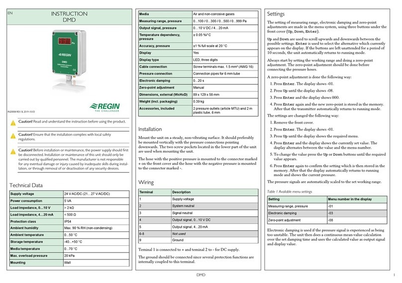
  9. Regin DTT4-420 User manual

Regin DTT4-420 User manual

EN INSTRUCTION
DTT(H)4-420
IN20058 REV. A, 2021-05-17
CCaauuttiioonn Read and understand the instruction before using the product.
CCaauuttiioonn Ensure that the installation complies with local safety
regulations.
CCaauuttiioonn Before installation or maintenance, the power supply should first
be disconnected. Installation or maintenance of this unit should only be
carried out by qualified personnel. The manufacturer is not responsible
for any eventual damage or injury caused by inadequate skills during instal-
lation, or through removal of or deactivation of any security devices.
Function
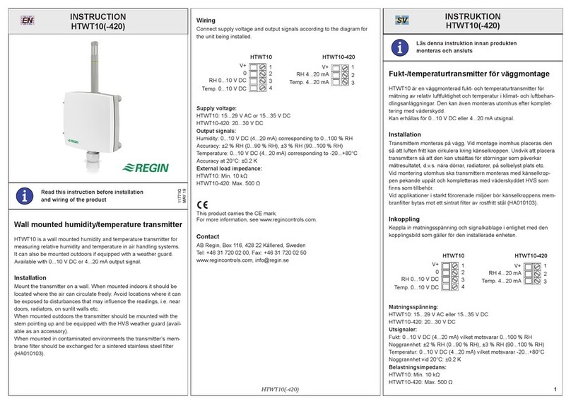
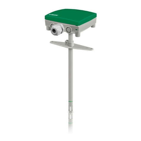
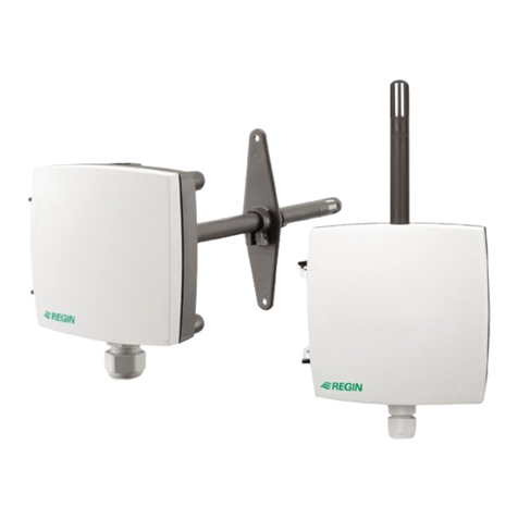
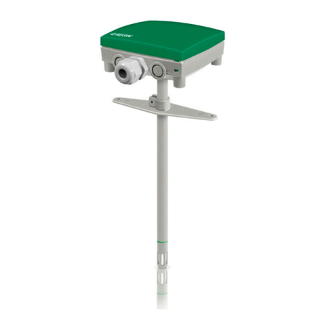
This duct transmitter is used for temperature and humidity
measurements in air. The measurements received can be used to control
ventilation with high precision and improve the air quality in for
example residential and office areas. By increasing the air exchange only
when it is necessary, it is possible to minimise energy costs.
Technical Data
Supply voltage 11+(0.02xRL)…30 V DC
Power consumption < 1 W
Protection class IP65 (housing)
Ambient humidity 0…95 % RH, non-condensing
Ambient temperature -20...+50 °C
Storage temperature -20...+70 °C
Mounting Duct
Insertion length 60…230 mm
Media Air, non-combustible and non-aggressive gases
Measuring range,
temperature
0…50 °C
Output signal,
temperature
4...20 mA (4 mA = 0 °C, 20 mA = 50 °C)
Accuracy,
temperature
±1 K at 20 °C
Measuring range,
humidity
0…100 % RH
Output signal,
humidity
4...20 mA (4 mA = 0 % RH, 20 mA = 100 % RH)
Accuracy, humidity ±3 % RH at 20 °C
Cable gland 1 x M16
Cable connection Screw terminals max. 0.75 mm2
Diameter, probe 12 mm
Dimensions, external
(WxHxD)
75 x 266 x 75 mm
Weight (incl.
packaging)
0.26 kg
Installation
– Find a location in the duct where the transmitter can be expected to
give a representative reading. It should be placed at least 4 duct
diameters from a bend or other obstacle, e.g. a damper, for minimal
turbulence.
– se a 13 mm drill bit to make a hole in the duct
– Remove the 4 screws in the cover to access the terminals
– Place the transmitter in the duct
– Connect the wires to the terminals according to the wiring diagram
under Wiring
– Screw the cover back on and ensure that it is properly fastened and
that the cable gland makes a tight seal around the cable
NNoottee If there is a risk for condensation in the probe, mount the transmit-
ter upright.
Wiring
DTT4-420 DTTH4-420
Figure 1 V+ =11+(0.02xRL)…30 V DC, H and T = 4...20 mA
Settings
Both models are factory calibrated before delivery and do not need to be
calibrated at installation.
This product carries the CE-mark. More information is available at
www.regincontrols.com.
Contact
AB Regin, Box 116, 428 22 Kållered, Sweden
Tel: +46 31 720 02 00, Fax: +46 31 720 02 50
www.regincontrols.com, [email protected]
SE INSTRUKTION
DTT(H)4-420
OObbsseerrvveerraa Läs och förstå instruktionen innan du använder produkten.
OObbsseerrvveerraa Se till att installationen uppfyller lokala
säkerhetsbestämmelser.
OObbsseerrvveerraa Innan installation eller underhåll måste matningsspänningen
först kopplas från. Installation eller underhåll av denna enhet ska endast ut-
föras av kvalificerad personal. Tillverkaren är inte ansvarig för eventuella
skador som orsakas av felaktig installation och/eller inaktivering eller bort-
tagning av säkerhetsanordningar.
Funktion
Denna kanaltransmitter används för temperatur- och relativ
luftfuktighetsmätningar i luft. Mätningarna som erhålls kan användas för
att styra ventilationen med hög precision och förbättra luftkvaliteten i
exempelvis bostads- och kontorslokaler. Genom att endast öka
DTT(H)4-420 1
luftutbytet när det är nödvändigt är det möjligt att minimera
energikostnaderna.
Tekniska data
Matningsspänning 11+(0.02xRL)…30 V DC
Strömförbrukning < 1 W
Skyddsklass IP65 (kapsling)
Omgivande
luftfuktighet
0…95 % RH, icke-kondenserande
Omgivningstempera-
tur
-20...+50 °C
Lagringstemperatur -20...+70 °C
Montage Kanal
Instickslängd 60…230 mm
Media Luft, icke-brännbara och icke-aggressiva gaser
Mätområde,
temperatur
0…50 °C
Utsignal, temperatur 4...20 mA (4 mA = 0 °C, 20 mA = 50 °C)
Noggrannhet,
temperatur
±1 K vid 20 °C
Mätområde, fukt 0…100 % RH
Utsignal, fukt 4...20 mA (4 mA = 0 % RH, 20 mA = 100 % RH)
Noggrannhet, fukt ±3 % RH vid 20 °C
Kabelgenomföring 1 x M16
Kabelanslutning Skruvplintar max. 0,75 mm2
Diameter, givarrör 12 mm
Dimensioner, yttre
(BxHxD)
75 x 266 x 75 mm
Vikt (inkl.
förpackning)
0,26 kg
Installation
– Hitta en plats i kanalen där transmittern kan förväntas ge en
representativ avläsning. Den ska placeras minst 4 kanaldiametrar
från en vinkel eller annat hinder, t.ex. ett spjäll, för minimal
turbulens.
– Använd ett 13 mm borr för att göra ett hål i kanalen
– Avlägsna de 4 skruvarna i locket för att komma åt plintarna.
– Placera transmittern i kanalen
– Anslut kablarna till plintarna enligt inkopplingsschemat under
Inkoppling
– Skruva tillbaka locket och se till att det sitter fast ordentligt och att
kabelgenomföringen sluter tätt runt kabeln
NNootteerraa Montera transmittern upprätt om det finns risk för kondens i
dykröret.
Inkoppling
DTT4-420 DTTH4-420
Figur 1 V+ =11+(0.02xRL)…30 V DC, H ch T = 4...20 mA
Inställningar
Alla modeller är fabrikskalibrerade före leverans och behöver inte
kalibreras vid installation.
Produkten är CE-märkt. Mer information finns på www.regincontrols.
com.
Kontakt
AB Regin, Box 116, 428 22 Kållered, Sverige
Tel: +46 31 720 02 00, Fax: +46 31 720 02 50
www.regincontrols.com, [email protected]
DE INSTALLATIONSANLEITUNG
DTT(H)4-420
VVoorrssiicchhtt Lesen und beachten Sie die Installationsanleitung, bevor Sie das
Produkt verwenden.
VVoorrssiicchhtt Vergewissern Sie sich, dass die Installation den geltenden Sicher-
heitsvorschriften entspricht.
VVoorrssiicchhtt Vor der Installation oder Wartung muss zuerst die Stromversor-
gung unterbrochen werden. Die Installation oder Wartung dieses Geräts
darf nur von qualifizierten Fachkräften durchgeführt werden. Der Herstel-
ler haftet nicht für eventuelle Schäden oder Verletzungen, die durch man-
gelnde Fachkenntnisse bei der Installation oder durch das Entfernen bzw.
Deaktivieren von Sicherheitsvorrichtungen entstehen.
Funktion
Dieser Kanaltransmitter wird für Temperatur- und
Feuchtigkeitsmessungen in der Luft verwendet. Die erhaltenen
Messwerte können eingesetzt werden, um die Lüftung mit hoher
Präzision zu regeln und die Luftqualität, z. B. in Wohn- und
Büroräumen zu verbessern. Da der Luftaustausch nur noch dann erfolgt,
wenn er notwendig ist, werden die Energiekosten auf ein Minimum
reduziert.
Technische Daten
Versorgungsspan-
nung
11+(0,02xRL)…30 V DC
Leistungsaufnahme < 1 W
Schutzart IP65 (Gehäuse)
Umgebungsfeuchte 0...95 % RH, nicht kondensierend
Umgebungstempera-
tur
-20...+50 °C
Lagertemperatur -20...+70 °C
Montage Kanal
Einbaulänge 60...230 mm
Medien Luft, nicht brennbare und nicht aggressive Gase
Messbereich,
Temperatur
0...50 °C
Ausgangssignal,
Temperatur
4...20 mA (4 mA = 0 °C, 20 mA = 50 °C)
Genauigkeit,
Temperatur
± 1 K bei 20 °C
Messbereich ,
Feuchte
0...100 % RH
Ausgangssignal,
Feuchte
4...20 mA (4 mA = 0 % RH, 20 mA = 100 % RH)
Genauigkeit, Feuchte ±3 % RH bei 20 °C
Kabeleinführung 1 x M16
Kabelanschluss Schraubklemmen, max. 0,75 mm2
Durchmesser,
Messelement
12 mm
DTT(H)4-420 2
Abmessungen, au-
ßen (B x H x T)
75 x 266 x 75 mm
Gewicht (inklusive
Verpackung)
0,26 kg
Montage
– Suchen Sie eine Stelle im Kanal, an der der Transmitter
voraussichtlich einen repräsentativen Messwert liefern wird. Er
sollte mindestens in einem Abstand von 4 Kanaldurchmessern nach
einer Krümmung installiert oder einem anderen Hindernis platziert
werden, um Turbulenzen auf ein Minimum zu reduzieren.
– Verwenden Sie einen 13-mm-Bohrer, um ein Loch in den Kanal zu
bohren
– Entfernen Sie die 4 Schrauben in der Abdeckung, um auf die
Klemmen zu gelangen
– Platzieren Sie den Transmitter im Kanal
– Schließen Sie die Drähte an die Klemmen gemäß dem Schaltplan in
Verdrahtung an
– Schrauben Sie die Abdeckung wieder an und vergewissern Sie sich,
dass sie richtig befestigt ist und die Klemmenverschraubung fest um
das Kabel herum abschließt.
HHiinnwweeiiss Wenn die Gefahr von Kondensation im Messelement besteht,
montieren Sie den Transmitter aufrecht.
Verdrahtung
DTT4-420 DTTH4-420
Bild 1 V+ =11+(0,02xRL)…30 V DC, H und T = 4...20 mA
Einstellungen
Beide Modelle sind bei Lieferung werksmäßig kalibriert und brauchen
deshalb nicht bei der Installation kalibriert zu werden.
Dieses Produkt trägt das CE-Zeichen. Weitere Informationen finden Sie
unter www.regincontrols.de.
Kontakt
Regin Controls Deutschland GmbH, Haynauer Str. 49, 12249 Berlin,
Deutschland
Tel.: +49 30 77 99 4-0, Fax: +49 30 77 99 4-79
www.regincontrols.de, [email protected]
FR INSTRUCTION
DTT(H)4-420
AAtttteennttiioonn Veuillez lire attentivement les instructions avant d’utiliser le
produit.
AAtttteennttiioonn Assurez-vous que l’installation est conforme aux normes de
sécurité locales.
AAtttteennttiioonn Avant de procéder à l’installation ou à la maintenance de l’ap-
pareil, il convient de couper l’alimentation électrique. Les opérations d’ins-
tallation et de maintenance doivent être effectuées par un professionnel
qualifié. Le fabricant ne pourra être tenu responsable d’éventuels domma-
ges ou blessures causés par une installation défectueuse du produit, ou
par la désactivation des dispositifs de sécurité.
Fonction
Ce transmetteur en gaine sert à mesurer la température et l'humidité de
l'air. Les mesures relevées permettent de réguler la ventilation avec une
grande précision et d'améliorer la qualité de l'air dans les zones
résidentielles et les bureaux, par exemple. Le fait de pouvoir augmenter
le débit d’air soufflé uniquement lorsque cela est nécessaire permet aussi
de minimiser les coûts énergétiques.
Caractéristiques techniques
Tension
d’alimentation
11+(0.02xRL)…30 V DC
Consommation
électrique
<1 W
Indice de protection IP65 (boîtier)
Humidité ambiante 0...95 % HR (sans condensation)
Température
ambiante
-20...+50°°C
Température de
stockage
-20...+70°C
Montage En gaine
Longueur d’insertion 60…230 mm
Type de fluide Air, Gaz incombustibles non agressifs.
Plage de mesure,
température
0…50 °C
Signal de sortie,
température
4...20 mA (4 mA = 0 °C, 20 mA = 50 °C)
Précision,
température
± 1 K à 20 °C
Plage de mesure,
humidité
0…100 % HR
Signal de sortie,
humidité
4...20 mA (4 mA = 0 % RH, 20 mA = 100 % HR)
Précision, humidité ± 3 % HR à 20 °C
Presse-étoupe 1 x M16
Raccordement de
câble
Borniers à vis max. 0,75 mm2
Diamètre sonde 12 mm
Dimensions, exter-
nes (LxHxP)
75 x 266 x 75 mm
Poids (emballage
inclus)
0,26 kg
Installation
– Cherchez un endroit dans la gaine où le transmetteur peut donner
une mesure représentative. Pour éviter tout dysfonctionnement, il
doit être placé à une distance d'au moins quatre fois le diamètre de
la gaine après un coude ou tout autre obstacle, tel qu'un registre.
– tiliser une mèche de 13 mm pour percer un trou dans la gaine
– Retirer les 4 vis du couvercle pour accéder aux borniers.
– Placer le transmetteur dans la gaine
– Connecter les fils aux borniers selon le schéma de câblage ci-
dessous. Raccordement
– Revisser le couvercle et s'assurer qu'il est bien fixé et que le presse-
étoupe assure une bonne étanchéité autour du câble.
NNBB Si la sonde présente un risque de condensation, monter le transmet-
teur à la verticale.
Raccordement
DTT4-420 DTTH4-420
Fig. 1 V+ =11+(0.02xRL)…30 V DC, H et T = 4...20 mA
DTT(H)4-420 3
Réglages
Tous deux étant calibrés à l'usine, il n'est pas nécessaire de les recalibrer
lors de l'installation.
Ce produit porte le marquage CE. Pour plus d’information, veuillez
consulter le site web www.regincontrols.com.
Contact
Regin France , 32 Rue Delizy, 93500 Pantin, France
Tél. : +33 41 83 02 02, Fax : +33 1 57 14 95 91
www.regincontrols.fr, [email protected]
DTT(H)4-420 4

This manual suits for next models

1

Other Regin Transmitter manuals

Regin TDT200 User manual

Regin

Regin TDT200 User manual

Regin COF User manual

Regin

Regin COF User manual

Regin CO2DT-R User manual

Regin

Regin CO2DT-R User manual

Regin CTRTA User manual

Regin

Regin CTRTA User manual

Regin NO2F User manual

Regin

Regin NO2F User manual

Regin TRT5-420 User manual

Regin

Regin TRT5-420 User manual

Regin DMD User manual

Regin

Regin DMD User manual

Regin Presigo PDT C Series User manual

Regin

Regin Presigo PDT C Series User manual

Regin HTDT2500 User manual

Regin

Regin HTDT2500 User manual

Regin HTWT10 User manual

Regin

Regin HTWT10 User manual

Regin AVDT25 User manual

Regin

Regin AVDT25 User manual

Regin HTRT2500 User manual

Regin

Regin HTRT2500 User manual

Regin CTHRA User manual

Regin

Regin CTHRA User manual

Regin TRTN User manual

Regin

Regin TRTN User manual

Regin DMD-C User manual

Regin

Regin DMD-C User manual

Regin HTDT10 User manual

Regin

Regin HTDT10 User manual

Regin HTRT10A-420 User manual

Regin

Regin HTRT10A-420 User manual

Regin PDTX C Series User manual

Regin

Regin PDTX C Series User manual

Regin DMD User manual

Regin

Regin DMD User manual

Regin HTRT10A-420 User manual

Regin

Regin HTRT10A-420 User manual

Regin DMD-C User manual

Regin

Regin DMD-C User manual

Regin DMD User manual

Regin

Regin DMD User manual

Regin DMD-C User manual

Regin

Regin DMD-C User manual

Popular Transmitter manuals by other brands

Ramsey Electronics TXE433 manual

Ramsey Electronics

Ramsey Electronics TXE433 manual

Phonak TelCom user guide

Phonak

Phonak TelCom user guide

Monacor JTS R-4TBM/5 instruction manual

Monacor

Monacor JTS R-4TBM/5 instruction manual

GE UTX878 Ultrasonic user manual

GE

GE UTX878 Ultrasonic user manual

ABB 2600T Series operating instructions

ABB

ABB 2600T Series operating instructions

Endress+Hauser Liquisys M CUM223 operating instructions

Endress+Hauser

Endress+Hauser Liquisys M CUM223 operating instructions

Williams Sound WIR TX90 Quick setup guide

Williams Sound

Williams Sound WIR TX90 Quick setup guide

Endress+Hauser Liquisys M COM 223 F operating instructions

Endress+Hauser

Endress+Hauser Liquisys M COM 223 F operating instructions

Magtech LTM-250 instruction & operation manual

Magtech

Magtech LTM-250 instruction & operation manual

Konig VID-TRANS150KN manual&nbsp;

Konig

Konig VID-TRANS150KN manual&nbsp;

Sekonic RT-20PW operating manual

Sekonic

Sekonic RT-20PW operating manual

BWI Eagle AIR-EAGLE XLT 441P-HH-4-002-CL Product information bulletin

BWI Eagle

BWI Eagle AIR-EAGLE XLT 441P-HH-4-002-CL Product information bulletin

Stingray 418ELPW V Series manual

Stingray

Stingray 418ELPW V Series manual

DMP 1106E Series installation guide

DMP

DMP 1106E Series installation guide

HumanTechnik RadioLight operating instructions

HumanTechnik

HumanTechnik RadioLight operating instructions

ARTEX ELT 4000S Description, operation, installation and maintenance manual

ARTEX

ARTEX ELT 4000S Description, operation, installation and maintenance manual

Vaisala HUMICAP MMT310 user guide

Vaisala

Vaisala HUMICAP MMT310 user guide

Tactical technologies TX-600 Operating	 instruction

Tactical technologies

Tactical technologies TX-600 Operating instruction

manuals.online logo
manuals.online logoBrands
  • About & Mission
  • Contact us
  • Privacy Policy
  • Terms and Conditions

Copyright 2025 Manuals.Online. All Rights Reserved.