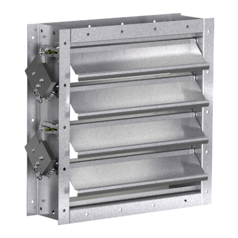
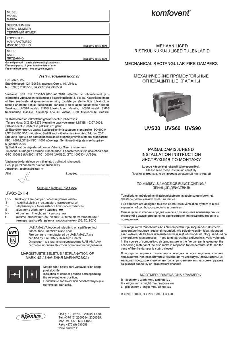
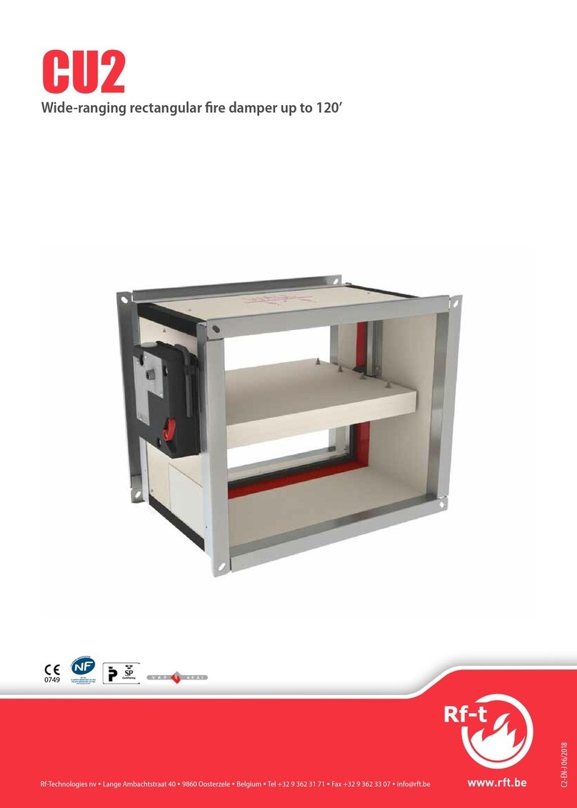
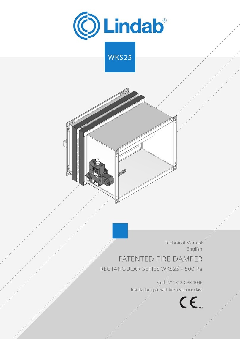
Rf-t CA2 User manual

www.rft.be
en
Rf-Technologies nv Lange Ambachtstraat 40 9860 Oosterzele Belgium Tel +32 9 362 31 71 Fax +32 9 362 33 07 [email protected]
C4-G 01/2017
CA2
Rectangular surface-mounted re damper 60'

2Table of content
Table of content
Declaration of performance 3
Product presentation CA2 4
Range and dimensions CA2 4
Variant CA2L 4
Range and dimensions CA2L 5
Evolution - kits 5
Options - at the time of order 9
Flange types - at the time of order 10
Storage and handling 12
Installation 12
Installation in rigid wall 13
Operation and mechanisms 14
Electrical connection 20
Weights 24
Selection graphs 27
Example 27
Selection data 28
Correction factor ΔL 31
Sample order 32
Approvals and certificates 32
Explanation of the abbreviations and pictograms
Wn = nominal width
Hn = nominal height
Dn = nominal diameter
E = integrity
I = thermal insulation
S = smoke leakage
Pa = pascal
ve = vertical wall penetration
ho = horizontal floor penetration
o -> i = meets the criteria from the outside
(o) to the inside (i)
i <-> o = fire side not important
V AC = Volt alternating current
V DC = Volt direct current
E.ALIM = power supply magnet
E.TELE = power supply motor
V = volt
W = watt
Auto = automatic
Tele = remote controlled
Pnom = nominal capacity
Pmax = maximum capacity
GKB (type A) / GKF (type F): "GKB" stands
for standard plasterboards (type A accor-
ding to EN 520) while "GKF" plasterboards
offer a higher fire resistance for a similar
plate thickness (type F according to EN
520)
Cal-Sil = calcium silicate
OP = option (delivered with the product)
KIT = kit (delivered separately for repair or
upgrade)
PG = connection flange to the duct
Sn = free air passage
ζ [-] = pressure loss coefficient
Q = air flow
∆P = static pressure drop
v = air speed in the duct
Lwa = A-weighted sound power level
Lw oct = sound power level per octave
midband
dB(A)a = A-weighted decibel value
∆L = correction factor
fast installation suitable for surface-mount
intermediate dimensions on request

3
Declaration of performance
D-01/2017CE_DoP_Rf-t_C4_EN
DECLARATION OF PERFORMANCE
Declarationofperformance
CE_DoP_Rf-t_C4_EN
D-01/2017
1. Unique identication code of the product-type: CA2
2. Intended use/es: Rectangular re damper to be used in conjunction with partitions to maintain re compartments in heating, ventilating and air conditioning installations.
3. Manufacturer: Rf-Technologies NV, Lange Ambachtstraat 40, B-9860 Oosterzele
4. System/s of AVCP: System 1
5. Harmonised standard / European Assessment Document; notied body / European
Technical Assessment, Technical Assessment Body, notied body; certicate of
constancy of performance:
EN 15650:2010, BCCA with identication number 0749; BC1-606-0464-15650.07-0464
6. Declared performance according to EN 15650:2010 (Fire resistance according to EN 1366-2 and classications according to EN 13501-3)
Essential characteristics Performance
Range Wall type Wall Sealing Installation Classication
200x200 mm ≤ CA2 ≤
700x700 mm
Rigid wall Aerated concrete ≥ 100mm Not applicable 1 EI 60 (vei no) S - (500 Pa)
1 Type of installation: surface-mounted, 0/180°
Nominal activation conditions/sensitivity: Pass
Response delay (response time): closure time Pass
Operational reliability: cycling
CFTH - 50 cycles; MANO - 300 cycles; B(L)
F(T) - 10000 cycles; BFL(T) - 10000 cycles;
BFN(T) - 10000 cycles; ONE - 10000 cycles;
UNIQ - 300 cycles
Durability of response delay: Pass
Durability of operational reliability: Pass
Protection against corrosion according to EN 60068-2-52: Pass
Damper casing leakage according to EN 1751: ≥ class B
Harmonised standard
EN 15650:2010
The performance of the product identied above is in conformity with the set of declared performance/s.This declaration of
performance is issued, in accordance with Regulation (EU) No 305/2011, under the sole responsibility of the manufacturer identi-
ed above.
Signed for and on behalf of the manufacturer by:
Barbara Willems, Technical Manager
Oosterzele, 01/2017
4Product presentation CA2
Product presentation CA2
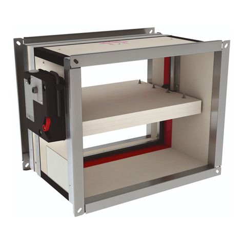
Rectangular surface-mounted fire damper with a 60 minutes fire resistance on concrete walls. The CA2 damper is particularly suited
for building sites where access to the damper is difficult or impossible from one side of the wall. The refractory casing is abestos free
and resistant to humidity.
Fire dampers are installed where air ducts penetrate fire-resistant compartment walls. Their role is to restore the fire resistance grade
of the penetrated wall and to prevent smoke propagation. Fire dampers are distinguished by their degree of fire resistance, by their
aeraulic properties as well as by their installation ease. Rf-Technologies' fire dampers are all CE marked. They can be equipped with
various types of mechanisms depending on the specific needs linked to the project or to the local regulations.
5fast installation
5ideal as a terminal damper
∎tested according to EN 1366-2 up to 500 Pa
∎suitable for surface-mounting on rigid wall
∎operating mechanism outside the wall
∎maintenance-free
∎for indoor use
∎suitable for surface-mount
∎intermediate dimensions on request
1. connection flange PG30
2. casing made of refractory material
3. damper blade
4. operating mechanism
5. sealing cold smoke
6. blade bumper
7. intumescent strip
8. transmission with locking (open/closed)
9. fixing frame
10.fusible link
11. product identification
9
6
3
4
8
27
5
10
1
11
Range and dimensions CA2
Exceeding blade: X = on the mechanism side, Y = on the wall side
XY
45
125mm240mm
365mm
(Wn+165)x(Hn+165)
(Wn+88)x(Hn+88)
(Wn-6)x(Hn-6)
Hn [mm] 250 300 350 400 450 500 550 600 650 700
x - - - - - - 1 26 51 76
y 12 37 62 87 112 137 162 187 212 237
≥ ≤
(Wn x Hn)
mm 200x200 700x700

5
Range and dimensions CA2L
Variant CA2L
Damper with a tunnel casing extension at one or both sides so that the damper blade does not exceed the tunnel. This version allows
to connect a grill or a bend directly on the damper flange or to use a circular connection.
∎extension: a=Hn/2-230 mm (on the side of the mechanism);
b=Hn/2-100 mm (on the wall side)
227,5+a 102,5+b
L
Range and dimensions CA2L
Exceeding blade: X = on the mechanism side, Y = on the wall side
102,5+b
227,5+a
yx
55/65
(Hn-6) x (Wn-6)
L=330+x+y
≥ ≤
(Wn x Hn)
mm 200x200 700x700
Hn < 300 mm Hn ≥ 300 mm
P
Z
Q
Ln P
ZQ
Ln
CFTH ONE BFL(T) UNIQ
P78 104 96 114
Q180 191 110 290
Z62 47 74 47
CFTH ONE BFL(T) BFN(T) UNIQ
P78 104 96 100 114
Q180 191 110 110 290
Z157 147 180 180 147

6Evolution - kits
Evolution - kits
KITS CFTH Automatic unlocking mechanism CFTH with FCU and without FTH 72
KITS MANO EVO Upgradeable automatically unlocking mechanism
KITS BFL24 Spring return actuator BFL 24V
KITS BFL24-ST Spring return actuator BFL 24V with plug (ST)
KITS BFLT24 Spring return actuator BFL 24V with thermo-electric fuse (T)
KITS BFLT24-ST Spring return actuator BFL 24V with thermo-electric fuse (T) and plug (ST)
KITS BFL230 Spring return actuator BFL 230V
KITS BFLT230 Spring return actuator BFL 230V with thermo-electric fuse (T)
KITS BFN24 Spring return actuator BFN 24V (BFN kits must be used instead of BFL kits for fire dampers
produced before 1/7/2015)

7
Evolution - kits
KITS BFN24 Spring return actuator BFN 24V
KITS BFN24-ST Spring return actuator BFN 24V with plug (ST)
KITS BFNT24 Spring return actuator BFN 24V with thermo-electric fuse (T)
KITS BFNT24-ST Spring return actuator BFN 24V with thermo-electric fuse (T) and plug (ST)
KITS BFN230 Spring return actuator BFN 230V
KITS BFNT230 Spring return actuator BFN 230V with thermo-electric fuse (T)
KITS BF24 Spring return actuator BF 24V (BF kits must be used instead of BFN kits for fire dampers
produced before 1/7/2015)
KITS ONE T 24 FDCU Spring return actuator ONE 24V (with fusible link T) + unipolar beginning- and end-of-ran-
ge switch
KITS ONE T 24 FDCB Spring return actuator ONE 24V (with fusible link T) + bipolar beginning- and end-of-ran-
ge switch

8Evolution - kits
KITS ONE T 230 FDCU Spring return actuator ONE 230V (with fusible link T) + unipolar beginning- and end-of-
range switch
KITS ONE T 230 FDCB Spring return actuator ONE 230V (with fusible link T) + bipolar beginning- and end-of-ran-
ge switch
UNIQ VD/VM FDCU Operating mechanism UNIQ (with fusible link) + unipolar beginning- and end-of-range
switch
UNIQ VD/VM FDCB Operating mechanism UNIQ (with fusible link) + bipolar beginning- and end-of-range
switch
KITS VD24 MAN EVO FDCU Natural magnet 24 V DC + FDCU
KITS VD48 MAN EVO FDCU Natural magnet 48 V DC + FDCU
KITS VM24 MAN EVO FDCU Electromagnet 24 V DC + FDCU
KITS VM48 MAN EVO FDCU Electromagnet 48 V DC + FDCU
KITS FDC CFTH 1 Beginning or end of range switch FCU/DCU/FCB/DCB
KITS FDCU MAN Unipolar beginning and end of range switch

9
Options - at the time of order
KITS FDCB MAN Bipolar beginning and end of range switch
KITS SN2 BFL/BFN Bipolar beginning and end of range switch
KITS ME MANO EVO Resetting motor ME 24V/48V (AC, DC)
KITS ME UNIQ Resetting motor ME 24V/48V (AC, DC)
KITS FTH72 Fusible link FTH 72°C (for CFTH)
KITS FT72 MANO EVO Fusible link FTH 72°C
KITS ZBAT 72 Black spare part for thermo-electric fuse for BFLT/BFNT
FUS72 ONE Fusible link 72°C
FUS72 UNIQ Fusible link 72°C
MECT Testbox for mechanisms (magnet, motor, beginning and end of range switches)

10 Flange types - at the time of order
Options - at the time of order
UL Inspection shutter (set of 2)
EN 1751
C
EN1751_C Air-tightness class C
Flange types - at the time of order
33
30 30
3333
400
HnxWn
(Hn-6)x(Wn-6)
PG30 Connection to ducts with 30 mm flanges (either by sliding profile, or with bolts, or with
clamps). Elliptical holes Ø 8,5 x 16 mm.
43 43
400
4040
43
HnxWn
(Hn-6)x(Wn-6)
PG40 Connection to ducts with 40mm flanges. Elliptical holes Ø 8,5 x 16mm.
23
2020
400
23 23
HnxWn
(Hn-6)x(Wn-6)
PG20 Connection to ducts with 20 mm flanges. Elliptical holes Ø 6,5 x 16m.
40
HnxWn
(Hn-6)x(Wn-6)
L-70
PM Connection to ducts by insertion. This type of frame is used in case of lack of space for a
standard PG30 frame.
(Hn-6)x(Wn-6)
+L-70
PP No connection. This type of frame is used on one side of a damper that ends into a room.
Øn-2
e L
L1
e
n+30
PR Circular connection on a rectangular damper.

11
Flange types - at the time of order
Øn-2
e L
L1
e
n+30
PRJ Circular connection with rubber sealing ring.
210
W+62
H+62
PPT Grill. Very well suited as protection grill on the end piece of a duct system.

12 Storage and handling
Storage and handling
As this product is a safety element, it should be stored and handled with care.
Avoid:
• any kind of impact or damage
• contact with water
• deformation of the casing
It is recommended:
• to unload in a dry area
• not to flip or roll the product to move it
• not to use the damper as a scaffold, working table, etc.
• not to store smaller dampers inside larger ones
Installation
General points
∎The installation must comply with the installation manual delivered with the product and the classification report.
∎Axis orientation: see the declaration of performance.
∎Avoid obstruction of adjoining ducts.
∎Product installation: always with closed damper blade.
∎Verify if the blade can move freely.
∎Please observe safety distances with respect to other construction elements.
∎The air tightness class will be maintained if the damper is installed according to the installation manual.
∎Rf-t fire dampers are always tested in standardised constructions according to EN 1366-2. The achieved results are valid for similar
supporting constructions with a fire resistance, thickness and density equal or superior to the supporting construction used
during the test.
∎The damper must remain accessible for inspection and maintenance.
∎Schedule at least two running checks each year.
2015
2016
2017
2018
2019
TEST
|
|
|
|
|
≥ 75mm
≥ 75mm ≥ 200mm ≥ 200mm

13
Installation
Installation in rigid wall
The product was tested and approved in:
Range Wall type Sealing Classication
200x200 mm ≤ CA2 ≤ 700x700 mm Rigid wall Aerated concrete ≥ 100mm Not applicable EI 60 (vei no) S - (500 Pa)
Wn x Hn (mm)
Provide a minimal installation opening in the wall = (Wn x Hn)
mm.
Mount the damper on the wall around the opening. As the
mechanism needs to be accessible at all times, you need to pro-
vide a free working space of min. 200 mm. The damper exceeds
the wall from 365mm at the mechanism side.
If the mechanism is not accessible you need to provide an in-
spection shutter (e.g. false ceiling). Affix the damper in the wall
with the bolts provided.
No further sealing required.
Check the mobility of the damper blade.
TEST!
Check the mobility of the blade.
Maintenance
∎No specific maintenance required.
∎Schedule at least two running checks each year.
∎Remove dust and all other particles before start-up.
∎Follow the local maintenance regulations (i.e. BS9999 Annex V; NF S 61-933) and EN13306.
∎Read the maintenance instructions on our website: http://www.rft.be/Upload/main/Brochures%20Marketing/NT-K136%20Mainte-
nance%20C.pdf

14 Operation and mechanisms
Operation and mechanisms
CFTH Automatically unlocking mechanism
The unlocking mechanism CFTH automatically unlatches the damper blade when the temperature in the duct rises above 72°C. The
damper can also be unlocked and reset manually.
1. unlocking button
2. resetting handle
3. cable entrance
1
3
2
Options - at the time of order
FCU Unipolar end of range switch
DCU Unipolar beginning of range switch (order with FCU)
FCB Bipolar end of range switch
DCB Bipolar beginning of range switch (order with FCB)
Unlocking
∎manual unlocking: use the unlocking button (1).
∎automatic unlocking: when the fusible link melts at 72° C.
∎remote unlocking: n/a
Resetting
∎manual resetting: use the enclosed Hex key and turn clockwise(2).
∎motorised resetting: n/a
Caution:
The mechanism may never be tested on its own, without being attached to the damper. Such a test might damage the me-
chanism or the operator might be injured.

15
Operation and mechanisms
ONE Spring return actuator for remote control
The spring-return actuator ONE is designed to easily operate Rf-t fire dampers of all sizes, automatically or remotely.Five models are
available, 24 or 230 volt, with FDCU or FDCB position switches; and 24 volt with plug (ST).
1. unlocking button
2. blade position indicator
3. LED
4. battery compartment to reset motor
5. plug (ST)
2
1
3
4
5
Options - at the time of order
IXI-R1 Universal field controller (Modbus, BACnet or analog connection), pre-mounted on the damper.
IXI-R2 Universal field controller (Modbus, BACnet), pre-mounted on the damper and with a connection for a second
damper.
Unlocking
∎manual unlocking: shortly press the unlocking button (1) once.
∎automatic unlocking: the fusible link reacts as soon as the temperature in the duct reaches 72°C.
∎remote unlocking: by interrupting the power supply.
Resetting
∎manual resetting: open the battery compartment (4) and press a 9V battery against the contact springs. Hold this position until
the LED (3) emits a continuous light. Check whether the indicator (2) shows that the damper blade is in the open position. Remove
the battery, the LED fades away. Close the battery compartment.
∎motorised resetting: switch off the power supply for at least 5 sec. Power the actuator (respect the prescribed voltage) for at least
75 sec. The resetting stops automatically when the end of range is reached (damper open).
Caution:
If the LED (3) flickers fast (3x/sec.), the battery is discharged: use a new battery.
If the LED (3) flickers slowly (1x/sec.), the resetting is in progress.
If the LED (3) is continuously on, the resetting is complete and the motor is powered.
If the actuator detects voltage on the power cable, a brief contact of the battery is enough to start the resetting process.
The power supply of this actuator cannot be individually replaced. If the cable is damaged, the whole unit must be discarded
and replaced.
The housing of the mechanism contains a temperature sensor. When the temperature in the housing exceeds 72°C, the
mechanism unlocks. The LED flashes twice per second. When the temperature drops below 72°C, the mechanism can only be
reset in a motorised manner after a manual reset (with a battery).
The end of range switches need 1 second after operation to adopt a stable position.

16 Operation and mechanisms
UNIQ Upgradeable operating mechanism for remote control
Compliant with NF S 61-937, the UNIQ operating mechanism is designed to operate Rf-t fire dampers of all sizes, easily and remotely.
Four models are available: with FDCU or FDCB position switches and with or without ME resetting motor. All models are dual-voltage
24/48V and with an electrical impulse triggering (VD) with a possibility to change to power interruption triggering (VM) by removing
a jumper.
1. unlocking button
2. blade position indicator
3. LED
4. battery compartment to reset motor
5. connection compartement
2
5
1
3
4
Unlocking
∎manual unlocking: shortly press the unlocking button (1) once.
∎automatic unlocking: the fusible link reacts as soon as the temperature in the duct reaches 72°C.
∎remote unlocking: by sending an electrical impulse (VD) or by interrupting the power supply (VM) to the magnet connection.
Resetting
∎manual resetting: open the battery compartment (4) and press a 9V battery against the contact springs. Hold this position until
the LED (3) stops flickering. Check whether the indicator (2) shows that the damper blade is open. Remove the battery and close
the battery compartment.
∎motorised resetting: switch off the power supply to the motor (ME) connection for at least 5 sec. Power the ME motor (respect the
prescribed voltage) for at least 45 sec. The resetting stops automatically when the end of range is reached (damper open).
Caution:
If the LED (3) flickers fast (3x/sec.), the battery is discharged: use a new battery.
If the LED (3) flickers slowly (1x/sec.), the resetting is in progress.
After the reset, the LED reflects the status of the magnet: Magnet powered = LED lit; no power supply to magnet = LED off
The housing of the mechanism contains a temperature sensor. When the temperature in the housing exceeds 72°C, the
mechanism unlocks. The LED flashes twice per second. When the temperature drops below 72°C, the mechanism can only be
reset in a motorised manner after a manual reset (with a battery).
Caution:
Connect the mechanism according to the wiring diagram and NF S 61-932.
When connecting the cables, it is necessary to use the cable-ties, as shown in the drawing included in the bag containing the
cable-ties.

17
Operation and mechanisms
MANO EVO Upgradeable automatically unlocking mechanism
The fusible link of the upgradeable unlocking mechanism MANO EVO automatically unlatches the damper blade when the tempe-
rature in the duct rises above 72°C. It is easy to upgrade the automatic MANO EVO mechanism into a remote controlled mechanism
(remote electrical unlocking) or into a motorised mechanism (remote resetting).
1. unlocking button
2. resetting handle
3. cable entrance
2
1
3
Options - at the time of order
VD24 Natural magnet 24 VDC (order with FDCU)
VD48 Natural magnet 48 V DC (order with FDCU)
VM24 Electromagnet 24 V DC (order with FDCU)
VM48 Electromagnet 48 V DC (order with FDCU)
FDCU Unipolar beginning and end of range switch
FDCB Bipolar beginning and end of range switch (incl. FDCU)
ME Resetting motor ME 24V/48V (AC, DC)
Unlocking
∎manual unlocking: use the unlocking button (1).
∎automatic unlocking: when the fusible link melts at 72° C.
∎remote unlocking: (option VD/VM MAN EVO FDCU) by sending an electrical impulse (VD) or by interrupting the power supply
(VM) to the magnet.
Resetting
∎manual resetting: turn 90° clockwise with a Torcq key 13 mm (2).
∎motorised resetting: (option ME MANO EVO) switch off the power supply for at least 10 sec. Power the actuator for at least 30 sec.
(respect the prescribed voltage and polarity). The resetting stops automatically if a torque > 15 Nm is detected.
Caution:
Switch off the power supply after resetting.
Switch off the power supply for at least 15 sec. in between each resetting cycle.
Caution:
The mechanism may never be tested on its own, without being attached to the damper. Such a test might damage the me-
chanism or the operator might be injured.

18 Operation and mechanisms
BFL(T) Remotely controlled spring return actuator
The spring return actuator BFL(T) is specially designed to remotely control fire dampers. The BFL(T) model is intended for fire dam-
pers with smaller dimensions (ø ≤ 400 mm or W+H ≤ 1200 mm/1400 mm for CU-LT, CU-LT-1s).
1. locking button
2. plug (ST)
3. access for manual resetting
4. thermo-electric tripping device (T)
1
3
4
2
Options - at the time of order
SN2 BFL/BFN Bipolar beginning and end of range switch
IXI-R1 Universal field controller (Modbus, BACnet or analog connection), pre-mounted on the damper.
IXI-R2 Universal field controller (Modbus, BACnet), pre-mounted on the damper and with a connection for a second
damper.
Unlocking
∎manual unlocking: place the locking button on “unlock”. (In case of BFLT: the damper can alternatively be unlocked by pushing
the “test” button on the thermo-electric fuse)
∎automatic unlocking: the thermo-electric fuse reacts as soon as the temperature reaches 72°C (type BFLT).
∎remote unlocking: by interrupting the power supply.
Caution:
The thermo-electric fuse will not move the damper into its safety position (when the temperature reaches 72°C) if the motor
is not powered.
Resetting
∎manual resetting: turn the enclosed handle anti-clockwise. To block the motor, place the locking button on “lock”
∎motorised resetting: switch off the power supply for at least 10 seconds. Supply the actuator (respect the prescribed voltage) for
at least 75 seconds. The resetting stops automatically when the end of range is reached (damper open) - it takes about 60 seconds
to reset the damper - or when the power supply is interrupted.
Caution:
Do not use a drill or screwing machine.
Stop as soon as the motor is completely rearmed (end of range).
prod. < 1/7/2015
prod. ≥ 1/7/2015
CR60(1s)
CR120
CU-LT
CU-LT-1s
CR2≤400
CU2≤1200
CR2>400
CU2>1200
CR60(1s)
CR120
CU-LT
CU-LT-1s
CR2≤400
CU2≤1200
CR2>400
CU2>1200
Kit BFL
Kit BFN
Kit BF

19
Operation and mechanisms
BFN(T) Remotely controlled spring return actuator
The spring return actuator BFN(T) is specially designed to remotely control fire dampers. The BFN(T) model is intended for fire dam-
pers with large dimensions (ø > 400 mm (CR2) or W+H > 1200 mm (CU2, CA2, CU2_15, CU4)) or for dampers CU-LT(-1s), CR60, CR120
with a production date before 1 July 2015.
1. locking button
2. plug (ST)
3. access for manual resetting
4. thermo-electric tripping device (T)
1
3
4
2
Options - at the time of order
SN2 BFL/BFN Bipolar beginning and end of range switch
IXI-R1 Universal field controller (Modbus, BACnet or analog connection), pre-mounted on the damper.
IXI-R2 Universal field controller (Modbus, BACnet), pre-mounted on the damper and with a connection for a second
damper.
Unlocking
∎manual unlocking: place the locking button on “unlock”. (In case of BFNT: the damper can alternatively be unlocked by pushing
the “test” button on the thermo-electric fuse)
∎automatic unlocking: the thermo-electric fuse reacts as soon as the temperature reaches 72°C (type BFNT).
∎remote unlocking: by interrupting the power supply.
Caution:
The thermo-electric fuse will not move the damper into its safety position (when the temperature reaches 72°C) if the motor
is not powered.
Resetting
∎manual resetting: turn the enclosed handle anti-clockwise. To block the motor, place the locking button on “lock”
∎motorised resetting: switch off the power supply for at least 10 seconds. Supply the actuator (respect the prescribed voltage) for
at least 75 seconds. The resetting stops automatically when the end of range is reached (damper open) - it takes about 60 seconds
to reset the damper - or when the power supply is interrupted.
Caution:
Do not use a drill or screwing machine.
Stop as soon as the motor is completely rearmed (end of range).

20 Electrical connection
Electrical connection
CFTH ONE UNIQ
FCU
1211
10
DCB
NONFC
15 1614
13
FCB
NONFC
987
56
DCU
NONFCNONFC
DC FC
24VDC
24VAC
230VACN L
65
4
3
12
6543
12
M
BK RD
DC : Switch open position re damper
FC : Switch closed position re damper
violet
red
white
orange
pink
grey
FCB
DCB
ME
16
NO
15
NF
14
C
13
NO
12
NF
11
C
FCU
DCU
10
NO
9
NF
8
C
7
NO
6
NF
5
C
1
+ –
2
24/48 VDC
VD/VM
3
+ –
4
24/48 VDC
24 VAC
VD
VM
VD : unlocking through electrical impulse
(with jumper)
VM : unlocking through power interruption
DCU : Unipolar beginning of range switch
FCU : Unipolar end of range switch
DCB : Bipolar beginning of range switch
FCB : Bipolar end of range switch
ME : Resetting motor
MANO EVO BFL(T) BFN(T)
-
+
1211
10 15 1614
139875 6
34
12
+/
24/48 V DC +/- 10%
24/48 V AC +/- 10%
24 V DC
48 V DC
FCU DCB
NONFC
FCB
NONFC
DCU
NONFCNONFC
ME
-+ -/
FCU
S6S5
S4
DCU
<5° <80°
NONFC
S3S2S1
12
ME
NONF
24VDC
24VAC
230VACN L
C
FCU
S6S5
S4
DCU
<5° <80°
NONFC
S3S2S1
12
ME
NONF
24VDC
24VAC
230VACN L
C
Table of contents
Other Rf-t Fire And Smoke Damper manuals
Popular Fire And Smoke Damper manuals by other brands

Broan
Broan MD6T user manual

Greenheck
Greenheck FD Series Installation instruction supplement

BSB
BSB FSD-C Installation, operating, & maintenance instructions

VPro
VPro WT Series instruction manual

Helios
Helios BRK Installation and operating instructions

Greenheck
Greenheck DFD Series Installation, operation and maintenance manual