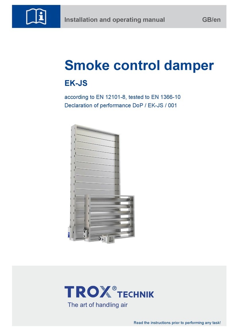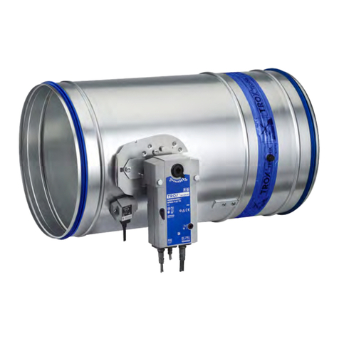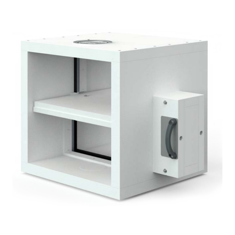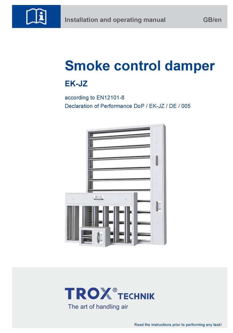
Smoke control dampers
Specification text
08/2017
EK-JZ
– DE/en
This specification text describes the general
properties of the product.Texts for variants can be
generated with our Easy Product Finder design
programme.
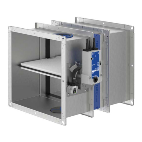
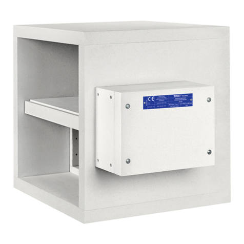
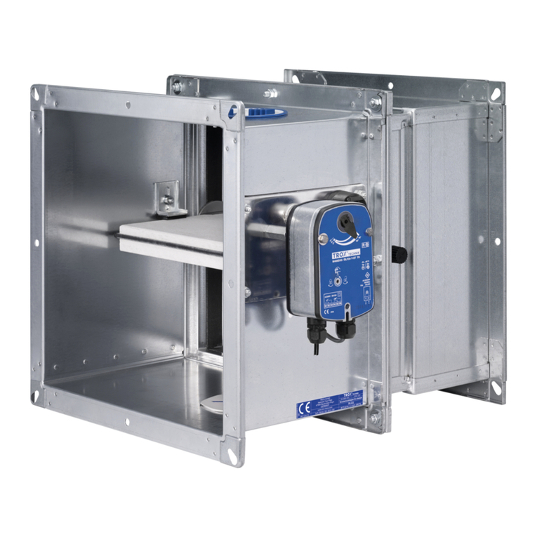
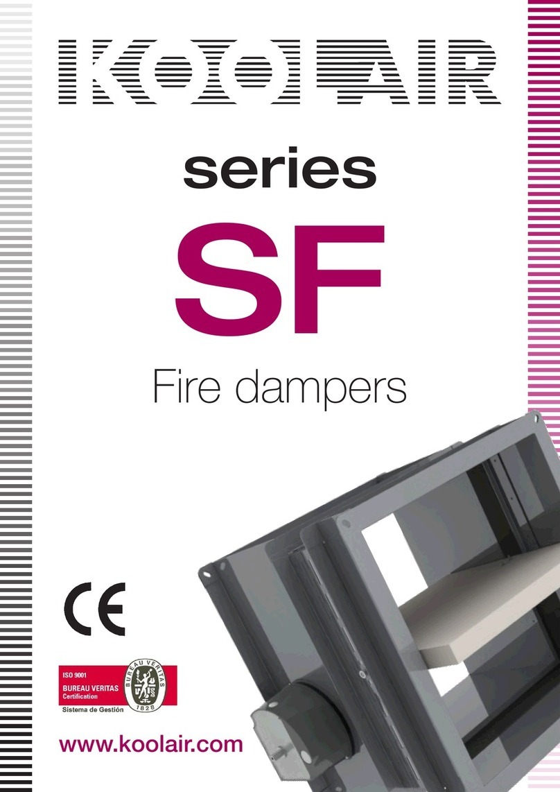
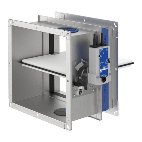
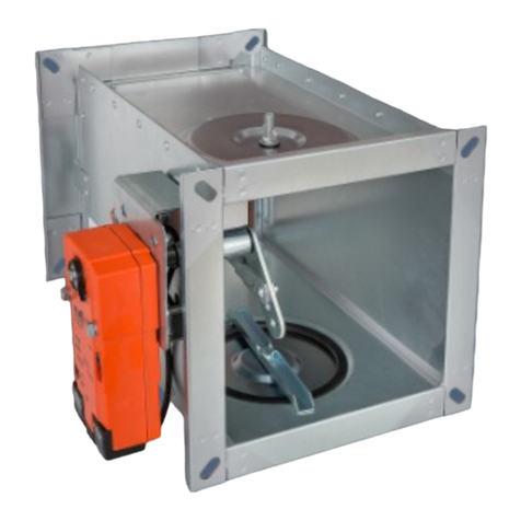
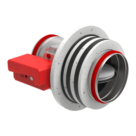
Rectangular or square smoke control dampers to
product standard EN 12101-8, tested to EN 1366-
10 and EN 1366-2, for use in smoke extract
systems. Smoke control dampers are not only
used for the exhaust of smoke, heat and
combustion products, but also for the controlled
removal of dangerous and toxic fire suppression
gases.
EK-JZ smoke control dampers can also be used
in pressurisation systems and as pressure relief
dampers in gas fire extinguishing systems. Also
for extracting smoke gases and for providing
additional supply air to one or more fire
compartments.
EK-JZ can be used in combined smoke exhaust
systems which have been approved for controlled
ventilation.The fire-resistant smoke control
damper for multiple compartments is suitable for
installation in and on fire-resistant smoke extract
ducts and in fire-resistant standard supporting
constructions. It is controlled with open/close
actuators that can be combined with control
modules that are factory wired and fitted inside
the temperature-resistant actuator encasing.
Classification
– EI 120/90 (vedw, i ↔ o) S1000 C10,000 MA multi
Special characteristics
– C10,000 for combined smoke extract and
ventilation systems
– Complies with the requirements of EN 12101-8
– Tested to EN 1366-2 and 1366-10 for fire
resistance properties
– Closed blade air leakage to EN 1751, class 3,
and casing air leakage to EN 1751, class C
– Low sound power level and differential
pressure
– Any airflow direction
– Manual release is also possible using
TROXNETCOM
– Integration into the central BMS with standard
bus systems
– Long-time testing to EN 1366-10 with a weight
being attached to the blades, 10,000 open/
close cycles
Materials and surfaces
– Casing, damper blade and actuator encasing
made of temperature-resistant calcium silicate
– Brass bearings
– Blade shafts, drive arm and external linkage
made of galvanised steel
Technical data
– Nominal sizes B × H:
200 × 430 mm – 1200 × 2030 mm
– Casing length: 250 mm
– Volume flow rate range: Up to 24361 l/s or
87700 m³/h
– Differential pressure range, pressure level 2:
–1000 to 500 Pa
– Operating temperature: –30 to 50 °C; the
temperature should not fall below the dew point
– Upstream velocity*: ≤ 10 m/s with the largest
size, > 10 – 15 m/s with smaller sizes;
87700 m³/h max.
* Data applies to uniform upstream and
downstream conditions for the smoke control
damper
Attachments
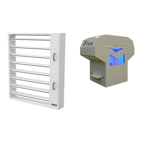
Connecting subframe and cover grille for the
operating side and/or installation side.
– Connecting subframe for calcium silicate and
sheet steel smoke extract ducts
– Cover grille – crimped wire mesh or square
perforated metal plate
– Cover grille – external weather louvre or
ventilation grille
Open/Close actuators for the control of smoke
control dampers, with automatic (AA) or manual
release (MA).
Optional control or communication module for
integration with the central BMS.
– Supply voltage 24 V AC/DC or 230 V AC
– Limit switches for capturing the end positions
OPEN and CLOSED
– Override control for up to 25 minutes
– Module for the control of smoke control
dampers (optional)
– Indicator lights for indicating the damper blade
position
– Monitoring of signal reception
Sizing data
– ____________ _______________________
[m³/h]
– Δpst __________ _______________________
[Pa]
Air-regenerated noise
– LPA ___________ _______________________
[dB(A)]
PD – EK-JZ – 16


