Ricoh SR400 User manual

FINISHER
(Machine Code:A379)

1. OVERALL MACHINE INFORMATION
1.1 SPECIFICATIONS
Paper Size: Maximum: 11" x 17"/A3
Minimum: 51/2" x 81/2"/A5 sideways
Paper Weight: Standard copying/Stack mode
14 ~ 42 lb/52 ~ 157 g/m2
Staple mode
17 ~ 20 lb/64 ~ 80 g/m2
Paper Capacity: 1,500 sheets:
81/2" x 11"/A4 or smaller size (20 lb/80 g/m2)
1,000 sheets:
81/2" x 14"/B4 or larger size (20 lb/80 g/m2)
Stapler Capacity: 81/2" x 11"/A4 or smaller size (20 lb/80 g/m2):
from 2 to 50 sheets
81/2" x 14"/B4 or large size (20 lb/80 g/m2):
from 2 to 30 sheets
Staple Replenishment: Cartridge exchange (5,000 pieces/cartridge)
Power Source: DC 24 V (from copier)
Power Consumption: 44.4 W (average)
Weight: 34.2 kg (75.4 lb)
Finisher
23 April 1993 OVERALL MACHINE INFORMATION
1

Stapling Position:
Dimensions: 26.4" x 20.2" x 37.4"
(671 mm x 514 mm x 950 mm)
Weight: 75.2 lb/34.2 kg
a
b
aa
b
b
a = 0.24" ±0.12" (6 ±3 mm)
b = 0.24" ±0.12" (6 ±3 mm) a = 0.24" ±0.12" (6 ±3 mm)
b = 5.20" ±0.12" (13.2 ±3 mm)
(1 staple)
(2 staples)
OVERALL MACHINE INFORMATION 23 April 1993
2

1.2 MECHANICAL COMPONENT LAYOUT
8
7
5
6
12
11
9
10
113
4
2
3
1. Stack Height Sensor Feeler
2. Shift Tray
3. Shift Tray Positioning Roller
4. Jogger Unit
5. Positioning Roller
6. Stack Feed-out Belt
7. Stapler Unit
8. Alignment Brush Roller
9. Lower Transport Rollers
10. Entrance Rollers
11. Junction Gate
12. Upper Transport Rollers
13. Exit Rollers
Finisher
23 April 1993 OVERALL MACHINE INFORMATION
3

1.3 ELECTRICAL COMPONENT DESCRIPTION
Refer to the electrical component layout on the reverse side of the Point to
Point (water proof paper) index numbers.
Symbol Name Function Index
No.
Motors
M1 Transport Drive Drives transport rollers. 23
M2 Shift Tray Lift Moves the shift tray up or down. 24
M3 Exit Drive Drives the exit and shift tray
positioning rollers. 22
M4 Stack Feed-out Drives the stack feed-out belt. 5
M5 Jogger Moves the jogger fences. 17
M6 Stapler Drive Moves the stapler unit. 14
M7 Shift Moves the shift tray side to side. 8
M8 Staple Drives the staple hammer. 12
Sensors
S1 Entrance Detects copy paper entering into
the finisher. 25
S2 Jogger Unit Entrance Detects copy paper entering into
the jogger unit. 18
S3 Jogger Unit Paper Detects copy paper in the jogger
unit. 6
S4 Stack Feed-out Belt
HP Detects the home position of the
stack feed-out belt. 15
S5 Jogger HP Detects the jogger home position. 16
S6 Exit Detects misfeeds in exit area. 3
S7 Stack Height 1 Detects copy paper stack height
in staple mode. 2
S8 Stack Height 2 Detects copy paper stack height
in sort/stack mode. 1
S9 Shift Tray Lower Limit Detects the lower limit of the shift
tray position. 13
S10 Stapler Hammer HP Detects the staple hammer home
position. 11
OVERALL MACHINE INFORMATION 23 April 1993
4

Symbol Name Function Index
No.
S11 Shift Tray Half-Turn Detects shift tray side-to-side
position. 7
S12 Stapler Unit HP Detects the stapler unit home
position. 9
S13 Staple End Detects staples in the cartridge 10
Switches
SW1 Front Door Safety
(Switch) Cuts dc power when the front
door is opened. 26
SW2 Shift Tray Upper
Limit (Switch) Detects the upper limit of the shift
tray position. 4
Solenoids
SOL1 Positioning Roller Lowers the positioning roller in
the jogger unit. 19
SOL2 Junction Gate Drives the junction gate. 21
PCBs
PCB1 Main Control Controls overall finisher operation. 20
Finisher
23 April 1993 OVERALL MACHINE INFORMATION
5

1.4 DRIVE LAYOUT
1. Exit Drive Motor
2. Upper Transport Drive Belt
3. Shift Tray Lift Motor
4. Transport Drive Motor
5. Transport Drive Belt
6. Lower Transport Drive Motor
7. Shift Tray Lift Belt
8. Shift Motor
9. Shift Cam
10. Exit Roller
11. Stack Feed-out Motor
12. Jogger Motor
13. Stapler Drive Motor
14. Stapler Drive Belt
15. Jogger Drive Belt
16. Stack Feed-out Belt
87
5
6
9
10
1
4
2
3
11
13
12
14
15
16
OVERALL MACHINE INFORMATION 23 April 1993
6

1.5 BASIC OPERATION
After the copy is completed, the paper is directed to the finisher. If the
sort/stack mode is selected, the junction gate [A] directs the paper upwards
to transport it to the shift tray [B]. In these modes, the shift tray is shifted from
side to side to stagger and separate sets of copies. The amount of shift is
approximately 30 mm.
When the staple mode is selected, the junction gate directs the paper below
to transport the paper to the jogger unit [C]. Each time a copy is delivered to
the jogger unit, the positioning roller [D], the alignment brush roller [E], and
the jogger fences [F] square the stack of copies. After the final copy of the set
is squared, the set is stapled, and then delivered to the shift tray.
[A]
[B]
[C]
[D]
[E]
[F]
Finisher
23 April 1993 OVERALL MACHINE INFORMATION
7

2. SECTIONAL DESCRIPTIONS
2.1 PAPER DELIVERY SWITCHING
Depending on the selected finishing mode, the copies are directed up or
down by the junction gate [A], is controlled by a solenoid.
(1) When the exit sensor of the copier is activated while in staple mode, the
solenoid [B] is energized. Then, the junction gate directs the copies down
to transport them to the jogger unit.
(2) When the exit sensor of the copier is activated while in the sort/stack
mode, the solenoid stays off. The junction gate directs the copies up to
deliver them to the shift tray.
[B] [A]
SECTIONAL DESCRIPTIONS 23 April 1993
8

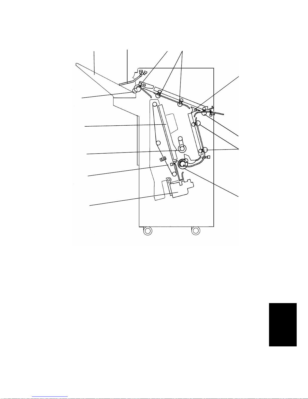
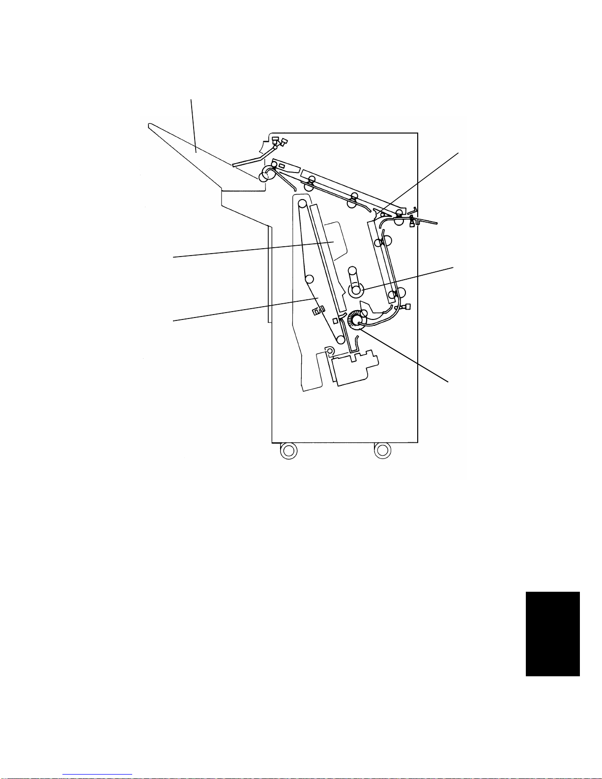
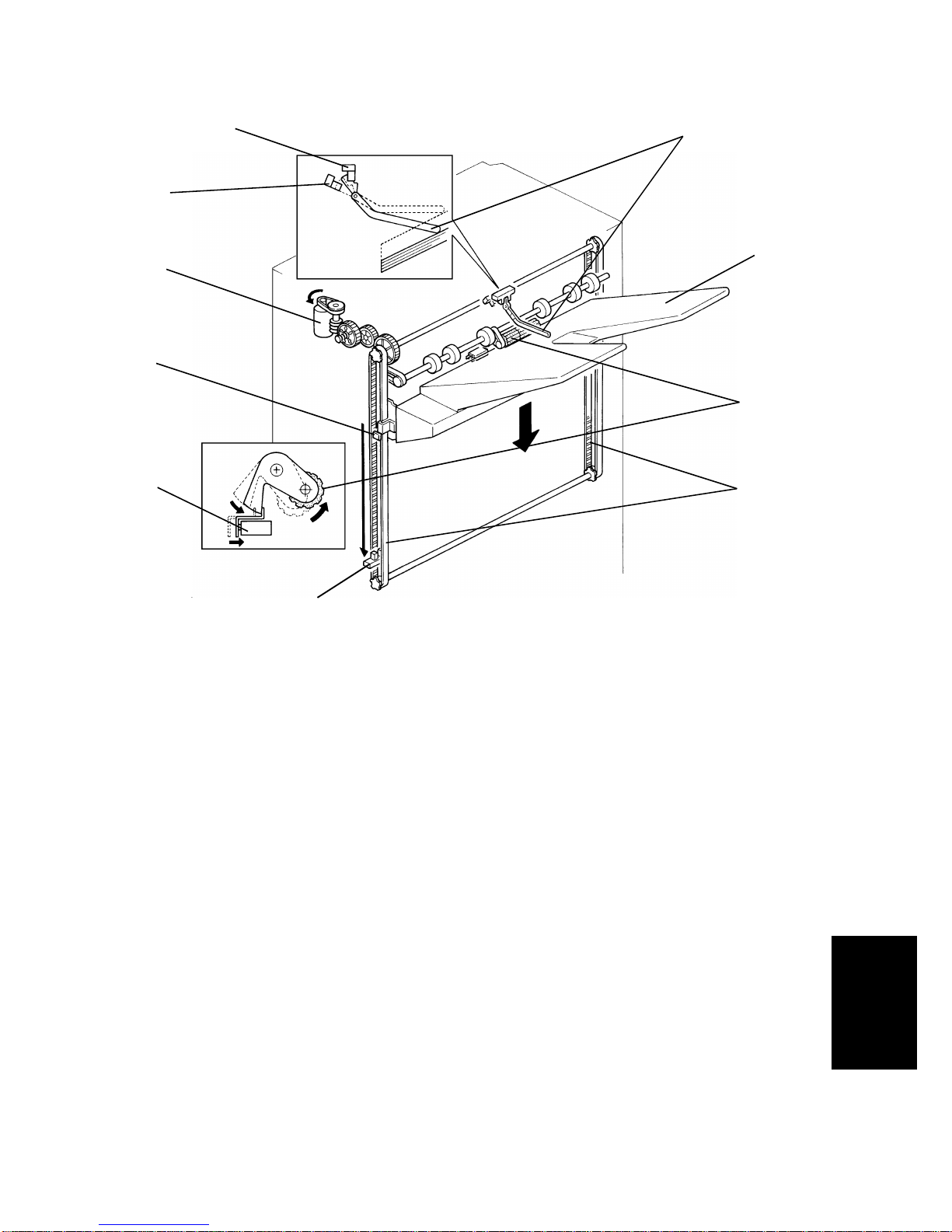
2.2 SHIFT TRAY UP/DOWN MECHANISM
The vertical position of the shift tray [A] is controlled by the shift tray lift motor
(dc motor) [B] through gears and timing belts [C]. When the main switch is
turned on, the tray position is initialized to the upper position. The tray’s
uppermost position is detected when the shift tray pushes up the actuator [D]
to deactuate the stack height sensor 1 [E].
While copying, the actuator [D] is gradually raised as the copy stack grows. In
the sort/stack mode, when stack height sensor 2 [F] remains actuated for 4
seconds, the shift tray lift motor [B] rotates, lowering the tray unit for 50 ms.
In staple mode, when the stack height sensor 1 remains deactuated for 4
seconds, the motor rotates, lowering the tray until the sensor [E] is actuated.
When the tray reaches its lower limit position, the lower limit sensor [G] is
actuated by the actuator [H], and copy operation stops.
After the copy process is finished and the machine stops, the tray is raised to
its upper most position 4 seconds after the copies are removed.
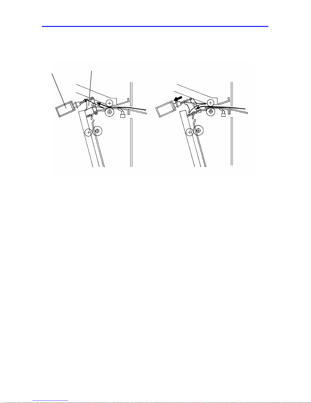
A mechanical safety switch [I] is installed to prevent the drive gears from
being damaged if the sensor does not work. When the shift tray pushes up
the shift tray positioning roller [J], the shift tray lift motor stops.
[A]
[E]
[D]
[F]
[B]
[H]
[J]
[C]
[I]
[G]
Finisher
23 April 1993 SECTIONAL DESCRIPTIONS
9

2.3 SHIFT TRAY SIDE-TO-SIDE SHIFT MECHANISM
In the sort/stack mode, the shift tray [A] moves from side to side to stagger
and separate sets of copies.
The horizontal position of the shift tray is controlled by the shift motor (dc
motor) [B] and the shift cam (helical cam) [C]. After one set of originals is
copied and delivered to the shift tray, the shift motor [B] starts rotating, driving
the shift cam through the timing belt. The pin [D] fixed to the shift tray base
plate [E] is positioned in the groove on the shift cam, creating the side-to-side
movement required to stagger copies.
When the shift cam rotates 180 degrees (when the tray is fully shifted.), the
plate [F] on the shift cam pushes the actuator [G] of the shift tray half-turn
sensor [H] and the shift motor stops. The next set of copies is then delivered.
The motor rotates repeating the same process and moving the tray back to
the previous position.
[A]
[B][C]
[D]
[E]
[F]
[G]
[H]
SECTIONAL DESCRIPTIONS 23 April 1993
10

2.4 STAPLE UNIT PAPER POSITIONING
In the staple mode, copies are vertically and horizontally aligned in the jogger
unit before being stapled.
For horizontal paper alignment, the jogger motor [A] moves both the front and
the rear jogger fences [B] to align the copies.
For vertical paper alignment, the positioning roller [C] and the alignment
brush roller [D] push the copy against the stack stopper [E].
After the trailing edge of the copy passes the jogger unit entrance sensor [F],
the positioning roller solenoid [G] is energized for 280 ms pushing the
positioning roller into contact with the paper. The positioning roller rotates to
push the paper back and align the trailing edge of the paper against the stack
stopper. Both the positioning roller and the alignment brush roller are driven
by the transport drive motor through the timing belt [H].
[F]
[E]
[C]
[D]
[A]
[B]
[G]
[H]
[F]
[C]
Finisher
23 April 1993 SECTIONAL DESCRIPTIONS
11

2.5 JOGGER MOVEMENT
When the Start key is pressed, the copier sends the paper size information to
the finisher. In accordance with that data, the jogger motor (stepper motor)
starts rotating to position the front and rear jogger fences [A] 7 mm away from
the selected paper’s edges. (1)
After the trailing edge of the copy passes the jogger unit entrance sensor,
each jogger fence moves inward 5 mm. They stop 3 mm away from the paper
edges. (2)
Just after the positioning roller pushes the copy back, each jogger fence
moves inward 2 mm more so that the leaf spring [B] on the rear jogger fence
pushes the copy side edge slightly.
After a copy is stacked in the jogger tray, the jogger fences move back 7 mm
from the copy edge for the next copy.
7 mm 2 mm
(2)(1) (3)
[A] [B]
SECTIONAL DESCRIPTIONS 23 April 1993
12

2.6 STAPLER
The staple hammer [A] is driven by the staple motor [B] via gears [C], two
eccentric cams [D], and two links [E].
When the aligned copies are brought to the staple position by the positioning
roller, alignment brush roller, and jogger fences, the stapler motor starts
rotating. When the cams complete one rotation, the stapler home position
sensor [F] turns on detecting the end of the staple operation. The stapler
motor then stops.
There is a reflecting photosensor [G] in the staple unit to detect the staple
end condition.
[E]
[C]
[B]
[A]
[F]
[D]
[G]
Finisher
23 April 1993 SECTIONAL DESCRIPTIONS
13

2.7 STAPLER UNIT SIDE-TO-SIDE MOVEMENT
Customers can select one of the following three different staple modes:
Staple 1: Top left
Staple 2: Bottom left
Staple 3: Top/Bottom left
The stapler drive motor [A] (stepper motor) moves the stapler unit [B] from
side to side. When the Start key is pressed, the stapler moves from its home
position to the staple position.
If staple mode 3 is selected, the stapler unit moves to the front staple position
first, then moves to the rear staple position. However, for the next copy set, it
staples in the reverse order; that is, at the rear side first and then at the front.
After the job is completed, the stapler unit moves back to its home position.
(The stapler unit home position sensor [C] is actuated.)
[A]
[B]
[C]
SECTIONAL DESCRIPTIONS 23 April 1993
14

2.8 FEED-OUT TO SHIFT TRAY
After being stapled, the stack feed-out motor [A] starts rotating. The pawl [B]
on the lift belt [C] transports the set of stapled copies up, and feeds it to the
shift tray. Approximately 0.6 second after the stack feed-out motor starts, the
motor stops for 400 ms. At this moment, the exit rollers catch the stapled
copies to feed them out to the shift tray. Then the motor rotates again until
the pawl actuates its home position sensor [D].
The exit drive motor starts rotating to drive the exit rollers [E] when the first
copy activates the entrance sensor. The exit drive motor speed is reduced
just before each copy paper is completely fed out. This is to ensure an even
copy stack.
[A]
[D]
[B]
[B]
[C]
[E]
Finisher
23 April 1993 SECTIONAL DESCRIPTIONS
15

3. INSTALLATION
3.1 ACCESSORY CHECK
Check the accessories in the box according to the following list.
Description Q’ty
1. Installation Procedure.............................................................1
2. Front Connecting Bracket.......................................................1
3. Rear Connecting Bracket ....................................................... 1
4. Staple Cartridge......................................................................1
5. Entrance Guide.......................................................................1
6. Shift Tray ................................................................................1
7. NECR (for -17 machine only) .................................................1
8. Cushion – 5 x 10 x 345...........................................................1
9. Cushion – 5 x 10 x 125...........................................................1
10. Cushion – 5 x 10 x 637...........................................................1
11. Philips Truss Head Screw – M4 x 8 .......................................4
12. Philips Pan Head Screw – M4 x 12........................................4
13. Philips Screw with Flat Washer – M4 x 8...............................2
14. Envelope – NECR (for -17 machine only)..............................1
INSTALLATION 23 April 1993
16

3.2 INSTALLATION PROCEDURE
CAUTION: Unplug the copier power cord before starting the following
procedure.
1. Remove the strips of tape [A] and the cushion [B].
2. Open the front door and remove the strips of tape [C] and cushions [D].
3. Remove the clamp [E] (1 screw).
4. Slide out the staple unit [F].
5. Remove the strip of tape [G].
[A]
[B]
[A]
[C]
[E]
[C]
[F] [D]
[D]
[G]
Finisher
23 April 1993 INSTALLATION
17

6. Remove five plastic caps [A] on the copier’s left cover.
7. Install the front connecting bracket [B] (2 screws– M4 x 12) and the rear
connecting bracket [C] (2 screws– M4 x 12) on the copier.
8. Stick the entrance guide mylar [D] on the copier exit area as shown.
NOTE: Align the edge [E] of the cover and the mylar.
[A]
[C] [B]
[D]
[D] [E]
INSTALLATION 23 April 1993
18

9. Secure the protective earth wire [A]* (1 screw with spring washer) and the
wire [B] (1 screw with spring washer).
*NOTE:For all models other than those intended for North America, the
green wire is meant to be used as a functional earth and should
be connected as shown.
10. Connect the fiber optics connector [C] and the 4P connector [D].
11. Open the front door of the finisher and remove the screw [E] fixing the
locking lever [F], then lower the locking lever.
12. Stick the cushions [G] (middle), [H] (short), [I] (long) as shown.
NOTE: Stick the cushion [G] on the metal stay (not on the cover).
Align the upper edge of the cushion [H] with the edge of the
stay [J].
Align the lower edge of the cushion [I] with the edge of the
stay [K].
13. Align and press the finisher against the copier and fix them by raising the
locking lever [F].
NOTE: At this time, confirm that the mylar [L] is located between the
guides [M].
14. Secure the locking lever (1 screw).
[C]
[D]
[A]
[B] [H]
[I]
[K]
[F]
[J] [G]
[E]
[M]
[M]
[L]
Finisher
23 April 1993 INSTALLATION
19
Table of contents
Other Ricoh Finisher manuals

Ricoh
Ricoh SR3300 Quick start guide

Ricoh
Ricoh SR5060 Quick start guide

Ricoh
Ricoh FS-108R User manual

Ricoh
Ricoh Rh 100 User manual

Ricoh
Ricoh SR5090 Quick start guide

Ricoh
Ricoh A763 User manual

Ricoh
Ricoh SR3020 Quick start guide

Ricoh
Ricoh DDP70 User manual

Ricoh
Ricoh SR3270 Quick start guide

Ricoh
Ricoh SR3290 Quick start guide