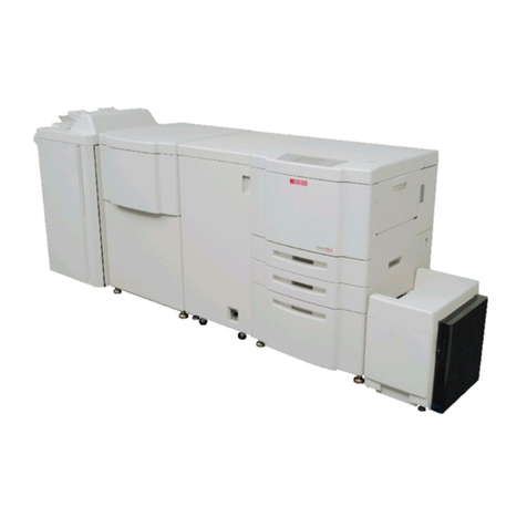
Ricoh SR4120 Quick start guide

Finisher SR4120, Booklet Finisher
SR4130
Machine Code: D3CG, D3CH
Field Service Manual
Ver 1.10
Latest Release: Jan, 2017
Initial Release: Oct, 2016
Copyright (c) 2016 - 2017 Ricoh Co.,Ltd.


Symbols, Abbreviations
This manual uses several symbols and abbreviations. The meaning of those symbols and abbreviations are as
follows:
Symbol What it means
Clip ring
Screw
Screw: Blue
Connector
Clamp
E-ring
Flat Flexible Cable
Timing Belt
Hook (sensors)
SEF Short Edge Feed
LEF Long Edge Feed
K Black
C Cyan
M Magenta
Y Yellow
B/W, BW Black and White
FC Full color
[A] Short Edge Feed (SEF)
[B] Long Edge Feed (LEF)


1
Table of Contents
1. Replacement and Adjustment.............................................................................................................................3
Covers.................................................................................................................................................................... 3
Rear Upper Cover, Rear Lower Cover, Upper Cover ....................................................................................... 3
Front Cover, Front Left Side Cover .................................................................................................................. 5
Paper Guide Cover............................................................................................................................................ 6
Paper Exit Cover ............................................................................................................................................... 8
Lower Tray...................................................................................................................................................... 11
Proof Tray ....................................................................................................................................................... 11
Upper Tray ...................................................................................................................................................... 12
End Fence (SR4130) ....................................................................................................................................... 12
End Fence (SR4120) ....................................................................................................................................... 13
Paper Guide Unit............................................................................................................................................. 14
Boards.................................................................................................................................................................. 17
Main Board...................................................................................................................................................... 17
Main Motors........................................................................................................................................................ 19
Corner Stapling Unit ....................................................................................................................................... 19
Paper Exit Gate Motor..................................................................................................................................... 24
Leading Edge Guide Motor............................................................................................................................. 24
Trailing Edge Pressure Plate Motor ................................................................................................................ 25
Stacking Roller Motor..................................................................................................................................... 25
Feed Out Motor............................................................................................................................................... 26
Jogger Motor................................................................................................................................................... 26
Paper Guide Motor.......................................................................................................................................... 27
Sensors................................................................................................................................................................. 29
Shift Tray Paper Sensor................................................................................................................................... 29
Trailing Edge Pressure Plate HP Sensor ......................................................................................................... 29
Stacking Roller HP Sensor.............................................................................................................................. 30
Staple Tray Paper Sensor ................................................................................................................................ 32
Paper Guide HP Sensor................................................................................................................................... 33
Booklet Unit Motors............................................................................................................................................ 35
Booklet Stapler Unit........................................................................................................................................ 35
Press Fold Motor............................................................................................................................................. 37
Booklet Jogger Motor...................................................................................................................................... 40
Stapler Unit.......................................................................................................................................................... 41
Stapler Unit ..................................................................................................................................................... 41
Punch Unit........................................................................................................................................................... 44
Fold Adjustments ................................................................................................................................................ 47

2
Flat Fold Roller Alignment ............................................................................................................................. 47

Adjusting the Folding Speed........................................................................................................................... 49
Flat Fold Booklet Unit Home Position Adjustment ........................................................................................ 49
Paper Guide Unit................................................................................................................................................. 52
Paper Exit Cover, Optional Output Jogger Unit.............................................................................................. 52
Paper Guide Unit............................................................................................................................................. 57
Paper Guide Unit Sensor................................................................................................................................. 60
Paper Guide Motor.......................................................................................................................................... 61
2. Detailed Descriptions.......................................................................................................................................63
Overview ............................................................................................................................................................. 63
Layout ............................................................................................................................................................. 63
Operation Details................................................................................................................................................. 71
Shift Operation (Shift Transport).................................................................................................................... 71
Pre-stack Operation (In Corner Stapling)........................................................................................................ 71
Pre-stack Operation (Booklet Stapling)........................................................................................................... 72
Upper Tray Shift Drive / Limit Sensor / Full Sensor ...................................................................................... 73
Pull-in Roller / Paper Stack Holder................................................................................................................. 75
Corner Stapling ............................................................................................................................................... 77
Saddle Stapling (Booklet Stapling)................................................................................................................. 82

1.Replacement and Adjustment
3
1. Replacement and Adjustment
Covers
Rear Upper Cover, Rear Lower Cover, Upper Cover
1. Rear upper cover [A] ( x 2)
2. Rear lower cover [A] ( x 2)

1.Replacement and Adjustment
4
3. Open the front door [A], and remove the screws of the upper cover. ( x 5)
4. Upper cover [A] ( x 2, x 2)

1.Replacement and Adjustment
5
5. Check the positions of the bosses and hooks before removing the upper cover.
6. When the upper cover is re-attached, tighten the screws on the right side in the order shown below: 1 > 2 > 3.
Front Cover, Front Left Side Cover
1. Open the front door [A], and then remove the front door bracket [B]. ( x 1)
2. Front door [A]

1.Replacement and Adjustment
6
3. Front left side cover [A] ( x 2)
Paper Guide Cover
1. Remove rear upper cover [A] ( x1).
2. Remove shift tray [A] ( x1).

1.Replacement and Adjustment
7
3. Push the guides in to the center.
4. Remove rear paper guide cover [A] ( x1).
5. Remove front paper guide cover [A] ( x2).

1.Replacement and Adjustment
8
6. Remove paper guide cover [A] screws ( x2).
7. Disconnect the front tab, and then remove the cover.
Paper Exit Cover
1. Disconnect the finisher from the main frame.
2. Remove the rear cover.

1.Replacement and Adjustment
9
3. Remove the shift tray.
4. Push the paper guides to the center.
5. Remove the rear paper guide cover.

1.Replacement and Adjustment
10
6. Remove the front paper guide cover.
7. Disconnect the main paper guide cover.
8. Carefully, separate the front tabs at [A], and then remove the main paper guide cover [B].

1.Replacement and Adjustment
11
Lower Tray
1. Lower tray [A]
Proof Tray
1. Remove the following covers. Rear Upper Cover, Rear Lower Cover, Upper Cover
•Rear upper cover
•Upper cover
2. Proof tray [A] ( x 2)

1.Replacement and Adjustment
12
Upper Tray
1. Upper tray [A] ( x 1)
End Fence (SR4130)
1. Remove the rear upper cover. Rear Upper Cover, Rear Lower Cover, Upper Cover
2. Support the upper tray [A] with your right hand, and then pull gear [B] toward you to release.
3. Upper tray [A] ( x 1)
4. Lower Tray (Lower Tray)

1.Replacement and Adjustment
13
5. End fence [A] ( x 2)
End Fence (SR4120)
1. Upper Tray [A] ( x 1)
2. Shift tray bracket [A] ( x 4)

1.Replacement and Adjustment
14
3. End fence [A] ( x 3)
Paper Guide Unit
1. Remove the paper exit guide.
2. If the Output Jogger Unit Type M25 (option) unit is installed, remove it.
3. Remove paper guide cover support bracket [A] ( x2).
4. At the front and back remove the shoulder screws [A] and [B] of the output jogger unit if it was installed.
•Removing the jogger unit makes it easier to access the paper guide unit fastening screws. Do not
lose these screws.

1.Replacement and Adjustment
15
5. Loosen the proof tray screws temporarily to make it easier to reach the paper guide fastening screws.
6. Remove the paper guide fastening screws at the front [A] and rear [B] ( x4).

1.Replacement and Adjustment
16
7. At the rear, open the clamp, and then disconnect the motor and sensor ( x2, x2).
8. Tilt the paper guide unit toward you, and then disconnect the harness of motor bracket [A].
9. Remove the paper guide unit and place on a flat, clean surface.
This manual suits for next models
1
Table of contents
Other Ricoh Finisher manuals

Ricoh
Ricoh SR400 User manual

Ricoh
Ricoh SR3290 Quick start guide

Ricoh
Ricoh DDP 92 User manual

Ricoh
Ricoh SR3300 Quick start guide

Ricoh
Ricoh FS-108R User manual

Ricoh
Ricoh SR4110 Quick start guide

Ricoh
Ricoh SR5090 Quick start guide

Ricoh
Ricoh SR3270 Quick start guide

Ricoh
Ricoh DDP70 User manual

Ricoh
Ricoh SR3020 Quick start guide