Ridge Tool Company 3
•Remove adjusting keys or switches before turning
the tool ON. A wrench or a key that is left attached to
a rotating part of the tool may result in personal injury.
•Do not overreach. Keep proper footing and bal-
ance at all times. Proper footing and balance en-
ables better control of the tool in unexpected situations.
•Use safety equipment. Always wear eye protec-
tion. Dust mask, non-skid safety shoes, hard hat, or
hearing protection must be used for appropriate con-
ditions.
Some dust created by power sanding,
sawing, grinding, drilling and other construction activi-
ties contains chemicals known to the State of California to
cause cancer, birth defects, or other reproductive harm.
Some examples of these chemicals are:
• lead from lead-based paints
• crystalline silica from bricks and cement and other
masonry products
• arsenic and chromium from chemically-treated lum-
ber
Your risk from these exposures varies, depending on
how often you do this type of work. To reduce your ex-
posure to these chemicals: work in a well ventilated area,
and work with approved safety equipment, such as those
dust masks that are specially designed to filter out mi-
croscopic particles.
•Wear hearing protectors, ear plugs or muffs when
using tool. Noise level my affect hearing with pro-
longed use.
Tool Use and Care
•Use clamp or other practical way to secure and
support the workpiece to a stable platform. Holding
the work by hand or against your body is unstable and
may lead to loss of control.
•Do not force tool. Use the correct tool for your ap-
plication. The correct tool will do the job better and
safer at the rate for which it is designed.
•Do not use tool if switch does not turn it ON or
OFF. Any tool that cannot be controlled with the switch
is dangerous and must be repaired.
•Disconnect the plug from the power source before
making any adjustments, changing accessories,
or storing the tool. Such preventive safety mea-
sures reduce the risk of starting the tool accidentally.
•Store idle tools out of the reach of children and
other untrained persons. Tools are dangerous in
the hands of untrained users.
•Maintain tools with care. Keep cutting tools sharp
and clean. Properly maintained tools with sharp cutting
edges are less likely to bind and are easier to control.
•Check for misalignment or binding of moving
parts, breakage of parts, and any other condition
that may affect the tool's operation. If damaged,
have the tool serviced before using. Many accidents
are caused by poorly maintained tools.
•Use only accessories that are recommended by
the manufacturer for your model. Accessories that
may be suitable for one tool may become hazardous
when used on another tool.
•Keep handles dry and clean; free from oil and
grease. Allows for better control of the tool.
Service
•Tool service must be performed only by qualified
repair personnel. Service or maintenance performed
by unqualified repair personnel could result in injury.
•When servicing a tool, use only identical replace-
ment parts. Follow instructions in the Maintenance
Section of this manual. Use of unauthorized parts or
failure to follow maintenance instructions may create a
risk of electrical shock or injury.
Specific Safety Information
WARNING! Read and follow safety labels on the tool!
Know the location and function of all con-
trols before using this hole cutting tool.
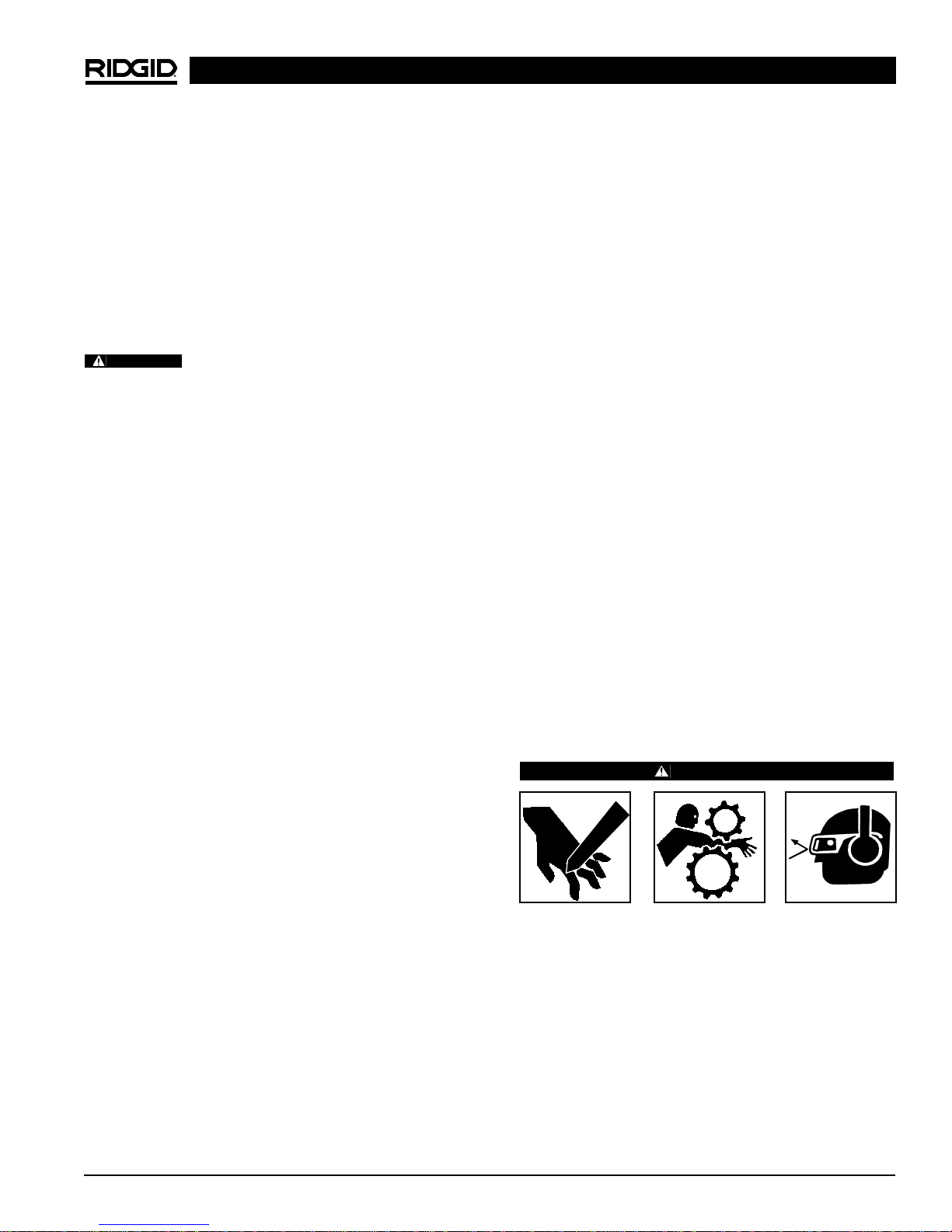
WARNING
Clothing/gloves can be caught in moving parts.
Fingers, hands, arms or other body parts can be cut,
crushed or broken.
• Keep fingers and hands away from cutter blade.
• Do not reach across cutter or pipe because
clothing can be drawn into moving parts.
• Do not disconnect or block switch.
• Keep switch in working order.
• When cutting into existing system, pipe must
be drained and de-pressurized.
• Wear safety glasses and ear protection.
• Test Ground Fault Circuit Interrupter (GFCI) to
insure proper operation.
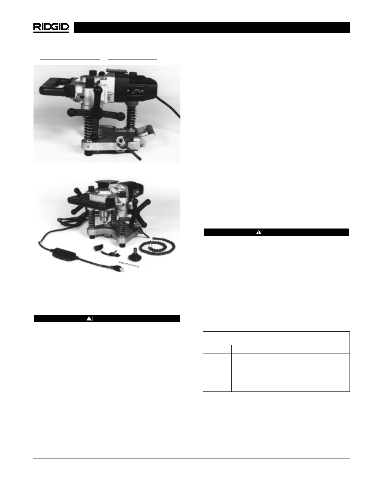
HC-450/HC-300 Hole Cutting Tools
WARNING