EnglishDeutsch
 logo
Brands
  1. Home
  2. •
  3. Brands
  4. •
  5. RIDGID
  6. •
  7. Power Tools
  8. •
  9. RIDGID 975 Combo User manual

RIDGID 975 Combo User manual

Other RIDGID Power Tools manuals

RIDGID R9213 User manual

RIDGID

RIDGID R9213 User manual

RIDGID JobMax R2851 User manual

RIDGID

RIDGID JobMax R2851 User manual

RIDGID 1224 User manual

RIDGID

RIDGID 1224 User manual

RIDGID Compact 100-B User manual

RIDGID

RIDGID Compact 100-B User manual

RIDGID RP 210 User manual

RIDGID

RIDGID RP 210 User manual

RIDGID Pipe Vise User manual

RIDGID

RIDGID Pipe Vise User manual

RIDGID R3120 User manual

RIDGID

RIDGID R3120 User manual

RIDGID RP 240 User manual

RIDGID

RIDGID RP 240 User manual

RIDGID RP 240 User manual

RIDGID

RIDGID RP 240 User manual

RIDGID 700 User manual

RIDGID

RIDGID 700 User manual

RIDGID R860435 User manual

RIDGID

RIDGID R860435 User manual

RIDGID End Pipe Wrench User manual

RIDGID

RIDGID End Pipe Wrench User manual

RIDGID 918 User manual

RIDGID

RIDGID 918 User manual

RIDGID R138HPA User manual

RIDGID

RIDGID R138HPA User manual

RIDGID R883 User manual

RIDGID

RIDGID R883 User manual

RIDGID R84044 User manual

RIDGID

RIDGID R84044 User manual

RIDGID HC-2D User manual

RIDGID

RIDGID HC-2D User manual

RIDGID R150FSF User manual

RIDGID

RIDGID R150FSF User manual

RIDGID JobMax R8223411 User manual

RIDGID

RIDGID JobMax R8223411 User manual

RIDGID DP1500 User manual

RIDGID

RIDGID DP1500 User manual

RIDGID R1500 User manual

RIDGID

RIDGID R1500 User manual

RIDGID 600-I User manual

RIDGID

RIDGID 600-I User manual

RIDGID 600 User manual

RIDGID

RIDGID 600 User manual

RIDGID OCTANE JobMax E Series User manual

RIDGID

RIDGID OCTANE JobMax E Series User manual

Popular Power Tools manuals by other brands

AEG OMNI-JS Original instructions

AEG

AEG OMNI-JS Original instructions

SIP 01533 manual

SIP

SIP 01533 manual

Ribimex PRS499 quick start guide

Ribimex

Ribimex PRS499 quick start guide

3M Fiber Optic Connector Crimp Tool instructions

3M

3M Fiber Optic Connector Crimp Tool instructions

Ryobi P524 Operator's manual

Ryobi

Ryobi P524 Operator's manual

ROJEK FSN 300A manual

ROJEK

ROJEK FSN 300A manual

WABCO OptiTire installation manual

WABCO

WABCO OptiTire installation manual

EINHELL TE-MS 18/210 Li Original operating instructions

EINHELL

EINHELL TE-MS 18/210 Li Original operating instructions

Orgapack OR-T 85 Operating and safety instructions

Orgapack

Orgapack OR-T 85 Operating and safety instructions

TOUGHCUT Diamond 400 instruction manual

TOUGHCUT

TOUGHCUT Diamond 400 instruction manual

Yaros PB-3603 user manual

Yaros

Yaros PB-3603 user manual

Fein BSS 2.0 E Repair instructions

Fein

Fein BSS 2.0 E Repair instructions

Baileigh Industrial SS-2725 Operator's manual

Baileigh Industrial

Baileigh Industrial SS-2725 Operator's manual

Milwaukee 2674-20 Operator's manual

Milwaukee

Milwaukee 2674-20 Operator's manual

Fein BLs 1.6 parts list

Fein

Fein BLs 1.6 parts list

Princess Electric Multi Sharpener user manual

Princess

Princess Electric Multi Sharpener user manual

FOREDOM K.1050 Operation & maintenance manual

FOREDOM

FOREDOM K.1050 Operation & maintenance manual

Silca MARKER 2000 operating manual

Silca

Silca MARKER 2000 operating manual

https://manuals.online logo
https://manuals.online logoBrands
  • About & Mission
  • Contact us
  • Privacy Policy
  • Terms and Conditions

Copyright 2026 Manuals.Online. All Rights Reserved.

975 Combo Roll Groover
Groove and Drive Roll Set Change-out Instructions
Kit Includes:
• 32838 Driveshaft for 2" - 8" Copper
• 30893 Driveshaft Key
• 32843 Groove Roll for 2" - 8" Copper
WARNING
Read and understand the threading machine and roll groover
operator’s manuals and instructions for all other equipment
being used before operating. Failure to follow all instruc-
tions may result in property damage and/or serious personal
injury.
Make sure the machine FOR/OFF/REV switch is in the OFF
position and the machine is unplugged before performing any
maintenance or making any adjustments.
SAVE THESE INSTRUCTIONS!
Contact Ridge Tool Technical Service Department at (800)
519-3456 or [email protected] if you have any
questions.
Changing Roll Sets
When changing roll set parts, always make
sure drive and groove roll markings match. Mismatched
parts can make improper grooves and cause leaks.
Remove the roll groover from the power drive or threading
machine and place on a stable work bench.
Required Tools:
•3/8" Hex Wrench
•3/32" Hex Wrench
• .070" External Retaining Ring Pliers
Removing and Installing Drive Roll
1. Remove 6 screws that hold rear cover to the housing.
2. Remove the rear cover
(See Figure 1)
.
Figure 1 – Removing Rear Cover
3. Remove pinion.
4. Remove the driveshaft assembly out of the back of the
975 Roll Groover.
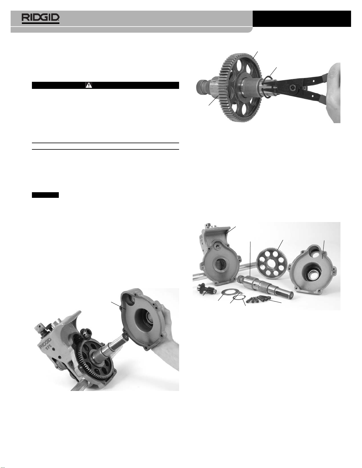
5. Remove retaining ring from driveshaft and slide gear off.
(See Figure 2.)
Figure 2 – Removing Retaining Ring
6. Remove key and then thrust washer.
7. Slide thrust washer onto new driveshaft.
8. Insert key and install gear.
9. Install retaining ring into driveshaft groove.
10. Place driveshaft assembly into main housing.
11.Grease from the gearbox may have been lost during
the driveshaft change. Make sure the bearings and
gear teeth are coated sufficiently with a good general
purpose grease.
12. Insert pinion and reinstall rear cover. Tighten screws to
12-16 ft*lbs of torque.
Figure 3 – 975 Combo Roll Groover Parts Diagram
Removing and Installing Groove Roll
1. Remove the setscrew that holds the groove roll shaft in
place.
2. Pull the groove roll shaft out of the slide block and
remove the groove roll and thrust washer.
3. Insert the thrust washer and new groove roll into the
slide block. Ensure that the internal retaining ring in
the groove roll is closest to the main housing, and that
the groove roll is between the thrust washer and main
housing.
(See Figure 4.)
4. Replace the groove roll shaft and the set screw.
5. Visually inspect the alignment between the groove roll
and the drive roll. If they are not aligned, check orienta-
tion of groove roll and thrust washer.
058-005-726.10
NOTICE
Gear
Thrust
Washer
Retaining Ring
Main Housing
Pinion
Driveshaft Rear Cover
Gear
Screws
Retaining Ring
Thrust
Washer Key
Rear Cover
Test Equipment Depot - 800.517.8431
99 Washington Street, Melrose, MA 02176
TestEquipmentDepot.comTe
RidgeTool Company/Elyria, Ohio, U.S.A.
2
975 Combo Roll Groover
Groove and Drive Roll Set Change-out Instructions
Figure 4
6. Grease as directed in
Lubrication Section
of manual.
Setting The Groove Diameter For Copper
Tubing
When using the 975 Combo Roll Groover for copper tube,
the groove depth gauge on the groover cannot be used. It
will give incorrect groove diameters.
1. Turn the feedscrew clockwise to bring the groove roll
down in contact with the pipe outside diameter, then turn
the feedscrew one quarter additional turn. The adjust-
ing screw may need to be loosened (turned counter-
clockwise) to allow the groove roll to contact pipe. The
pipe and roll groover should be secure to each other at
this point.
2. Make sure the groove depth
gauge is in the grooving po-
sition.
(Figure 5)
3. Turn the adjusting screw until it
is flush with the top plate of
the groover.
4. Find the diameter and type of
pipe to be grooved on Table A
and back the adjusting screw
off the top plate the corre-
sponding number of turns. For example, for 4" Sch. L
copper, back the adjustment screw 11/4turns.
5.
Go to step 4 of “Setting/Measuring The Groove Dia-
meter” in the 975 Combo Groover operator’s manual.In
step 6 use the Copper Roll Groove Specifications.
Service and Repair
WARNING
Improper service or repair can make machine unsafe
to operate.
Tool should be taken to a RIDGID Independent Authorized
Service Center or returned to the factory.
When servicing this machine, only identical replacement
parts should be used. Use of other parts may create a risk
of serious injury.
Chart A – Depth Adjustment for Roll Grooving Copper
Tubing
Depth Adjustment for Roll Grooving CopperTubing
(Adjusting ScrewTurns)
Dia. K L M DWV
2-2.5" 7/87/85/85/8
3" 11/16 11/16 11/16 11/16
4" 11/411/411/411/8
5" 11/211/211/211/2
6" 113/16 13/413/413/4
8" 21/223/821/821/8
Figure 5 – Gauge In
Grooving Position
Table I. Copper Roll Groove Specifications
1 2 345678
AB CDT
Nom. Tubing Outside Gasket Groove Groove Groove Min. Max.
Size Diameter O.D. Seat Width Dia. Depth Allow. Allow.
Inches A +.03 +.00 Ref.1Wall Flare
Basic Tolerance ±0.03 –.000 –.02 Thick. Dia.
2" 2.125 ±0.002 0.610 0.300 2.029 0.048 DWV 2.220
21/2" 2.625 ±0.002 0.610 0.300 2.525 0.050 0.065 2.720
3" 3.125 ±0.002 0.610 0.300 3.025 0.050 DWV 3.220
4" 4.125 ±0.002 0.610 0.300 4.019 0.053 DWV 4.220
5" 5.125 ±0.002 0.610 0.300 5.019 0.053 DWV 5.220
6" 6.125 ±0.002 0.610 0.300 5.999 0.063 DWV 6.220
8" 8.125 +0.002/-0.004 0.610 0.300 7.959 0.083 DWV 8.220
1. Nominal Groove Depth is provided as a reference dimension. Do not use groove depth to determine groove acceptability.
Main Housing
Set Screw
Thrust
Washer
Groove
Roll
Slide
Block
99 Washington Street
Melrose, MA 02176
Phone 781-665-1400
Toll Free 1-800-517-8431
Visit us at www.TestEquipmentDepot.com