manuals.online logo
Brands
  1. Home
  2. •
  3. Brands
  4. •
  5. Rielta
  6. •
  7. Security Sensor
  8. •
  9. Rielta STEKLO-2 User manual

Rielta STEKLO-2 User manual

General Information
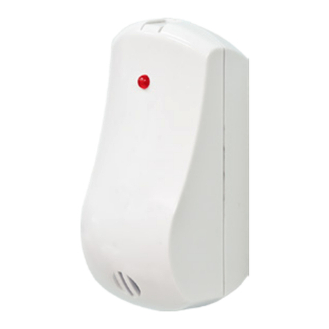
Glass break detector «Steklo-2»(hereinafter, the Detector) is intended
for detecting destruction of the following types of flat glass:
- customary glass with a thickness 2.5 … 8 mm;
- patterned glass with thickness 3.5 … 7 mm;
- laminated glass with polymer film,
having area not less than 0.1 m2(with length of any side not less than
0.3 m), as well as hollow glass blocks with the following alarm message
transmission to the control panel. The Detector comprises LED indicator
for the Detector state displaying.
The Detector is supplied by the CP via alarm loop (hereinafter, AL)
with input voltage range 10 … 30 V DC.
Operating temperature: from minus 20 to 45 0С.
Ambient class: Boreal Climate.
The Detector is designed for continuous operation around a clock.
Principal Technical Characteristics
Maximum detection range of the Detector under the impact on the
protected glass, inserted into a framework – not less than 6 m.
The Detector operates at two frequencies.
The Detector provides it’s sensitivity adjustment.
Warm-up time – not more than 30 sec.
Consumption current in standby mode (during «Norm»message
generation) is not more than 1 mA at AL voltage 10 … 30 V DС.
The Detector informative capacity:
a) «Norm» message;
b) «Alarm» message.
«Norm»message is generated during all security period of the Detector
operation in absence of destroying impacts on the protected glass by
creation current in AL with the rate, corresponding to consumption current
in standby mode. «Norm» state is displayed by LED lighting absence.
The Detector generates an «Alarm»message after registration of
destroying impacts on the protected glass by increasing current in AL,
whereupon supply voltage rate decreases till the level not more than
5.2 V. Upon that, the current rate in the Detector should not exceed
35 mA. LED indicator should light steadily.
ATTENTION! It is allowed to hook the Detector only in circuits with
current limiting till the level not exceeding 35 mA. Connection of the
Detector to power source without limiting resistor (1 kΩ) is absolutely
forbidden.
Detection of the glass sheet destruction probability is not less than 0.9.
The Detector provides IP rating IP30.
Dimensions, not more than 80 х 80 х 35 mm.
Weight of the Detector is not more than 0.1 kg.
Mean time to failure in «Norm» mode – not less than 60 000 hours.
The Detector average life – not less than 8 years.
Scope of Delivery
Each Detector unit package contains the items listed in Table 1.
Table 1
Name QNT
Glass break detector «Steklo-2»
Assessories set:
Testing ball
Mounting set:
Screw 1-3х20.016
Glass break detector «Steklo-2». Installation Guide
1 pc.
1 pc.*
2 pcs.
1 copy
* – Single for 26 detectors
Installation
Examples of the Detector installation are shown in Figures 5 – 10,
fixation marking – in Figure 1.
When choosing place of the Detector installation at the secured object,
it is necessary to take into account the following requirements:
- possibility of the Detector installation on any of side walls
(Figure 6) or opposite wall (Figure 7), on the room ceiling (Figures 5
and 8), as well as on partition between secured glass and curtains
(Figure 9);
- the Detector detection zone orientation (Figure 3);
- it is allowed to use the Detector simultaneoully with active ultrasonic
detectors;
- all segments of the secured glass should be within the visibility
range of the Detector;
- masking of the Detector by curtains is forbidden, as it leads to the
Detector sensitivity loss;
GLASS BREAK
DETECTOR
«STEKLO-2»
Figure 1
Installation Guide
Figure 2
Top view Side view
Figure 3 – GB detection zone pattern
Microphone
orientation
Microphone
orientation
Steel ball
ø21 ... 22 mm
Inclination
angle
30 ... 700
35 cm
Glass
R 6m
900
R 6m
+Input- +Output-
CP
To the CP
terminal element
(56 ± 0.5) mm
2 fixation holes (for 3 mm screw)
Figure 4
Adjustment
The Detector adjustment is fulfilled as follows:
- open the Detector cover;
- set DIP-switches 1, 2 and 3 in ON position;
- suspend a steel ball 21 – 22 mm in diameter on a 35 cm long
thread near the farthest part of the monitored glass, as it is shown in
Figure 4. Deliver indestructible blow to the most distant place of the
secured glass. Recommended deflection angles are listed in Table 2,
for hollow glass blocks the inclination angle is 45°;
Table 2
Glass Thickness, mm <3 3...4 4...5 5...6 6...7 >8
Ball deflection angle for ordinary
and patterned glass, 030 35 40 45 50 55
Ball deflection angle for
laminated glass, 045 50 55 60 65 70
- if LED indicator is not lighting after test blows, the Detector sensitivity
should be increased by DIP-switches «1» and «2» (See Table 3);
Table 3
DIP-switch Position Detector Mode of Operation
1 2 3
ON
OFF
ON
OFF
ON
ON
OFF
OFF
ON
ON
ON
ON
Sensitivity (detection
range)
minimum
+6 dB
+14 dB
+20 dB (maximum)
ON
OFF
Adjustment
Standby mode
- distance between the Detector and farest point of the secured
surface should not exceed 6 m.
Connection
Connection diagramm is shown in Figure 2.
1200
Rev.1 of 10.04.14
№
00056
Made in Russia
«RIELTA» JSC, www.rielta.com
Chapaeva Str. 17, Saint Petersburg, Russia, 197101, [email protected]
Tel./fax: +7 (812) 233-0302, 703-1360,
Technical support, tel. +7 (812) 233-29-53, 703-13-57, [email protected]
Packing Certificate
Glass break detector «Steklo-2» has been manufactured in compliance with the active technical documentation, classified as fit for operation
and packed by «RIELTA» JSC.
Packing date _______________________________
month, year
Detector
Detector
not less than 2 m
not more than 6 m
not more than 6 m
Figure 5 – Ceiling mounting of the Detector Figure 7 – Opposite wall mounting
of the Detector
Figure 6 – Side wall mouning of the Detector
Detectors
Detector
not more than 6 m more than 6 m
less than 2 m
less than 2 m
Figure 9 –The Detector mounting between
glass and curtains (louvre-boards)
Figure 10 – Not recommended installation
places
Detector
not more than 6 m
not less than 2 m
Figure 8 – Ceiling mounting of the Detector
(for window openings in neibour walls
monitoring)
Detector
not more than 6 m
- select the sensitivity level, at which the Detector responds (Alarm message is generated) after testing ball blows the glass;
- close the Detector cover and fulfill analogous testing with other secured glasses in different places, if it is neccessary adjust sensitivity;
- check the Detector adjustment by delivering a blow by testing ball to the glass with the inclination angle 15 – 25°. Upon that, the Detector
should not generate an alarm message. If the test is unsuccessful, repeat the Detector adjustment procedure.
Note – For the Detector operation check, it is allowed to use electronic glass break simulator during adjustment.
To finish preparation of the Detector to operation on the secured object, set the DIP-switch 3 to «standby mode»position, close the cover, seal
it if necessary.
The Detector warranty period is 5 years as from the date of production.
Variants of the Detector Installation
Correct installation variants are shown in Figures 5 – 9, wrong ones – in Figure 10.

Other Rielta Security Sensor manuals

Rielta Ladoga MK-RK version 2 User manual

Rielta

Rielta Ladoga MK-RK version 2 User manual

Rielta ZVON-1 User manual

Rielta

Rielta ZVON-1 User manual

Rielta Ladoga MK-RK User manual

Rielta

Rielta Ladoga MK-RK User manual

Rielta PYRONE-SH2-RK User manual

Rielta

Rielta PYRONE-SH2-RK User manual

Rielta Ladoga IPR-RK User manual

Rielta

Rielta Ladoga IPR-RK User manual

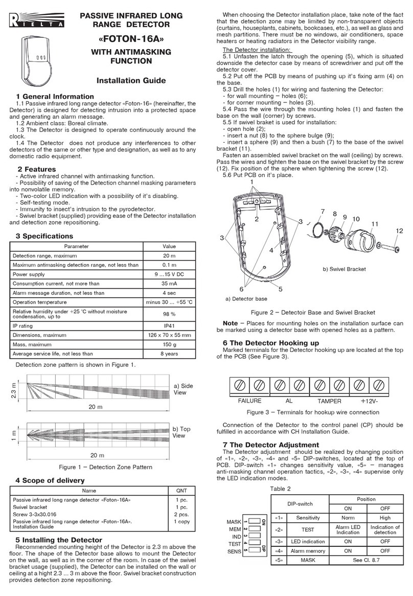
Rielta FOTON-16B User manual

Rielta

Rielta FOTON-16B User manual

Rielta IPDL-Ex User manual

Rielta

Rielta IPDL-Ex User manual

Rielta FOTON-15A User manual

Rielta

Rielta FOTON-15A User manual

Rielta FOTON-12-RK User manual

Rielta

Rielta FOTON-12-RK User manual

Rielta STEKLO-3M User manual

Rielta

Rielta STEKLO-3M User manual

Rielta Pyrone-4RK User manual

Rielta

Rielta Pyrone-4RK User manual

Rielta Ochrana FOTON-19RK User manual

Rielta

Rielta Ochrana FOTON-19RK User manual

Rielta STZ-RK User manual

Rielta

Rielta STZ-RK User manual

Rielta chrana ORLAN-SH User manual

Rielta

Rielta chrana ORLAN-SH User manual

Rielta FOTON-SH2-RK User manual

Rielta

Rielta FOTON-SH2-RK User manual

Rielta ZVON-1 User manual

Rielta

Rielta ZVON-1 User manual

Rielta FOTON-10MD User manual

Rielta

Rielta FOTON-10MD User manual

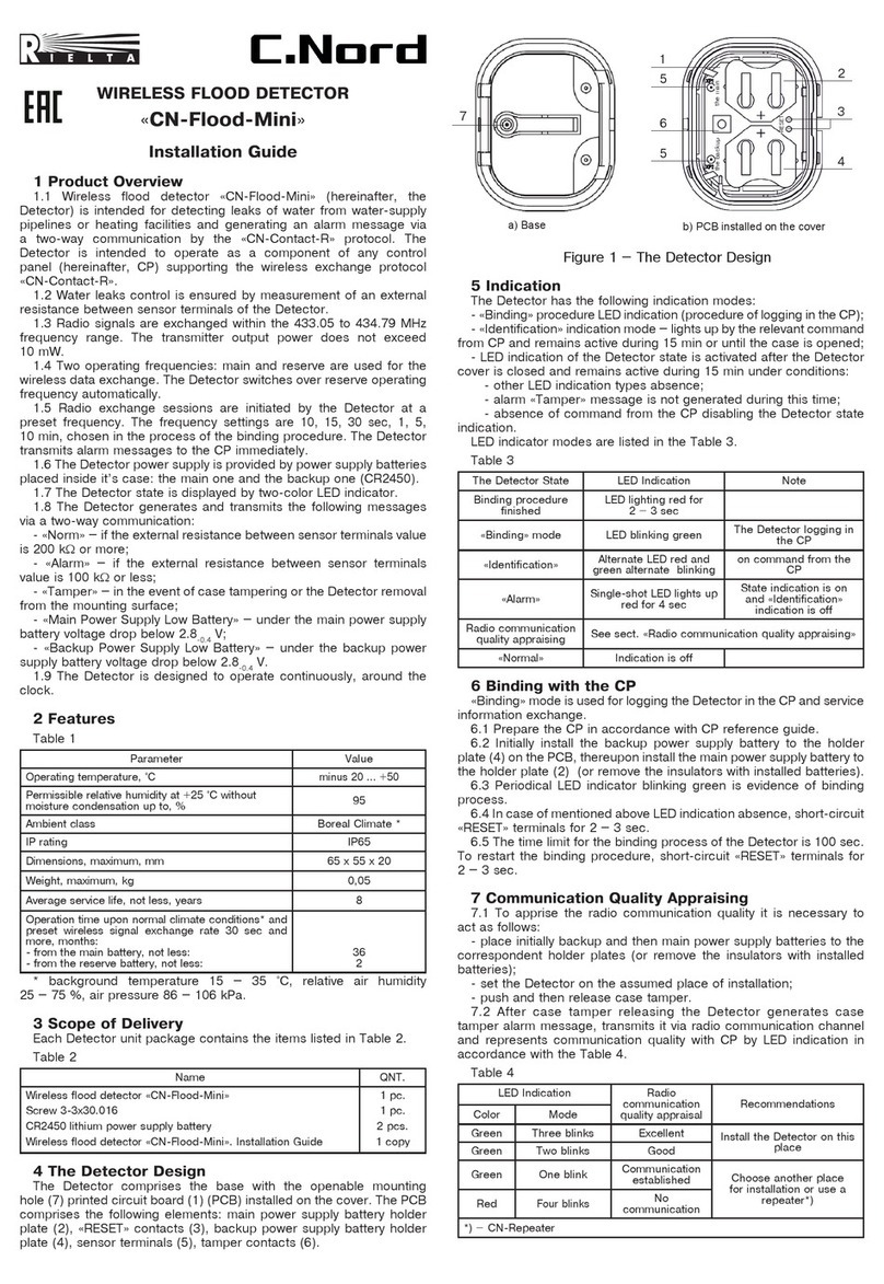
Rielta C.Nord CN-Glass User manual

Rielta

Rielta C.Nord CN-Glass User manual

Rielta ORLAN-2 User manual

Rielta

Rielta ORLAN-2 User manual

Rielta Ladoga MK-RK User manual

Rielta

Rielta Ladoga MK-RK User manual

Rielta UDAR User manual

Rielta

Rielta UDAR User manual

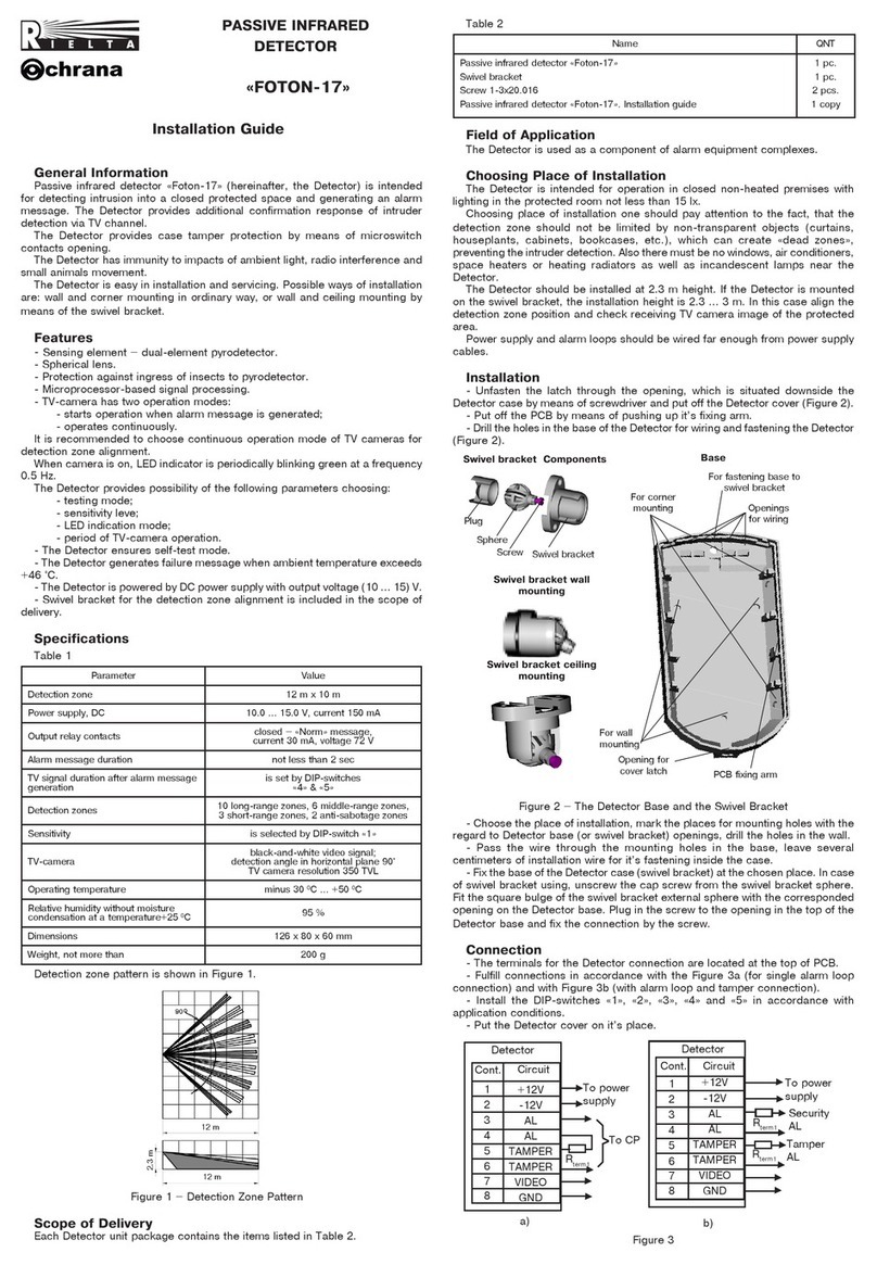
Rielta FOTON-17 User manual

Rielta

Rielta FOTON-17 User manual

Rielta STEKLO-3RK User manual

Rielta

Rielta STEKLO-3RK User manual

Rielta FOTON-21 User manual

Rielta

Rielta FOTON-21 User manual

Popular Security Sensor manuals by other brands

Data Harvest 1207 manual

Data Harvest

Data Harvest 1207 manual

Dors 115 user manual

Dors

Dors 115 user manual

AVIRE E-MOTIVE EPS installation guide

AVIRE

AVIRE E-MOTIVE EPS installation guide

Beko METPOINT CID quick start guide

Beko

Beko METPOINT CID quick start guide

Johnson Controls RLD-H10G manual

Johnson Controls

Johnson Controls RLD-H10G manual

SBS SBS-H2 Installation, operating,  & maintenance instructions

SBS

SBS SBS-H2 Installation, operating, & maintenance instructions

Petzl FALCON MOUNTAIN C385030E Instructions for use

Petzl

Petzl FALCON MOUNTAIN C385030E Instructions for use

Varian 956 Installation, operation and maintenance instructions

Varian

Varian 956 Installation, operation and maintenance instructions

Gira 0335 00 installation instructions

Gira

Gira 0335 00 installation instructions

Berker 2996 user manual

Berker

Berker 2996 user manual

CMC Rescue MPD user manual

CMC Rescue

CMC Rescue MPD user manual

Cooper PPAD-C-HB-230V Product guide

Cooper

Cooper PPAD-C-HB-230V Product guide

ATS BULLSEYE user manual

ATS

ATS BULLSEYE user manual

EVERSPRING SP103 manual

EVERSPRING

EVERSPRING SP103 manual

Det-Tronics X3302 instructions

Det-Tronics

Det-Tronics X3302 instructions

Dräger GS3 Instructions for use

Dräger

Dräger GS3 Instructions for use

DSC WLS912 GUIDELINES AND INSTALLATION INSTRUCTIONS

DSC

DSC WLS912 GUIDELINES AND INSTALLATION INSTRUCTIONS

Ecolink WST-702 installation instructions

Ecolink

Ecolink WST-702 installation instructions

manuals.online logo
manuals.online logoBrands
  • About & Mission
  • Contact us
  • Privacy Policy
  • Terms and Conditions

Copyright 2025 Manuals.Online. All Rights Reserved.