manuals.online logo
Brands
  1. Home
  2. •
  3. Brands
  4. •
  5. Risco
  6. •
  7. Security Sensor
  8. •
  9. Risco LuNAR PR RK2000DPC User manual

Risco LuNAR PR RK2000DPC User manual

The lens in LuNAR PR provides detection sectors (beams) arranged in three
all-round optical levels, the external including 12 sectors, the middle
12 sectors and the internal 6 sectors. This arrangement assures you the best
coverage of the area. See plan view, fig. 4.
The unit should not be mounted in direct sunlight or any other direct light or any
heat source (i.e. above a stove, radiator etc.). Detection sectors should
be pointing towards the floor, not curtains, windows etc.
Hold the unit with its base in the palm of your hand
and turn the cover clockwise to open, as
illustrated in Fig. 2.
The turning movement will release the 4 latches
locking the cover to the base of the unit.
The unit includes knockouts for mounting and wiring. Open the appropriate
knockouts required the installation.
Insert the cable through the hole you
opened and mount the bottom part
in its final location.
Seal the cable hole and any other
opening with a sealant (RTV or alike).
The following wire connection should be made to the terminal strip located
at the right lower part of the PC board.
SPECIFICATIONS
ELECTRICAL: PHYSICAL:
Detection technology: Dual element PIR Weight: 112 G (4 Oz)
Current consumption: 15 mA at 12 VDC Size: Ø135 x 27 mm
Supply voltage: 9-16 VDC regulated
Alarm contact: 24 VDC, 50 mA
Anti-tamper: Normaly closed, 24 VDC,0.5 A
Pulse count: Selectable 1-3
Temperature compensation: True Temp. compensation
RF immunity: According to EN50130-4
Walk test: 1 LED
OPTICAL: ENVIROMMENTAL:
Lens: Wide angle spherical Fresnel Operating 0ºC to 55ºC
Coverage: 110º angle, 360º overview temperature: (32ºF to 131ºF)
Detection Zones: 3 optical levels, 12 external sectors, Storage -20ºC to 60ºC
12 middle sectors, 6 internal sectors temperature: (-4ºF to 140ºF)
TERMINAL DESCRIPTION
(-) (+) 12 VDC DC Voltage (9 to 16 VDC).
N.C. Normally closed alarm contacts.
TAMPER Anti-tamper circuit.
NOTE: Ensure that cover is installed after mounting and wiring.
Do not check or test detector without cover closed.
OPTICAL FEATURES
The following is a description of features of RISCO GROUP's Fresnel lens fitted
in LuNAR PR.
Set the "PULSES" to "1" and "LED" to "ON" (JP1).
With the LuNAR PR closed and powered in the setting, the LED will light each
time detection occurs, so operation can be checked.
After walk testing, the LED setting may be SET to "OFF". Now the detector will
work normally, but the LED will not light when detection occurs and the intruder
will notice being detected.
© RISCO Group 11/2020 5IN1805 D
LuNARTM PR
360º CEILING MOUNT
DIGITAL PIR DETECTOR
GENERAL DESCRIPTION
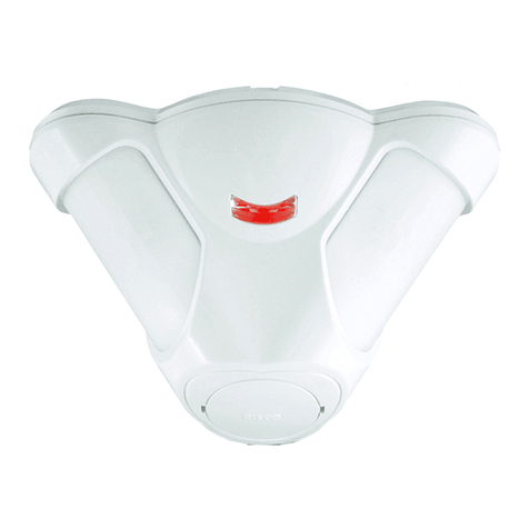
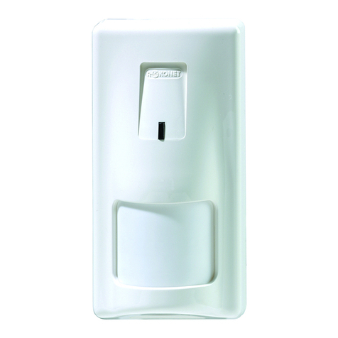
The LuNAR PR 360º ceiling mount digital PIR is designed with state-of-the-art
components to ensure reliable operation in a wide range of applications.
It has a wide 110º angle, 360º overview. LuNAR PR uses a dual element
pyroelectric technology and provides superior RFI/EMI protection.
In addition, the LuNAR PR has digital true temperature compensation.
TERMINALS
MOUNTING
KNOCKOUT
CABLE
KNOCKOUT
CABLE
KNOCKOUT
MOUNTING
KNOCKOUT
PYROELECTRIC
ELEMENT
EOL Resistors
ANTI-TAMPER
DEVICE
FIG. 1
FIG. 2
FIG. 3
FIG. 4
FIG. 5
ENGLISH
TAMPER ALARM 12VDC
© RISCO
JP2 JP1
JP3
JP4
Before installation you should study the space to be protected in order to
decide on the location of the LuNAR PR for best coverage. This unit is usually
designed to be installed above the center of the protected area.
INSTALLATION PROCEDURE
STEP 1 PRELIMINARY DECISIONS
The number of pulses needed to activate the alarm can be set to "1", "2" or "3".
STEP 7 SETTING THE PULSE COUNT
STEP 2 FRONTAL COVER REMOVAL
STEP 3 OPENING, MOUNTING AND CABLE HOLE
STEP 4 MOUNTING
STEP 5 TERMINAL WIRING
STEP 6 WALK TEST
Marks for
mounting
To drill holes for
mounting use the
4 marks on the back
side of the package.
13.4
110º
27'
8.23m
12.2m
40'
4.06m
2.75m
9'
PLAN VIEW
JP1 - LED ON / OFF
FIG. 6 Schematic of EOL resisitors
ISOMETRIC VIEW
Specifications are subject to change without prior notice.
SHOULD ANY QUESTIONS ARISE PLEASE CONTACT YOUR SUPPLIER.
JP2 - PULSE COUNT
PANEL DEOL
TAMPER ALARM -12V+
TAMPER
ALARM
JP3 -
ALARM EOL JUMPERS
Resisitor
(Factory settings)
NO
1K
2.2K
4.7K
5.6K
6.8K
JP4 -
TAMPER EOL JUMPERS
Resisitor
(Factory settings)
NO
1K
2.2K
4.7K
5.6K
6.8K
EN 50131-1 Grade 2, EN 50131-2-2, EN 50130-5 Class II
ON OFF
1 2 3 1 2 3
3 2 1
1 2 3 1 2 3 1 2 3
Model: RK2000DPC
GENERALITES
Constitué de composants à la pointe des technologies modernes, le détecteur
numérique IRP pour plafond LuNAR PR 360° IRP assure un fonctionnement fiable
sur un vaste éventail d'applications.
Il dispose d'un grand angle 110° et d'une vue d'ensemble 360°. Le LuNAR PR
s'appuie sur une technologie pyro-électrique à double élément et fournit un niveau
supérieur de protection RFI/EMI. De plus, le LuNAR PR dispose d'une compensation
réelle de température.
PROCEDURE D’INSTALLATION
TERMINAL DESCRIPTION
(-) (+) 12 VCC Tension CC (9 à 16 VCC).
N.F. Contacts d'alarme normalement fermés.
Autoprotection Circuit de protection anti-sabotage.
(TAMPER)
REMARQUES : Assurez-vous de bien remettre le couvercle après avoir effectué
le montage et le câblage. Ne faites aucune vérification ni test du
détecteur sans avoir auparavant bien fermé le couvercle.
CARACTERISTIQUES OPTIQUES
Ce chapitre décrit les caractéristiques de la lentille Fresnel du Groupe RISCO
incorporée au LuNAR PR.
L'appareil présente des pastilles pré défoncées pour le montage et le câblage.
Percez les pastilles dont l'ouverture est nécessaire au bon déroulement de
l'installation.
DÉTECTEUR NUMÉRIQUE IRP
PLAFOND LUNAR PR 360°
RISCO Group Contacting Info
RISCO Group is committed to customer service and product support.
You can contact us through our website (www.riscogroup.com) or at the following
telephone and fax numbers:
UK Tel: 44-(0)-161-655-5500
[email protected]
ITALY Tel: +39-02-66590054
[email protected]
SPAIN Tel: +34-91-490-2133
[email protected]
FRANCE Tel: +33-164-73-28-50
[email protected]
FIG. 1
FRANÇAIS
TAMPER ALARM 12VDC
© RISCO
JP2 JP1
JP3
JP4
Pastille défonçable
pour le montage
Terminal – Bornes
de connexion
Pastille défonçable
pour le montage
Pastille défonçable
pour le montage
Pastille défonçable
pour le montage
Interrupteur de
l'autoprotection
Element
Pyroelectric
EOL Résistances
Maintenez l'appareil, la base au creux de votre main,
et tournez le couvercle dans le sens des aiguilles
d'une montre pour l’ouvrir comme l'indique le schéma
en fig. 2.
Le mouvement de rotation libèrera les 4 loquets qui
bloquent le couvercle contre la base de l'appareil.
FIG. 2
Avant de procéder à l'installation, étudiez soigneusement l'espace à protéger afin
de choisir l'emplacement idéal qui permettra au LUNAR PR d'assurer la meilleure
couverture de détection possible.
Cet appareil est en principe conçu pour être placé au-dessus du centre de la zone
à protéger. La lentille incorporée dans le LUNAR PR couvre des secteurs de
détection (faisceaux) organisés sur trois niveaux panoramiques, le niveau extérieur
comprenant 12 secteurs, l'intermédiaire avec 12 secteurs et l'intérieur avec 6
secteurs. Cette disposition vous garantit la meilleure couverture possible de la zone.
Cf. schéma en fig. 4. L'appareil ne doit pas être monté en exposition directe face à
la lumière du soleil ou autres sources de lumière ni à proximité de sources de
chaleur (par ex. au-dessus d'un four, d'un radiateur etc.). Les zones de détection
doivent être dirigées vers le sol, et non pas vers une fenêtre ni vers des rideaux ou
autres.
ETAP 1 CONSIDERATIONS PRELIMINAIRES
ETAP 2 RETRAIT DU COUVERCLE FRONTAL
ETAP 3 OUVERTURE DES TROUS DE MONTAGE
ET DE PASSAGE DES CABLES
Le nombre d’impulsions requis pour activer l'alarme peut être réglé sur "1", "2"
ou "3".
ETAP 7 REGLAGE DU COMPTE DES IMPULSIONS
La connexion des câbles au bloc des terminaux situé sur la partie inférieure droite
de la carte PCB doit être réalisée comme suit.
ETAP 5 CABLAGE DES BORNES DE CONNEXION
ETAP 6 TEST DE PASSAGE A PIED
Insérez le câble à travers le trou que
vous avez ouvert à cet effet et placez
la partie inférieure dans sa position
définitive. Colmatez l'orifice de passage
du câble et tout autre ouverture avec
un mastic adapté (RTV ou équivalent).
ETAP 4 MONTAGE
Marques
destinées
aux trous
de fixation
Pour percer les trous
de fixation, utilisez
les 4 marques
prévues à cet effet
au dos de l'emballage
FIG. 3
13.4
110º
27'
8.23m
12.2m
40'
4.06m
2.75m
9'
FIG. 4
VUE D’EN HAUT
SPECIFICATIONS
ELECTRIQUES : PHYSIQUES :
Technologies de détection: à double élément PIR Poids: 112G (4 Oz)
Consommation électrique: 15 mA à 12 VDC Dimensions: Ø135 x 27 mm
Tension d'alimentation: 9-15 VDC régulé
Contact d'alarme: 24 VDC, 50 mA
Autoprotection (anti-sabotage):
normalement fermé, 24 VDC, 0.5 A
Compte de pulses: réglable 1-3
Compensation thermique: Compensation réelle de température
Immunité RF: Selon EN50130-4
Test de passage à pied: 1 diode LED
OPTIQUES :
Lentille: Fresnel sphérique grand angle
Couverture: Angle 110º, vue d’ensemble 360º
Zones de détection: 3 niveaux optiques, 12 secteurs
extérieurs, 12 secteurs intermédiaires
6 secteurs internes
ENVIRONNEMENTALES :
Température de fonctionnement: de 0º C à 55 º C (32º F à 131º F)
Température de stockage: de -20º C à 60º C (-4º F à 140º F)
Dans le but de poursuivre l'amélioration de son produit, Groupe de RISCO
seréserve le droit d'en modifier les spécifications et/ ou les schémas de
conceptionsans avis préalable.
Positionner la partie impulsions "PULSES" sur "1" et la partie "LED" sur position
Marche ("ON").
Si le LuNAR PR est fermé et sous tension, la diode LED s'allume chaque fois que
se produit une détection, de sorte que le fonctionnement de l'appareil peut être
contrôlé.
Après le test de passage à pied, le réglage de la LED peut être placé sur "OFF".
A présent, le détecteur fonctionne normalement, mais la diode LED ne s'allume
pas lorsque se produit une détection et l'intrus se rend compte qu'il a été repéré.
BELGIUM Tel: +32-2522-7622
[email protected]
U.S.A Tel: +1-631-719-4400
[email protected]
CHINA (Shanghai) Tel: +86-21-52-39-0066
[email protected]
ISRAEL Tel: +972-3-963-7777
[email protected]
Schéma pour résistances EOL
résistances de fin de ligne)
PANEL DEOL
TAMPER ALARM -12V+
TAMPER
ALARM
JP3 -
ALARM EOL JUMPERS
Resisitor
(Factory settings)
NO
1K
2.2K
4.7K
5.6K
6.8K
JP4 - TAMPER EOL
JUMPERS
Resisitor
(Factory settings)
NO
1K
2.2K
4.7K
5.6K
6.8K
FIG. 6
FIG. 5 JP1 - LED Activée / Désactivée
JP2 - COMPTAGE DES IMPULSION
Activée Désactivée
1 2 3 1 2 3
3 2 1
1 2 3 1 2 3 1 2 3
This device complies with part 15 of the FCC Rules. Operation is subject ot the following two conditions:
(1) This device may not cause harmful interference, and
(2) This device must accept any interference received, including interference that may cause undesired operation
Changes or modificatios to this equipment whch are not expressly approved by the party resonsible for compliance
(RISCO Group’s) could void the user’s authority to operate the equipment.
FCC Note
This equipment has been tested and found to comply with the limits for a Class B digital device, pursuant to Part 15 of the
FCC rules. These limits are designed to provide reasonable protection against harmful interference in a residential installation.
This equipment generates, uses and can radiate radio frequency energy and, if not installed and used in accordance with the
instructions, may cause harmful interference to radio communications. However, there is no guarantee that interference will not
occur in a particular installation. If this equipment does cause harmful interference to radio or television reception, which can be
determined by turning the equipment on and off, the user is encouraged to try to correct the interference by one or more of the
following measures:
• Reorient or relocate the receiving antenna.
• Increase the separation between the equipment and receiver.
• Connect the equipment to an outlet on a circuit different from that to which the receiver is connected.
• Consult the dealer or an experienced radio/TV technician for help.
For the FCC Supplier’s Declaration of Conformity please refer to our webwsite: www.riscogroup.com
EMC Compliance Statement
Hereby, RISCO Group declares that this equipment is in compliance with the essential requirements and other
relevant provisions of Directive 2014/30EU.
For the CE Declaration of Conformity please refer to our website: www.riscogroup.com

This manual suits for next models

2

Other Risco Security Sensor manuals

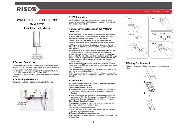
Risco RWT6F User manual

Risco

Risco RWT6F User manual

Risco ViTRON RWT6G User manual

Risco

Risco ViTRON RWT6G User manual

Risco Lumin8 4012 User manual

Risco

Risco Lumin8 4012 User manual

Risco RWX106BA User manual

Risco

Risco RWX106BA User manual

Risco DigiSense Digi-412DTPT User manual

Risco

Risco DigiSense Digi-412DTPT User manual

Risco WatchIN RK325DT User manual

Risco

Risco WatchIN RK325DT User manual

Risco iWave RWX95 User manual

Risco

Risco iWave RWX95 User manual

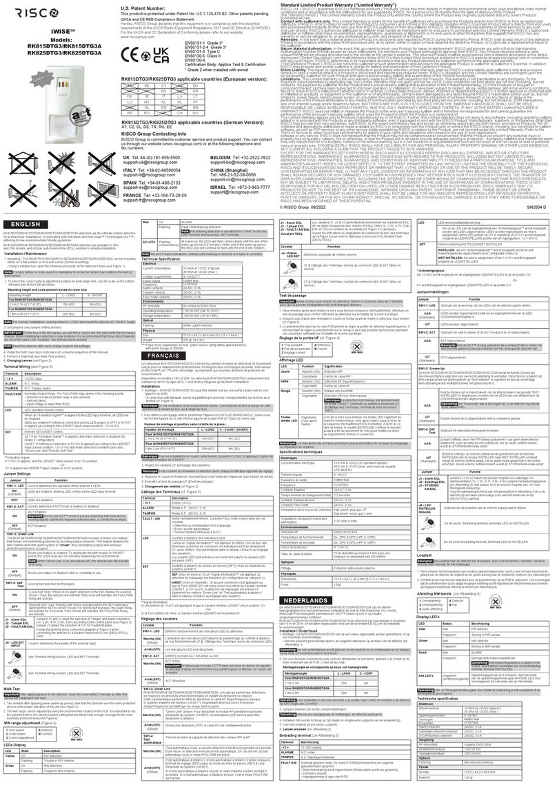
Risco iWISE RK815DTG3 User manual

Risco

Risco iWISE RK815DTG3 User manual

Risco PIR 4150200A User manual

Risco

Risco PIR 4150200A User manual

Risco ShockTec 600S User manual

Risco

Risco ShockTec 600S User manual

Risco BWare RK515DTG3 User manual

Risco

Risco BWare RK515DTG3 User manual

Risco iREX User manual

Risco

Risco iREX User manual

Risco Bware RWX515PR User manual

Risco

Risco Bware RWX515PR User manual

Risco LuNAR User manual

Risco

Risco LuNAR User manual

Risco WiComm Pro Instruction manual

Risco

Risco WiComm Pro Instruction manual

Risco iWISE QUAD AM Grade 3 User manual

Risco

Risco iWISE QUAD AM Grade 3 User manual

Risco RWT6FW43300A User manual

Risco

Risco RWT6FW43300A User manual

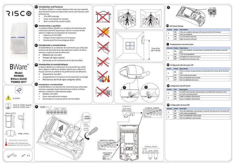
Risco BWare RK500Q User manual

Risco

Risco BWare RK500Q User manual

Risco iWISE QUAD AM Grade 3 User manual

Risco

Risco iWISE QUAD AM Grade 3 User manual

Risco LUNAR DT RK150 User manual

Risco

Risco LUNAR DT RK150 User manual

Risco iWAWE RWX95P User manual

Risco

Risco iWAWE RWX95P User manual

Risco WatchOUT XTreme 315DT User manual

Risco

Risco WatchOUT XTreme 315DT User manual

Risco Digi-415DT User manual

Risco

Risco Digi-415DT User manual

Risco BWare RK515DTGL User manual

Risco

Risco BWare RK515DTGL User manual

Popular Security Sensor manuals by other brands

Berthold GAMMAcast LB 6739 operating manual

Berthold

Berthold GAMMAcast LB 6739 operating manual

AFRISO LAG-14 ER operating instructions

AFRISO

AFRISO LAG-14 ER operating instructions

MSA General Monitors TL105 instruction manual

MSA

MSA General Monitors TL105 instruction manual

Baumer UNAM 50U6121 manual

Baumer

Baumer UNAM 50U6121 manual

Genesis LG2 WP-3020 Installation handbook

Genesis

Genesis LG2 WP-3020 Installation handbook

Andor Technology Newton user guide

Andor Technology

Andor Technology Newton user guide

GENEVO PRO II manual

GENEVO

GENEVO PRO II manual

Prime Controls DS3410 operating instructions

Prime Controls

Prime Controls DS3410 operating instructions

PNI SafeHouse HS003LR user manual

PNI

PNI SafeHouse HS003LR user manual

Chemtronics MDRAI302 user manual

Chemtronics

Chemtronics MDRAI302 user manual

Niko XXX-7802 Series quick start guide

Niko

Niko XXX-7802 Series quick start guide

BEMKO SES05BL-B instructions

BEMKO

BEMKO SES05BL-B instructions

Bosch TriTech+ ISC-PDL1-WA18G installation instructions

Bosch

Bosch TriTech+ ISC-PDL1-WA18G installation instructions

TS-market LORNET-36 user manual

TS-market

TS-market LORNET-36 user manual

Prime DS100 operating instructions

Prime

Prime DS100 operating instructions

ADEC Technologies TDC3 F-F-31 Series Quick reference guide

ADEC Technologies

ADEC Technologies TDC3 F-F-31 Series Quick reference guide

LuxHome LHD100SU Instruction guide

LuxHome

LuxHome LHD100SU Instruction guide

Gewiss Chorus GW 90 787 manual

Gewiss

Gewiss Chorus GW 90 787 manual

manuals.online logo
manuals.online logoBrands
  • About & Mission
  • Contact us
  • Privacy Policy
  • Terms and Conditions

Copyright 2025 Manuals.Online. All Rights Reserved.