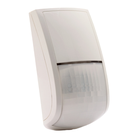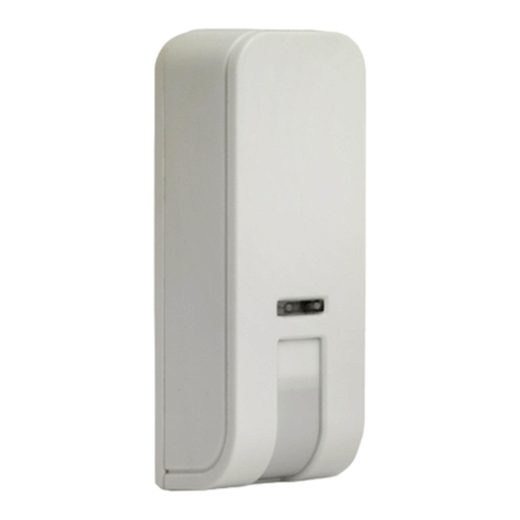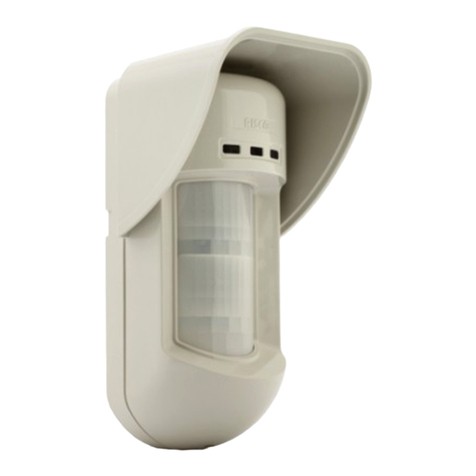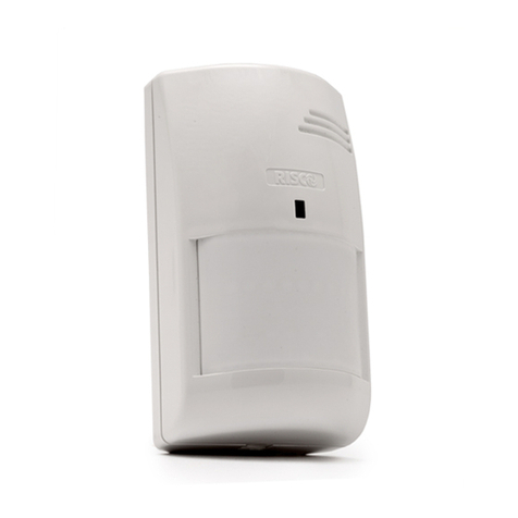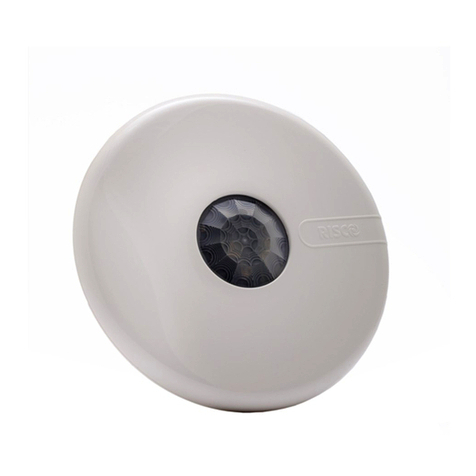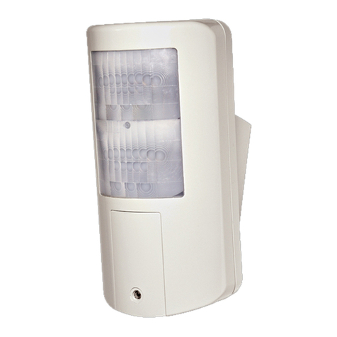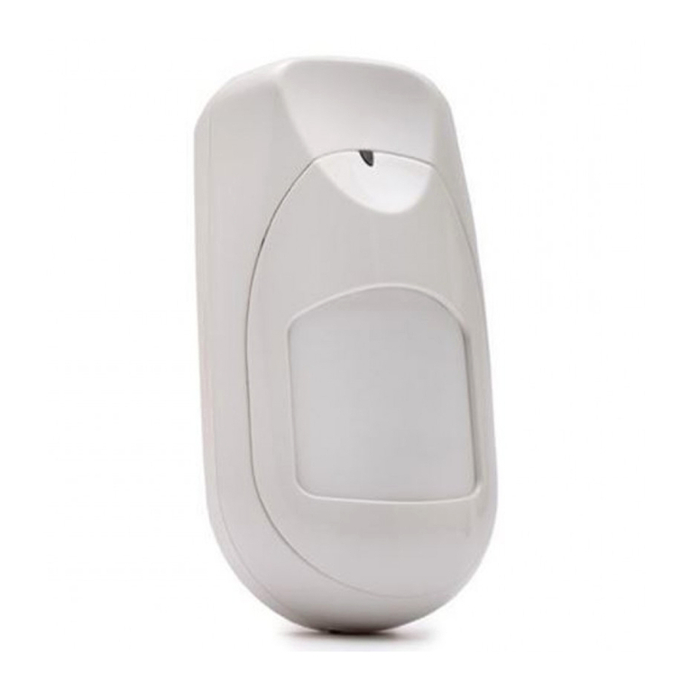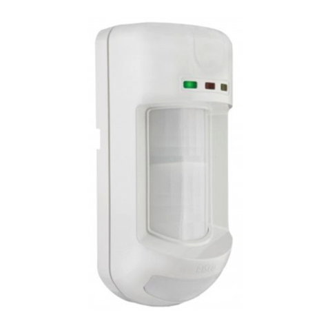
Walk Test Test Sensore Prueba de detección Test de Marche Prova de Moviento
FRIT PRES
© RISCO Group 06/2022 5IN2112 C
United Kingdom
Tel: +44-161-655-5500
support-uk@riscogroup.com
Spain
Tel: +34-91-490-2133
Belgium (Benelux)
Tel: +32-2522-7622
support-be@riscogroup.com
Contacting RISCO Group
RISCO Group is committed to customer service and product support. You can contact
us through our website www.riscogroup.com or as follows:
China (Shanghai)
Tel: +86-21-52-39-0066
Italy
Tel: +39-02-66590054
France
Tel: +33-164-73-28-50
Israel
Tel: +972-3963-7777
= ON
CD
A B = 2 Min
2 Min. (Max)
7
RISCO Group Limited Warranty
RISCO Ltd., its subsidiaries and affiliates (the "Seller") warrants its products to be free from
defects in materials and workmanship under normal use for 24 months from the date of
production.
Because the Seller does not install or connect the product, and because the product may be
used in conjunction with products not manufactured by the Seller, the Seller cannot
guarantee the performance of the security system which uses this product.
The Seller's obligation and liability under this warranty is expressly limited to repairing and
replacing, at the Seller's discretion, within a reasonable time after the date of delivery, any
product not meeting these specifications.
The Seller makes no other warranty, expressed or implied, and makes no warranty of
merchantability or of fitness for any particular purpose.
Under no circumstances should the Seller be liable for any consequential or incidental
damages for breach of this or any other warranty, expressed or implied, or upon any other
basis of liability whatsoever.
The Seller's obligation under this warranty shall not include any transportation charges or
costs of installation or any liability for direct, indirect, or consequential damages or delay.
The Seller does not warrant that the product may not be compromised or circumvented;
that the product will prevent any personal injury or property loss by burglary, robbery, fire
or otherwise; or that the product will in all cases provide adequate warning or protection.
The buyer/customer understands that a correctly installed and maintained alarm may only
reduce the risk of burglary, robbery or fire without warning, but is not an insurance or a
guarantee that such an event will not occur or that there will be no personal injury or
property loss as a result thereof.
Consequently the Seller shall have no liability for any personal injury, property damage or
loss based on a claim that the product fails to give warning.
However, if the Seller is held liable, whether directly or indirectly, for any loss or damage
arising under this limited warranty or otherwise, regardless of cause or origin, the Seller's
maximum liability shall not exceed the purchase price of the product, which shall be a
complete and exclusive remedy for the Seller.
No employee or representative of the Seller is authorized to change this warranty in any
way or grant any other warranty.
Batteries installed in or used with the products are explicitly excluded from this or any other
warranty. Seller gives no warranty whatsoever as to batteries and buyer's only remedy (if
any) shall be in accordance with the warranty provided (if and to the extent provided) by
the manufacturers of batteries.
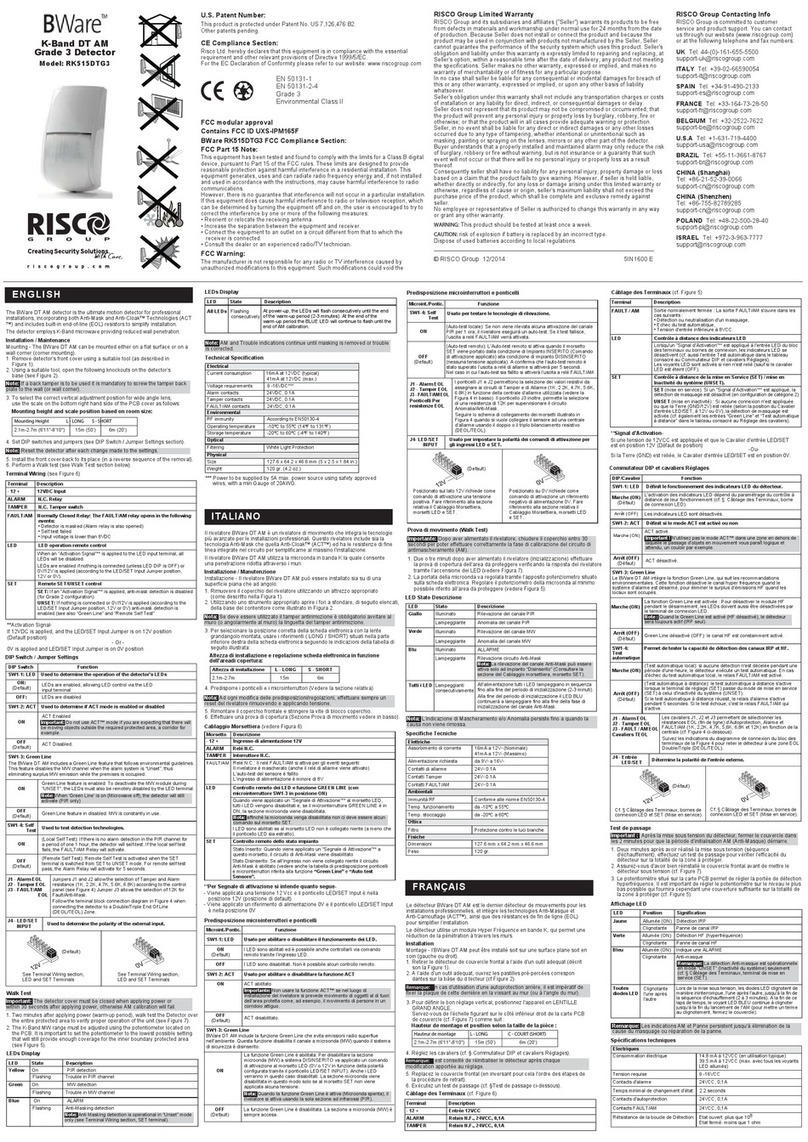
Yellow
LED
LED Display
State
On
Description
PIR channel 2 Detection
Flashing Trouble in PIR channel 2
Green On PIR channel 1 detection
Flashing Trouble in PIR channel 1
Blue
On Alarm
Flashing Communication Trouble
Rapid Flashing Anti-Masking detection
All
LEDs
Flashing
(consecutively)
At power-up, the LEDs will flash consecutively
until the end of the warm-up period (2-3
minutes). At the end of the warm-up period the
BLUE LED will continue to flash until the end of
AM calibration.
EN
Amarillo
LED
Indicación de los LEDs
Estado
Encendido
Descripción
Detección canal PIR 2
Parpadeando Problema en el canal PIR 2
Verde Encendido Detección canal PIR 1
Parpadeando Problema en el canal PIR 1
Azul
Encendido Indicación de ALARMA
Parpadeando Problema de comunicación
Parpadeo RápidoDetección Anti-Enmascaramiento
Todos
los
LEDs
Parpadeando
(consecutivame
nte)
Al dar alimentación, los LEDs
parpadearán consecutivamente hasta
que finalice el periodo de calentamiento
(2-3 minutos). Al finalizar el periodo de
calentamiento, el LED AZUL seguirá
parpadeando hasta que termine la
calibración del AM.
ES
Giallo
LED
Indicatori LED
Stato
Illuminato
Descrizione
Rilevazione del 2° canale all’infrarosso passivo (PIR)
Lampeggiante Anomalia del 2° canale PIR
Verde Illuminato Rilevazione del 1° canale PIR
Lampeggiante Anomalia del 1° canale PIR
Blu
Illuminato ALLARME
Lampeggiante Problema di comunicazione
Lampeggiante
Rapido Anomalia / Rilevazione circuito Anti-Mask
Tutti i
LED
Lampeggiante
(consecutivame
nte)
All’alimentazione tutti i LED lampeggiano in
sequenza fino alla fine del periodo di
preriscaldamento (2-3 minuti). Alla fine del
periodo di preriscaldamento il LED BLU
continuerà a lampeggiare fino alla fine della
fase di inizializzazione del canale Anti-Mask.
IT
Jaune
LED
Affichage LED
Etat
Allumée
Description
Détection canal 2 IRP
Clignotante Défaut canal 2 IRP
Verte Allumée Détection canal 1 IRP
Clignotante Défaut canal 1 IRP
Bleu
Clignotante Défaut de communication
Clignotante
rapide Défaut d’Anti-masque
Totalité
LED’s
Clignotante
(consécutivement)
Au démarrage, les voyants LED clignotent
successivement jusqu'à la fin de la période
d'échauffement (2-3 minutes). A la fin de la
période d'échauffement la LED bleue
continuera à clignoter jusqu'à la fin de
l'étalonnage AM.
FR
Amarelo
LED
Visualizacão dos LEDs
Estado
Aceso
Descricao
Detecção de Infravelmenho Passivo 2
Piscado Problema no canal Infravelmenho Passivo 2
Verde Aceso Detecção de Infravelmenho Passivo 1
Piscado Problema no canal Infravelmenho Passivo 1
Azul
Aceso ALARME
Piscado Problema de comunicação
Piscado Rápido Falha/ Detecção Anti Máscara.
Todos os
LEDs
Piscado
(sucessivamante)
Ao conectar, os LEDs piscarão
consecutivamente até o final do período de
aquecimento (2-3minutos). Ao final do
período de aquecimento, o LED AZUL
continuará piscando até o final da iniciação
do AM.
PR
RL0004V (Wide Angle)
Wide Angle – Side View
Wide Angle – Top View
System Programming:
1. Add/delete a BWare BUS detector
• Installer menu [7] Accessories / Install > [1] Add Delete Module > [9] More.. > [5] BUS Zone.
• Select ID (as defined by the Dip switches) and define type as BQUG3.
2. Assign the BWare BUS detector to a Zone
• Installer menu [2] Zones > [1] One by One > Select Zone.
• Under Termination select > [5] BUS Zone.
• Select the BUS zone number to assign to the programmed zone.
3. Program the zone input on the BWare BUS
• Installer menu [2] Zones > [1] One by One > Select Zone.
• Under Termination select from options [07] to [11].
• Press [#]. Select the BUS zone that the input zone belongs to.
4. Configure the BWare BUS detector parameters.
• Installer menu select [2] Zones > [0] Miscellaneous > [3] BUS Zone Parameters. Refer to System Installation Manual.
Programmazione Sistema:
ProSYS: 1. Aggiungi/cancella un rivelatore BUS BWare
• Menù Tecnico [7] Accessori > [1] Agg./Canc.Modulo > [9] Continua.. > [5] Zone BUS
• Selezionare il numero ID (come impostato dai microinterrutori) e definire il tipo come BQUG3
2. Assegnazione del rivelatore BUS BWare ad una Zona
• Menù Tecnico [2] Zone > [1] Una per Una > Selezionare il numero di zona
• Raggiunta l'opzione Terminazione selezionare > [5] Zona BUS
• Selezionare il numero ID della zona BUS da assegnare alla zona che si sta programmando
3. Programmazione dell'ingresso di zona aggiuntivo sul rivelatore BUS BWare
• Menù Tecnico [2] Zone > [1] Una per Una > Selezionare il numero di zona
• Raggiunta l'opzione Terminazione selezionare una delle opzioni da [07] a [11]
• Premere [#]. Selezionare il numero ID della zona BUS che fa riferimento all'ingresso di zona che si sta programmando
4. Configurazione dei parametri del rivelatore BUS Bware
• Nel Menù Tecnico selezionare [2] Zone > [0] Varie > [3] Parametri Zone BUS > Selezionare il numero di zona al
quale è stato assegnato il rivelatore. Fare riferimento al Manuale Tecnico della centrale per i parametri del rivelatore
LightSYS: 1. Aggiungi/cancella un rivelatore BUS Bware
• Menù Tecnico [7] Configurazione > [1] Accessori BUS > [2] Configurazione Manuale > [9] Zone-BUS
• Selezionare l’identificativo ID (come impostato dai microinterruttori) e definire il Tipo come BQUG3
3. Programmare l’ingresso di zona del rivelatore BWare BUS
• Una volta completata l’operazione descritta al punto 1, la centrale automaticamente chiederà se aggiungere alla
zona sucessiva l’ingresso di zona aggiuntivo del rivelatore
4. Programmare i parametri del rivelatore
• Menù Tecnico [2] Zone > [1] Parametri > [2] Per Parametro > [7] Avanzati > [4] Zone BUS > Selezionare il numero di
zona al quale è stato assegnato il rivelatore. Fare riferimento al Manuale Tecnico della centrale per i parametri del
rivelatore
Programación Sistema:
1. Añadir/Borrar un detector BWare BUS
• Menú Instalador > [7] Accesorios > [1] Agregar/Borrar Módulo > [9] Más... > [5] Zonas BUS
• Seleccione el ID (según se haya definido con los microinterruptores DIP) y defina el tipo como BQUG3
2. Asignar el detector BWare BUS a una Zona
• Menú Instalador > [2] Zonas > [1] Una a Una > Seleccione la Zona
• En el apartado Terminación, seleccione la opción [05] Zona BUS.
• Seleccione el ID del detector BUS que se va a asignar a la zona programada.
3. Programar la entrada de zona adicional del BWare BUS
• Menú Instalador > [2] Zonas > [1] Una a Una > Seleccione la Zona.
• En el apartado Terminación, seleccione una de las opciones de la [07] a la [11].
• Presione [#]. Seleccione el ID del detector BUS al que pertenece la entrada de zona.
4. Configuración de los parámetros del detector BWare BUS.
• Menú Instalador > [2] Zonas > [0] Varios > [3] Parámetros Zona BUS. Consulte el manual de instalación del sistema
para la configuración de los parámetros del detector BUS.
Programmation Système:
1. Ajout/Supp détecteur BWare BUS
• Menu Installateur [7] Accessoires / Installation > [1] Ajout/Supp Module > [9] Plus. > [5] Zone BUS.
• Sélectionner l’ID (défini par les Dip switches) et définir le type en BQUG3
2. Assigner le détecteur BWare BUS à une Zone
• Menu Installateur [2] Zones > [1] Une par Une > Sélectionner Zone.
• Dans Nature sélectionner > [5] BUS Zone.
• Sélectionner le numéro de la zone BUS à assigner à la zone programmée.
3. Programmer la zone d’entrée du BWare BUS
• Menu Installateur [2] Zones > [1] Une par Une > Sélectionner Zone.
• Dans Nature sélectionner les options [07] à [11].
• Appuyer sur [#].Sélectionner le numéro de la zone BUS à assigner à la zone programmée.
4. Configurer les paramètres du détecteur BWare BUS.
• Menu Installateur sélectionner [2] Zones > [0] Divers > [3] Param Zone BUS. Reportez-vous au manuel d'installation
du système pour les paramètres des détecteurs BUS.
Programação da Sistema:
1. Adicionar/Apagar um detector BWare BUS
• Menu do instalador [7] Acessórios > [1] Adicionar/Apagar módulo > [9] Mais.. > [5] Zonas de BUS.
• Selecionar ID (como definido nos Dipswitches) e definir como o tipo BQUG3
2. Alocar o BWare BUS à uma zona
• Menu do Instalador [2] Zonas > [1] Uma a Uma > Selecionar Zona.
• No menu de Terminação selecione > [5] Zona de BUS.
• Selecione o número da zona de BUS para alocar a zona programada.
3. Programação da entrada de zona do BWare BUS
• Menu do instalador [2] Zonas > [1] Uma a uma > Selecionar Zona.
• No menu de terminação escolha uma das opções de [07] até [11].
• Apertar [#]. Escolher a zona de BUS que a entrada de zona pertence.
4. Configurar os parâmetros do detector BWare BUS.
• Selecionar o menu do instalador [2] Zonas > [0] Diversos > [3] Parâmetros de Zonas de BUS.
FR
ES
IT
EN
6
EN
PR
UKCA and CE EMC Compliance Statement
Hereby, RISCO Group declares that this equipment is in compliance with the essential
requirements of the UKCA Electromagnetic Compatibility Regulations 2016 and CE Directive
2014/30/EU.
For the UKCA and CE Declaration of Conformity please refer to our website:
www.riscogroup.com


