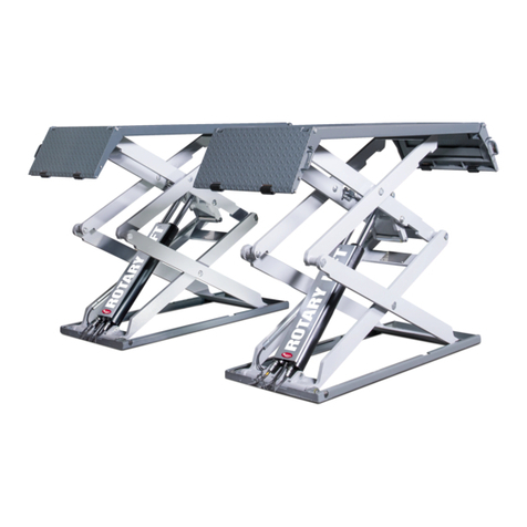
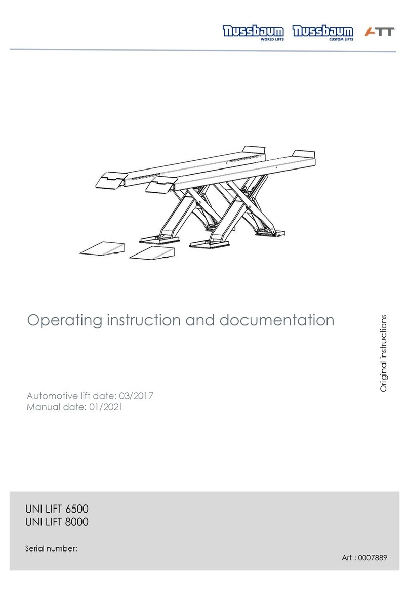
Rotary 300 Series Manual

O
P
E
R
A
T
I
O
N
&
M
A
I
N
T
E
N
A
N
C
E
M
A
N
U
A
L
O
P
E
R
A
T
I
O
N
&
M
A
I
N
T
E
N
A
N
C
E
M
A
N
U
A
L
Table of Contents
SAFETY INSTRUCTIONS..................................................................... 2
OWNER/EMPLOYER RESPONSIBILITIES ........................................ 3
OPERATING INSTRUCTIONS ............................................................. 4
MAINTENANCE INSTRUCTIONS ...................................................... 6
TROUBLE SHOOTING .......................................................................... 7
OM20201
Entire contents © May 2010 by Rotary Lift. All rights reserved. CO7585.1 Rev. C 05/06/10
LP20469
RLP35
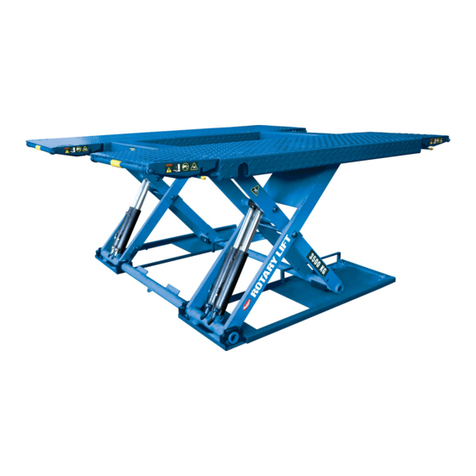
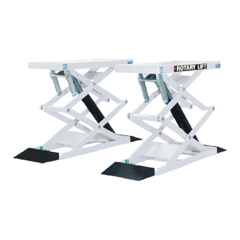
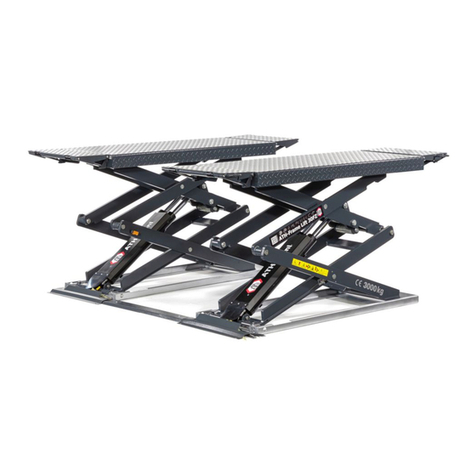
Scissor Lift
(300 Series)
Capacity 7700 lbs (3500 kg)
(Maximum 3,850 lbs (1750 kg) per pad)
B
M
W
B
M
W

2
• Daily inspect your lift. Never operate if it malfunctions
or if it has broken or damaged parts. Use only qualified
lift service personnel and genuine Rotary parts to make
repairs.
• Thoroughly train all employees in use and care of lift,
using manufacturer’s instructions and “Lifting It Right”
and “Safety Tips” supplied with the lift.
• Never allow unauthorized or untrained persons to
position vehicle or operate lift.
• Prohibit unauthorized persons from being in shop area
while lift is in use.
• DoNot permit anyone on lift or inside vehicle when it is
either being raised or lowered.
• Always keep area around lift free of tools, debris, grease
and oil.
• Never overload lift. Capacity of lift is 7,700 lbs/3500kg.,
3850 lbs/1750kg. per platform.
• DoNotstand in front of the lift or vehicle while it is being
positioned in lift bay.
• Beforedriving vehicle into lift bay, BE SURE lift is fully
lowered.
• Loadvehicle on lift carefully. Check for secure contact
with vehicle. Raise lift to desire working height.
• DoNot block open or override self-closing lift controls;
they are designed to return to the “Off” or Neutral
position when released.
• Remain clear of lift when raising or lowering vehicle.
• Always lower lift completely and disconnect power
source before disconnecting hydraulic lines.
• Avoid excessive rocking of vehicle while on lift.
• Clear area if vehicle is in danger of falling.
• Completely lower lift before removing vehicle from lift
area.
• Normal operating temperature range is 7° C (45° F) To 38°
(100° F).
SAFETY INSTRUCTIONS

3
TheOwner/Employer:
• Shallensurethatliftoperatorsarequaliedandthattheyaretrainedinthesafe
use and operation of the lift using the manufacturer’s operating instructions;
ALI/SM 93-1, ALI Lifting it Right safety manual; ALI/ST-90 ALI Safety Tips card;
ANSI/ALI ALOIM-2008, American National Standard for Automotive Lifts-Safety
Requirements for Operation, Inspection and Maintenance; ALI/WL Series, ALI
Uniform Warning Label Decals/Placards; and in the case of frame engaging lifts,
ALI/LP-GUIDE, Vehicle Lifting Points/Quick Reference Guide for Frame Engaging
Lifts.
• Shallestablishprocedurestoperiodicallyinspecttheliftinaccordancewith
the lift manufacturer’s instructions or ANSI/ALI ALOIM-2008, American National
Standard for Automotive Lifts-Safety Requirements for Operation, Inspection
and Maintenance; and The Employer Shall ensure that lift inspectors are quali-
fied and that they are adequately trained in the inspection of the lift.
• Shallestablishprocedurestoperiodicallymaintaintheliftinaccordancewith
the lift manufacturer’s instructions or ANSI/ALI ALOIM-2008, American National
Standard for Automotive Lifts-Safety Requirements for Operation, Inspection
and Maintenance; and The Employer Shall ensure that lift maintenance person-
nel are qualified and that they are adequately trained in the maintenance of the
lift.
• Shallmaintaintheperiodicinspectionandmaintenancerecordsrecommended
by the manufacturer or ANSI/ALI ALOIM-2008, American National Standard for
Automotive Lifts-Safety Requirements for Operation, Inspection and Mainte-
nance.
• Shalldisplaytheliftmanufacturer’soperatinginstructions;ALI/SM93-1,ALI
Lifting it Right safety manual; ALI/ST-90 ALI Safety Tips card; ANSI/ALI ALO-
IM-2008, American National Standard for Automotive Lifts-Safety Requirements
for Operation, Inspection and Maintenance; and in the case of frame engaging
lifts, ALI/LP-GUIDE, Vehicle Lifting Points/Quick Reference Guide for Frame En-
gaging Lifts; in a conspicuous location in the lift area convenient to the operator.
• Shallprovidenecessarylockout/tagoutmeansforenergysourcesperANSI
Z244.1-1982 (R1993), Safety Requirements for the Lockout/Tagout of Energy
Sources, before beginning any lift repairs.
• Shallnotmodifytheliftinanymannerwithoutthepriorwrittenconsentofthe
manufacturer.
OWNER/EMPLOYER RESPONSIBILITIES

4
LOCKOUT/TAGOUTPROCEDURE
Purpose
This procedure establishes the minimum requirements for the lockout of energy that could cause injury to personnel by the
operation of lifts in need of repair or being serviced. All employees shall comply with this procedure.
Responsibility
The responsibility for assuring that this procedure is followed is binding upon all employees and service personnel from
outside service companies (i.e., Authorized Rotary Installers, contactors, etc.). All employees shall be instructed in the
safety significance of the lockout procedure by the facility owner/manager. Each new or transferred employee along with
visiting outside service personnel shall be instructed by the owner/manager (or assigned designee) in the purpose and use
of the lockout procedure.
Preparation
Employees authorized to perform lockout shall ensure that the appropriate energy isolating device (i.e., circuit breaker,
fuse, disconnect, etc.) is identified for the lift being locked out. Other such devices for other equipment may be located in
close proximity of the appropriate energy isolating device. If the identity of the device is in question, see the shop supervi-
sor for resolution. Assure that proper authorization is received prior to performing the lockout procedure.
SequenceofLockoutProcedure
1) Notify all affected employees that a lockout is being performed and the reason for it.
2) Unload the subject lift. Shut it down and assure the disconnect switch is “OFF” if one is provided on
the lift.
3) The authorized lockout person operates the main energy isolation device removing power to the sub-
ject lift.
• Ifthisisalockabledevice,theauthorizedlockoutpersonplacestheassignedpadlockonthe
device to prevent its unintentional reactivation. An appropriate tag is applied stating the person’s
name, at least 3” x 6” in size, an easily noticeably color, and states not to operate device
or remove tag.
• Ifthisdeviceisanon-lockablecircuitbreakerorfuse,replacewitha“dummy”deviceandtagit
appropriately as mentioned above.
4) Attempt to operate lift to assure the lockout is working. Be sure to return any switches to the “OFF”
position.
5) The equipment is now locked out and ready for the required maintenance or service.
RestoringEquipmenttoService
1) Assure the work on the lift is complete and the area is clear of tools, vehicles, and personnel.
2) At this point, the authorized person can remove the lock (or dummy circuit breaker or fuse) & tag
and activate the energy isolating device so that the lift may again be placed into operation.
RulesforUsingLockoutProcedure
Use the Lockout Procedure whenever the lift is being repaired or serviced, waiting for repair when current operation could
cause possible injury to personnel, or for any other situation when unintentional operation could injure personnel. No at-
tempt shall be made to operate the lift when the energy isolating device is locked out.

5
OPERATING INSTRUCTIONS
Toavoidpersonalinjuryand/orpropertydamage,permitonlytrainedpersonneltooperatelift.
Afterreviewingtheseinstructions,getfamiliarwithliftcontrolsbyrunningtheliftthrougha
fewcyclesbeforeloadingvehicleonlift.
Alwaysliftthevehicleusingallfouradapters.NEVERraisejustoneend,onecorner,oronesideofvehicle.
IMPORTANT
WARNING
ObserveandheedSAFETY,CAUTIONandWARNING labels
onthelift.
1. BeforeLoading:
• Inspectlifttoassureitisingoodoperationcondition.
2. Loading:
• Assureliftisfullyloweredandservicebayisclearofall
personnel.
• Driveoverrampsandspotvehiclewithleftfrontwheel
as shown in , Fig. 2.
• DONOTraiselimousinesorpickuptrucks.
• DONOTraiseSUV's,vans,orotherspecialtyvehicles
notofaunibodyconstruction.
WARNING
Beforeattemptingtoliftvehiclebesure
that:
• VehicleispositionedoverpadsasshowninFig.3&4.
• Vehicleunibodyisstrongenoughtosupportit'sweight
and has not been weakened by modification of corrosion.
• Vehicleindividualaxleweightdoesnotexceed1/2lift
capacity.
• Sliderearpadextensionasnecessarytoreachrearlift
points.
• Useauxiliaryrubberblockstocreateclearancebetween
vehicle chassis and lift pad, Fig. 4.
• Auxiliaryrubberblocks/padsareinsecurecontactwith
vehiclemanufacture'srecommendedliftpoints.
• Vehicleisstableonlift;neitherfrontnortailheavy.
3. ToRaiseLift:
• ActuateRAISEBUTTON.
• Raisevehicleuntiltirescleartheoor.
• STOP:Checkpadsforsecurecontactwithvehicle.
Shake car moderately at front or rear bumper.
• ContinuetoraisetodesiredheightONLY if vehicle is
secure on lift. If necessary, lower lift and reposition
usingvehiclemanufacture'srecommendedpick-up
points.
4.BeforeLoweringLift:
• Removeallobstaclesfromundervehicleandlift.
• Assurepersonnelarenotinliftarea.
5.ToLowerLift:
• Remainclearoflift.
• ActuatetheLOWERBUTTONtolowerliftwhilekeeping
feet clear.
• Whentheliftstops,actuateagainLOWERBUTTON
to fully lower lift.
6.Unloading:
• Assureliftisfullylowered.
• Removeanyrubberblocksusedwhenraisingthe
vehicle.
• Returnrearpadextensiontofullyclosedposition.
• Carefullyremovevehiclefromliftarea.
Other manuals for 300 Series
1
This manual suits for next models
1
Table of contents
Other Rotary Scissor Lift manuals

Rotary
Rotary 100 Series User manual

Rotary
Rotary M50 Manual

Rotary
Rotary S50 Troubleshooting guide

Rotary
Rotary SM40 Manual

Rotary
Rotary GLP 35 User manual

Rotary
Rotary 000 Series Manual

Rotary
Rotary 000 Series User manual

Rotary
Rotary GLP 35 User manual

Rotary
Rotary GLP 35 User manual

Rotary
Rotary GEMINI GLP 30 User manual