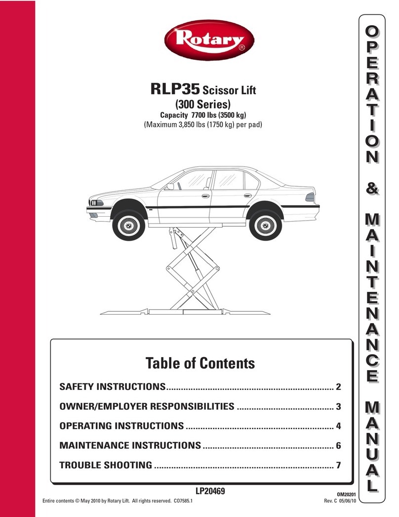
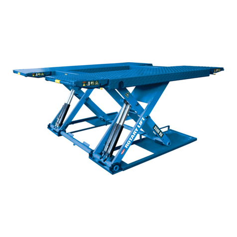
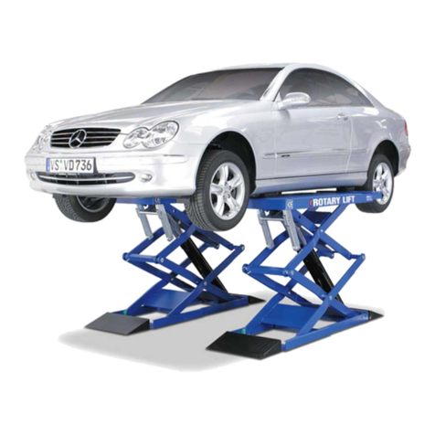
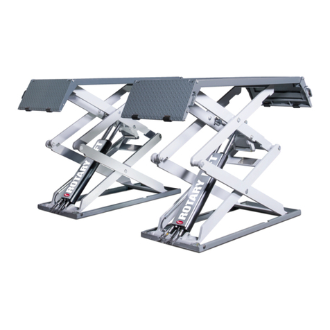
Rotary M50 Manual

M50
Scissor Lift
Rotary Lift Rev.C 03/2013


EC Declaration of Conformity
according to EU machine directive 2006/42/EG (Annex II A)
Name and address of manufacturer: BlitzRotary GmbH
Hüfinger Str.55
78199 Bräunlingen,
Germany
This declaration only relates to the machine in condition as supplied; components added and/or subsequent
modifications made by the end user are disregarded. This declaration becomes invalid if the product is
changed or modified without permission.
We declare that the undermentioned machine,
Product name: SCISSOR LIFT
Serial / type name: M 50, ML 40, ML 50
Machine/serial number: .............................................................
Year of manufacture: 20…
complies with all relevant provisions or the machine directive 2006/42/EG.
In addition the machine complies with the provisions of the directives 2004/108/EG electro-magnetic compat-
ibility (safety objectives were complied with according to Annex I, no. 1.5.1 machine directive 2006/42/EG).
Applied harmonized standards:
EN 1493:1998+A1:2008 Vehicle lifts
EN ISO 12100-1 : 2003 Safety of machinery –Basic concepts
EN ISO 12100-2 : 2003 Safety of machinery –Basic concepts
EN 60204-1:2006+7/2007 Electrical equipment of machines
EN 349:1993+A1:2008 Safety of machinery –Minimum gaps
EN ISO 13850:2008 Safety of machinery –Emergency stop
Other applied technical standards and specifications:
BGG 945 Inspections of lifts
BGR 500 Operation of work equipment
BGV A3 Accident prevention regulation electric equipment and production equipment
EU prototype examination no.: D 06 AA3887101
EU notified body No. 0124 , DEKRA certification
Representative for the compilation of relevant technical documentation
BlitzRotary GmbH, Hüfinger Str. 55, 78199 Bräunlingen
Place, date
Bräunlingen, 20.03.2013 ___________________________
Frank Scherer / Managing Director
DECLARATION OF WARRANTY AND LIMITATION OF LIABILITY
The manufactures has paid proper attention to the preparation of this manual. However, nothing
contained herein modifies or alters, in any way, the terms and conditions of manufacturer
agreement by which this lift was acquired, nor increase, in any way, manufacturer’s liability to the
customer.
TO THE READER
Every effort has been made to ensure that the information contained in this manual is correct,
complete and up-to date. The manufacturer is not liable for any mistakes made when drawing up
this manual and reserves the right to make any changes due the development of the product, at any
time.
BlitzRotary GmbH
Hüfinger Straße 55
78199 Bräunlingen
Germany

PRINTING CHARACTERS AND SYMBOLS
Throughout this manual, the following symbols and printing characters are used to facilitate
reading:
Indicates the operations which need proper care
Indicates prohibition
Indicates a possibility of danger for the operators
Indicates the direction of access for motor vehicles on to the lift
Bold Type
Important information
WARNING: before operating this lift and carrying out any adjustment. read
chapter 7 “installation” where the correct installation procedures for the lift
are shown.

CONTENTS
1
GENERAL INFORMATION
4
2
PRODUCT IDENTIFICATION
6
3
PACKING, TRANSPORT AND STORAGE
7
4
PRODUCT DESCRIPTION
10
5
TECHNICAL SPECIFICATION
15
6
SAFETY
43
7
INSTALLATION
46
8
OPERATION AND USE
61
9
MAINTENANCE
67
10
TROUBLESHOOTING
69
11
EC DECLARATION OF CONFORMITY
71

1 CHAPTER 1 –GENERAL INFORMATION
This chapter contains warning instructions to operate the lift properly and prevent injury to
operators or objects.
This manual has been written to be used by shop technicians in charge of the lift (OPERATORS) and
routine maintenance technicians (MAINTENANCE OPERATORS).
The operating instructions are considered to be an integral part of the machine they and must remain
with the lift at all times. Read every section of this manual carefully before unpacking and operating
the lift. the manual gives helpful information about::
-SAFETY OF PEOPLE
-SAFETY OF THE LIFT
-SAFETY OF LIFTED VEHICLES
The company is not liable for possible problems, damage, accidents, etc. resulting from failure to
follow the instructions contained in this manual.
Only skilled technicians of AUTHORISED DEALERS or SERVICE CENTRES AUTHORISED
by the manufacturer shall be allowed to carry out lifting, transport, assembling, installation,
adjustment, calibration, settings, extraordinary maintenance, repairs, overhauling and dismantling of
the lift.
THE MANUFACTURER IS NOT RESPONSIBLE FOR POSSIBLE DAMAGE TO PEOPLE,VEHICLES OR
OBJECTS IF SAID OPERATIONS ARE CARRIED OUT BY UNAUTHORISED PERSONNEL OR THE LIFT IS
IMPROPERLY USED.
Any use of the machine made by operators who are not familiar with the instructions and
procedures contained herein shall be forbidden.
1.1 MANUAL KEEPING
For proper use of this manual, the following is recommended:
keep the manual near the lift, in an easily accessible place
keep the manual in an area protected from the damp
use this manual properly without damaging it
do not make changes to the manual; any changes and updating can be made only by the
manufacturer.
This manual is an integral part of the lift: it shall be given to the new owner if and when the lift is
resold.
1.2 OBLIGATION IN CASE OF MALFUNCTION
In case of machine malfunction, follow the instructions contained in the following
chapters.
1.3 CAUTIONS FOR THE SAFETY OF THE OPERATOR
Operators must not be under the influence of sedatives, drugs or alcohol when operating the
machine.

Before operating the lift, operators must be familiar with the position and function
of all controls, as well as with the machine features shown in the chapter
“Operation and use”.
1.4 WARNINGS
Unauthorized changes and/or modifications to the machine relieve the
manufacturer of any liability for possible damages to objects or people. Do not
remove or make inoperative the safety devices, this would cause a violation of
safety at work laws and regulations.
Any other use which differs from that provided for by the manufacturer of the
machine is strictly forbidden.
The use of non genuine parts may cause damage to people or objects.

2 CHAPTER 2 –PRODUCT IDENTIFICATION
The identification data of the machine are shown in the label placed on the frame and indicated in
the declaration of conformity.
Use the above data both to order spare parts and in case of enquires with the
manufacturer (inquiry). The removal of this label is strictly forbidden.
Machines may be updated or slightly modified from an aesthetic point of view and, as a
consequence, may present features different from these shown, this without prejudicing what has
been described herein.
2.1 WARRANTY CERTIFICATE
The warranty is valid for a period of 12 months starting from the date of the purchase invoice.
The warranty will end immediately when unauthorized modifications to the machine or parts of it
are carried out.
The presence of defects in workmanship must be verified by the Manufacturer’s personnel in
charge.
2.2 TECHNICAL SERVICING
For all servicing and maintenance operations not specified or shown in these instructions, contact
your Dealer where the machine was bought or the Manufacturer’s Commercial Department.
LOGO
Type: ……….
Model: ……….
Serial Number: ……….
Year of manufacturing: ……….
Capacity: ……….
Voltage: ……….
Power: ……….
Max. pressure: ……….

3 CHAPTER 3 - PACKING, TRANSPORT AND STORAGE
Only skilled personnel who are familiar with the lift and this manual shall be allowed to carry out
packing, lifting, handling, transport and unpacking operations.
3.1 PACKING
The lift is supplied disassembled into sub-assemblies depending on the model ordered.
Model N:
N° 2 base units, each one with a flat runway and 2 hydraulic cylinders
N° 1 control unit equipped with hydraulic unit;
N° 1 box containing hydraulic lines, stickers and technical documentation;
N° 2 drive-on ramps with 2 stop wheels and 4 protective devices to connect runways for
on-floor installation or 4 drive-on ramps for in-ground installation.
Model AT:
N° 2 base units, each one with a runway equipped with recessing for the graduated plates
and slip plates for wheel alignment, and 2 hydraulic cylinders;
N° 1 control unit equipped with hydraulic unit
N° 1 box containing hydraulic lines, stickers and technical documentation;
N° 2 drive-on ramps with 2 stop wheels and 4 protective devices to connect runways for
on-floor installation or 4 drive-on ramps for in-ground installation.
Model LT:
N° 2 base units, each one with a flat runway equipped with lift-table for further lifting of
the vehicle, and 4 hydraulic cylinders;
N° 1 control unit equipped with hydraulic unit
N° 1 box containing hydraulic lines, stickers and technical documentation;
N° 2 drive-on ramps with 2 stop wheels and 4 protective devices to connect runways for
on-floor installation or 4 drive-on ramps for in-ground installation.
Model LTAT:
N° 2 base units, each one with a flat runway equipped with recessing for the graduated
plates and slip plates for wheel alignment, and lift-table for further lifting of the
vehicle, and 4 hydraulic cylinders;
N° 1 control unit equipped with hydraulic unit
N° 1 box containing hydraulic lines, stickers and technical documentation;
N° 2 drive-on ramps with 2 stop wheels and 4 protective devices to connect runways for
on-floor installation or 4 drive-on ramps for in-ground installation.
If requested, optional accessories are available to satisfy each customer’s requirements (Ref.
accessories manual and price lists).
The lift is packed in a single box on a wooden bed, wrapped up in non-scratch waterproof material
and sealed with 2 straps.
The average weight of the package changes between 2000 - 2600 Kg.

Figure 1 –MODELS TYPE
N
AT
LT
LTAT
3.2 LIFTING AND HANDLING
When loading/unloading or transporting the equipment to the site, be sure to use suitable loading
(e.g. cranes, trucks) and hoisting equipment. Hoist and transport the components securely so that
they cannot drop, taking into consideration the package’s size, weight and centre of gravity and
fragile parts.
In figure 2 there are the correct indications for the lifting of the runways during the connecting
cables phase:
1. runways lifting without play detector
2. runways lifting with support (ex. metal sheet) placed in the entry runway fixing plate
3. runways lifting with hydraulic play detector
4. lift lifting (pay attention to the hydraulic hoses).

Figure 2 –PACKAGE AND HANDLING
Hoist and handle only one package at a time
3.3 STORAGE AND STACKING OF PACKAGES
Packages must be stored in a covered area, out of direct sunlight and in low humidity, at a
temperature between -10°C and +40°C.
Stacking is not recommended: the package’s narrow base, as well as its considerable weight and
size make it difficult and hazardous.
If this was necessary, never stack more than three packages a time and fix them with straps, ropes
or other suitable means to ensure they are secure.
3.4 DELIVERY AND CHECKING OF PACKAGES
When the lift is delivered, check for possible damages due to transport and storage; verify its
conformity with what is specified in the manufacturer’s confirmation of order is included. In case
of damage in transit, the customer must immediately inform the carrier of the problem.
Packages must be opened paying attention not to cause damage to people (keep a safe distance
when opening straps) and parts of the lift (be careful the objects do not drop from the package
when opening).

4 CHAPTER 4 - PRODUCT DESCRIPTION
4.1 LIFT (Ref. Figure 3)
All models have been designed to lift motor-vehicles at any level between the minimum and
maximum height.
The maximum lifting weight, including any additional load on the vehicle, is as specified on the
serial plate.
All mechanical frames, such as platforms, extensions, base frames and arms have been built in a
pressure bend plant to make the frame rigid and strong while keeping a low weight
The electro hydraulic operation is described in detail in chapter 8
As shown in figure 3, the lifts is composed of two platforms, the platform 1 (1) and the platform 2
(2) anchored to the ground by means of two base frames (3)
The lift is equipped with 4 drive-up ramps (4) at the end of the platforms to facilitate the entry the
of vehicle.
Platforms, linked to the base frame by means of a scissors lifting system, is 4200 mm in length and
the lifting system of each platform is composed of two arms, external (5) and internal (6), as well
as a cylinder primary (7)in platform P1, and a secondary cylinder (8) in platform P2.
On both cylinders are installed mechanical safety devices. (9).
Lift lowering and lifting are carried out by means of a control box (17) (fixed to the ground) next
to the lift.
Models LT and LTAT, are equipped with an auxiliary lift or lift-table,(10) for further lifting of the
vehicle. Two cylinders (11) for platform P1 and (12) for platform P2 raise the auxiliary lift.
On both cylinders are installed mechanical safety devices. (13).
Auxiliary lift platforms are equipped with extensions. (14).
Models LT e LTAT are equipped with slip plates (15) and recess for turn plates (16).
Figure 3 - LIFT

4.2 SENSORS
Model “N”
On model “N” following sensors are installed:
(1) The proximity switch is placed between P1 Platform
scissors to stop the lift at the safety height (400 mm);
(2) the proximity switch is placed between P2 platform
scissors to stop the lift at the maximum height
(3) The leveling system limit switch for platform P1 is
under the runway on left external side.
(4) The leveling system limit switch for platform P2 is
under the runway on right external side.
(5) The photocell is locate don internal side of platform
P1.
(6) The reflector is located in the internal side of
platform P2
Model “AT”
On model “AT” following sensors are installed::
(1) The proximity switch is placed between P1
Platform scissors to stop the lift at the
safety height (400 mm);
(2) the proximity switch is placed between P2
platform scissors to stop the lift at the
maximum height
(3) The leveling system limit switch for platform
P1 is under the runway on left external side.
(4) The leveling system limit switch for platform
P2 is under the runway on right external side.
(5) The photocell is locate don internal side of
platform P1.
(6) The reflector is located in the internal side of
platform P2
(7) Limit switch for 1st working position is located
on internal arm of platform P1
(8) Limit switch for 2nd working position is located
on internal arm of platform P2

Model “LT”
On model “LT” following sensors are installed::
(1) The proximity switch is placed between P1
Platform scissors to stop the lift at the
safety height (400 mm);
(2) the proximity switch is placed between P2
platform scissors to stop the lift at the
maximum height
(3) The leveling system limit switch for platform
P1 is under the runway on left external side.
(4) The leveling system limit switch for platform
P2 is under the runway on right external side.
(5) The photocell is locate don internal side of
platform P1.
(6) The reflector is located in the internal side of
platform P2
(9) Safety height (130 mm) for auxiliary lift sensor
is installed on arms of platform P1
(10)Auxiliary lift platform P1 leveling sensor, is
installed on of auxiliary lift platform P1 base
frame;
(11)Auxiliary lift maximum height limit switch, is
installed on of auxiliary lift external arm P2;
(12)Auxiliary lift platform P2 leveling sensor, is
installed on of auxiliary lift platform P2 base
frame;
Model “LTAT”
On model “LTAT” following sensors are installed::
(1) The proximity switch is placed between P1
Platform scissors to stop the lift at the
safety height (400 mm);
(2) the proximity switch is placed between P2
platform scissors to stop the lift at the
maximum height
(3) The leveling system limit switch for platform P1 is
under the runway on left external side.
(4) The leveling system limit switch for platform P2 is
under the runway on right external side.
(5) The photocell is locate don internal side of platform
P1.
(6) The reflector is located in the internal side of platform
P2
(7) Limit switch for 1st working position is located on
internal arm of platform P1
(8) Limit switch for 2nd working position is located on
internal arm of platform P2
(9) Safety height (130 mm) for auxiliary lift sensor is
installed on arms of platform P1
(10)Auxiliary lift platform P1 leveling sensor, is installed
on of auxiliary lift platform P1 base frame;
(11)Auxiliary lift maximum height limit switch, is
installed on of auxiliary lift external arm P2;
(12)Auxiliary lift platform P2 leveling sensor, is installed
on of auxiliary lift platform P2 base frame

4.3 CONTROL DESK
The Control desk is composed of a frame (1) covered with panels (2) and a top panel (3).
The control panel (4) is placed on the front of the top panel and is equipped with:
Double function button:
Mechanical safety insertion / final lowering (last 400 mm.) (5)
Pilot lamp (6)
Up push button (7)
Down push button (8)
Emergency button (9)
Beeper (10)
0/1 Selector (lift / auxiliary lift) only models “LT” e “LTAT” (11)
Whenever the lift is equipped with play detectors the selector ( 11) has 3 positions
Main switch (12)
1st working position push button (13)
2nd working position push button (14)
The limit switches (height limit stop runway, height limit stop lift-table and runway photocell)
override button (15) is placed inside the control desk, under the electric panel..
Main hydraulic unit (16) is placed in the lower parts of the control box .
The hydraulic unit is made of : oil tank (17), hydraulic pump (18) electric motor (19), solenoid
valve (20) and hydraulic hoses.
Figure 4 –CONTROL DESK

4.4 OPERATION
Platform lifting is carried out by the hydraulic unit which acts upon the primary cylinders.
Lowering, even though electrically controlled, is carried out by the weight of both the platforms
and the load lifted.
The hydraulic system is protected by a maximum pressure control valve thus preventing pressure
from exceeding the maximum fixed safety limit.
The lifting and lowering motion of the lift is controlled by the buttons on the control desk panel.
Whenever the lift has to be lowered to the ground and the DOWN button is pressed, the lift will
stop at about 400 mm from the ground.
In this way, the operator must verify that neither persons nor objects are within the safety area.
In this case, the FINAL LOWERING button can be pressed and the lift be lowered.
A beep sound is heard during the last travel.
Note: auxiliary lift on models “AT” e “LTAT”, has similar functioning to main lift, except
lowering up to safety height (130 mm) which is electrically controlled.

5 CHAPTER 5 - TECHNICAL SPECIFICATION
5.1 SIZE AND MAIN FEATURES (Ref. Figure 5)
Capacity
5000 Kg
Maximum lifting height
1850 mm
Minimum height of lift
360 mm
Length of the lift
4600/5200 mm
Width of the lift
~ 2250* mm
Width of platforms
668 mm (N-LT) / 704 mm (AT-LTAT)
Free width between platforms
886* mm (N-LT) / 850* mm (AT-LTAT)
Lifting time
~ 60 s
Lowering time
~ 60 s
Noise level
70 dB(A)/1m
Total weight of the lift
Kg.1800(N)-1900(AT)
2400(LT)-2500(LTAT)
Working temperature
-10 °C 40 °C
Compressed air pressure
6 bar
5.2 ELECTRIC MOTOR
Type
90LA/4
Power
3 KW
Voltage
230 V / 400V
Frequency
50 Hz
N° Poles
4
Speed
1400 rpm
Motor enclosure type
B5
Insulation class
IP 54
Amperage
13.5 A a 230 V
8 A a 400 V
Motor connection must be carried out referring to the attached wiring diagrams (rif. Figura 6).
The motor direction of rotation is shown in the label placed on the motor.
5.3 PUMP
Type
gear
Flow rate
5 cm3/g
Continuous working pressure
210 bar
Frequent working pressure
230 bar
Peak pressure
245 bar

Figure 5a –LAYOUT MIRACH 50 N
(*) Suggested dimension
(**) Guide

Figure 5b –LAYOUT MIRACH 50 AT
(*) Suggested dimension
(**) Guide
Table of contents
Other Rotary Scissor Lift manuals

Rotary
Rotary S50 Troubleshooting guide

Rotary
Rotary GLP 35 User manual

Rotary
Rotary SM40 Manual

Rotary
Rotary GLP99SM User manual

Rotary
Rotary 000 Series Manual

Rotary
Rotary GLP 35 User manual

Rotary
Rotary 300 Series User manual

Rotary
Rotary 000 Series User manual

Rotary
Rotary GLP 35 User manual

Rotary
Rotary 100 Series User manual
Popular Scissor Lift manuals by other brands

WERTHER INTERNATIONAL
WERTHER INTERNATIONAL SATURNUS 50R Original instructions

Mec
Mec 2047ES Service and parts manual

Genie
Genie GS-1530 Operator's manual

Upright
Upright MX Series Service and maintenance manual

ATT
ATT Nussbaum JUMBO LIFT 3200NT Operating manual, Inspection book

Oshkosh Corporation
Oshkosh Corporation JLG ES1330L Operation and safety manual