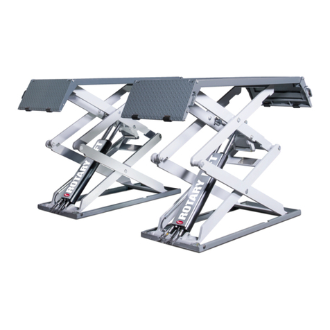
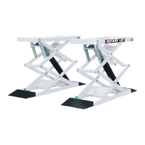
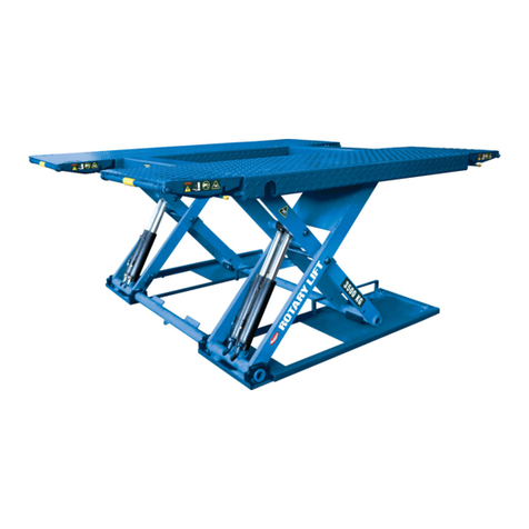
Rotary 100 Series User manual

XS30N-SMS
Rev.B 17/03/2020
© Rotary Lift, All rights reserved
O
P
E
R
A
T
I
O
N
&
M
A
I
N
T
E
N
A
N
C
E
M
A
N
U
A
L
O
P
E
R
A
T
I
O
N
&
M
A
I
N
T
E
N
A
N
C
E
M
A
N
U
A
L
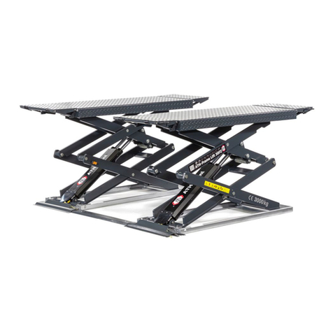
XS30N
(100 Series)
Scissor Lift
Installer: Please return this booklet to literature package and give to lift owner/operator.


EG-Konformitätserklärung
EC Declaration of Conformity
im Sinne der EG-Richtlinie 2006/42/EG über Maschinen (Anhang II A)
according to EC directive 2006/42/EC on machinery (Annex II A)
Name und Anschrift des Herstellers Name und Anschrift seines in der EU
Name and address of the manufacturer: niedergelassenen Bevollmächtigten
his authorised representative in EU
BlitzRotary GmbH BlitzRotary GmbH
Hüfinger Str.55 Hüfinger Str.55
78199 Bräunlingen, Germany 78199 Bräunlingen, Germany
Diese Erklärung bezieht sich nur auf die Maschine in dem Zustand, in dem sie in Verkehr gebracht wurde; vom
Endnutzer nachträglich angebrachte Teile und/oder nachträglich vorgenommene Eingriffe bleiben unberücksichtigt. Die
Erklärung verliert ihre Gültigkeit, wenn das Produkt ohne Zustimmung umgebaut oder verändert wird.
This declaration relates exclusively to the machinery in the state in which it was placed on the market, and excludes
components which are added and/or operations carried out subsequently by the final user. The declaration is no more
valid, if the product is modified without agreement.
Hiermit erklären wir, dass die nachstehend beschriebene Maschine
Herewith we declare, that the machinery described below
Produktbezeichnung / product denomination: Elektrohydraulische Scheren-
Hebebühne für Fahrzeuge
Electro-hydraulic scissor lift for vehicles
Serien- / Typenbezeichnung / model / type: XS30N
Tragfähigkeit 3000 kg / capacity 3000 kg
Maschinen-/Seriennummer / machinery / serial number: ……………….
Baujahr / Year of manufacture: 20……
allen einschlägigen Bestimmungen der Maschinenrichtlinie 2006/42/EG entspricht.
Die Maschine entspricht zusätzlich den Bestimmungen der Richtlinien 2014/30/EU über elektromagnetische
Verträglichkeit und 2014/35/EU über elektrische Betriebsmittel (Schutzziele wurden gemäß Anhang I, Nr. 1.5.1 der
Maschinenrichtlinie 2006/42/EG eingehalten).
is complying with all essential requirements of the Machinery Directive2006/42/EC.
In addition the machinery is in conformity with the EC Directives 2014/30/EC relating to electromagnetic
compatibility and 2014/35/EC relating to electrical equipment (Protection objectives have been met in accordance with
Annex I No. 1.5.1 of the Machinery Directive 2006/42/EC).
Angewandte harmonisierte Normen / Harmonised standards used
EN 1493: 2010 Fahrzeug-Hebebühnen / Vehicle lifts
EN ISO 12100:2010 Sicherheit von Maschinen - Grundbegriffe / Safety of Machinery- Basic concepts
EN 60204-1:2006/AC 2010 Elektrische Ausrüstung von Maschinen / Electrical equipment of machines
EN ISO 13850:2015 Sicherheit von Maschinen-Not-Halt / Safety of machinery – Emergency stop
Bevollmächtigter für die Zusammenstellung der relevanten technischen Unterlagen:
The person authorised to compile the relevant technical documentation:
Jürgen Maier; BlitzRotary GmbH, Hüfinger Str. 55; 78199 Bräunlingen, Germany
Ort / Place: Bräunlingen
Datum / Date:15.01.2020
Authorized Signature:
Title of signatory:
______________________
Doris Wochner-McVey
Geschäftsführer / Managing Director

1
Table of Contents
1. Packing, transport and storage.................................2
1.1 Packing............................................................................ 2
1.2 Lifting and handling.................................................... 2
1.3 Storage............................................................................ 2
1.4 Stacking the packs....................................................... 2
1.5 Opening.......................................................................... 2
2. Introduction ...................................................................3
2.1 Caution............................................................................ 3
2.2 Conservation of the manual..................................... 3
2.3 Laws ................................................................................. 3
3. Description of the machine........................................3
3.1 Structure ......................................................................... 3
3.2 Lifting unit ...................................................................... 4
3.3 Safety devices ............................................................... 4
3.4 Intend use ...................................................................... 4
3.5 Incorrect use, incorrect behavior............................ 4
3.6 Internal accident, health and safety, and
environmental information ................................................... 4
4. Technical specifications ..............................................5
4.1 Technical data............................................................... 5
4.2 Motor............................................................................... 5
4.3 Hydraulic control unit................................................. 5
4.4 Oil ..................................................................................... 5
5. Safety ...............................................................................6
5.1 Warning .......................................................................... 6
5.2 Safety devices ............................................................... 7
6. Installation......................................................................8
6.1 Warning .......................................................................... 8
6.2 Attention......................................................................... 8
7. Operating instructions ................................................ 9
7.1 Before Loading..............................................................9
7.2 Loading............................................................................9
7.3 Raise Lift (see figure11) ..............................................9
7.4 Before Lowering Lift ....................................................9
7.5 To Lower Lift (see Figure 11) ....................................9
7.6 Unloading .......................................................................9
8. Maintenance................................................................11
9. Commissioning ...........................................................12
9.1 Check Operation ....................................................... 12
9.2 Test the hydraulic system ....................................... 12
10. Disposal.....................................................................12
10.1 Environmental procedures for disposal ............. 12
10.2 Packaging .................................................................... 12
10.3 Oils, grease, and other chemical substances ... 12
10.4 Metals / Electronic waste........................................ 12
11. Trouble Shooting....................................................13
ANNEX
I. Hydraulic Circuit Diagram
II. Electric Wiring Diagram
III. Parts Break Down
IV. Mobile Kit
V. Spare Parts List

2
1. Packing, transport and
storage
ALL PACKING, LIFTING, HANDLING, TRANSPORT
AND UNPACKING OPERATIONS ARE TO BE
PERFORMED EXCLUSIVELY BY EXPERT PERSONNEL
WITH KNOWLEDGE OF THE LIFT AND THE CONTENTS
OF THIS MANUAL.
1.1 Packing
The lift is shipped assembled, resting on a
wooden platform in a single pack and sealed with
four straps. The total weight of the pack is
approximately 724 kg.
Figure 1 Handling with fork-lift truck
1.2 Lifting and handling
•
The wooden platforms can be lifted either with a
fork-lift truck (Figure 1) or with a crane or an
overhead travelling crane (Figure 2). In the case of
handling with a crane or overhead travelling crane,
the packs must always be loaded with at least 2
band.
•
NB. The chosen means must be suitable for
lifting and moving in safety, taking into
account dimensions, weight, center of
gravity, protrusions and fragile parts not to
be damaged.
1.3 Storage
The packs must always be kept in a covered and
sheltered place at a temperature between -25°C
and +55°C and must not be exposed to direct
sunlight.
1.4 Stacking the packs
•
This type of packing makes it possible to stack up
to 5 packs one on top of another in a store,
provided they are correctly arranged and secured
against falling.
•
The packs may be stacked only provided they are
not resting one directly on another, but plywood
and hardboard are inserted as shown in Figure 3.
•
Up to 5 packs can be stacked in the bodies of
lorries or in containers, provided they are well
strapped down and secured against falling.
1.5 Opening
When the wooden pack arrives, check that the
machine has not been damaged during transport
and that all parts listed are present.
The wooden pack must be opened using all
possible precautionary measures to avoid damaging
the machine or its parts.
1
2
3

3
2. Introduction
2.1 Caution
This manual has been written for the workshop
personnel assigned to using the lift (operator) and
for the engineer assigned to routine maintenance
(maintenance engineer). Therefore, before doing
anything with the lift and/or its packing, it is
necessary to read the entire manual carefully, as it
contains important information for:
•
THE SAFETY OF THE PERSONS assigned to its use
and routine maintenance.
•
THE SAFETY OF THE LIFT.
•
THE SAFETY OF THE LIFTED VEHICLES.
2.2 Conservation of the manual
The manual is an integral part of the lift and
must always accompany it, also in the case of sale.
It must always be kept close to the lift, in an easily
accessible place.
The operator and the maintenance engineer
must be able to find it and refer to it rapidly at any
time.
IN PARTICULAR, IT IS RECOMMENDED TO
READ CHAPTER 5 CAREFULLY AND
REPEATEDLY AS IT CONTAINS IMPORTANT
INFORMATION AND NOTICES RELATIVE TO
SAFETY.
2.3 Laws
The lifts have been designed and manufactured
in conformity with the following:
•
EN 1493:2010 Vehicle Lift
•
EN 60204-1:2006/AC:2010 Safety of machinery –
Electrical equipment of machines - Part 1: General
requirements
•
EN ISO 12100:2010 Safety of machinery - General
principles for design - Risk assessment and risk
reduction
•
EN 61000-6-2:2005+AC:2005 Electromagnetic
compatibility (EMC) Part 6-2: Generic standards —
Immunity for industrial environments
•
EN 61000-6-4:2007/A1:2011 Electromagnetic
compatibility (EMC) — Part 6-4: Generic standards —
Emission standard for industrial environments
3. Description of the machine
The electro-hydraulic lift, is a fixed
installation; this means that it is anchored to the
ground and designed and built for lifting and
positioning automobiles at a certain height off the
ground.
The lift is driven by an electro-hydraulic operating
system.
The lift consists of the following main parts:
• fixed structure (base);
• mobile units (levers + lifting platforms);
• lift units (hydraulic cylinders and hydraulic unit);
• control box;
• safety devices.
Figure 4 illustrates the various parts making up the
lift.
3.1 Structure
It is composed of a base (1) made of welded
steel plates, two platforms (2), four ramps (3)
and two pairs of leg weldment (4).
The base has holes for fixing to the ground by
means of optional anchor bolts. Inside the base
there are holes for the attachment of the lifting
legs. The platforms and legs are connected at the
ends by means of shafts and connected to the
base by means of special plastic supports. The
ramps are connected to the platform by means of
special shafts.
4
2
3
1
4
5

4
3.2 Lifting unit
It is composed of four hydraulic cylinders
connected by rigid and flexibles tubes.
The lifting unit is controlled by an electric
panel placed on an electric cabinet (5) containing
the hydraulic unit.
3.3 Safety devices
The safety devices are composed of:
•
double, hydraulic circuit
•
two safety solenoid valves
•
flow control valve adjusts descent speed
•
automatically activated micros witch stops
descent travel thus acting as foot guard
•
Flow control valve just in case the hose broken
3.4 Intend use
The scissor lift may only be used:
•
In indoor areas for lifting unoccupied motor
vehicles.
•
For lifting vehicles with a max. load capacity of
3000KG
•
If the weight is distributed correctly. By default,
the load should be centered in the direction of
motion. If the main load (e.g. engine) is however
at the front or the back, the following applies:
at front max. 3/5,
at back 2/5 of load or vice versa.
•
With correctly aligned, adjustable runways. The
vehicle must be approximately centered on the
two platforms.
•
In accordance with the technical data in
Chapter 4, in technically sound condition.
3.5 Incorrect use, incorrect behavior
Incorrect behavior presents a residual risk to
the life and health of the people working in the
lift area.
The manufacturer assumes no liability for
damage resulting from use other than the
intended purpose and from incorrect behavior.
The following is prohibited:
Figure 5
Climbing onto or riding on the scissor lift or
the load.
Lifting when there are people in the vehicle.
Lifting/lowering when people or animals are
in the danger zone, in particular below the
lift.
Jerky lifting or lowering. Do not cause the
lift to vibrate.
Throwing objects onto or under the lift.
Lifting a vehicle at the incorrect pick-up
points.
Lifting a load on only one platform of the lift.
Lifting vehicles containing hazardous goods.
Operating outdoors or in workshops at risk
from fire or explosion.
Washing cars on the post lift.
Modifications of any kind
3.6 Internal accident, health and
safety, and environmental information
This operating manual does not include the
operating instructions which need to be drafted
by the user of the scissor lift.
The internal operating instructions regulate
actions within the company for the prevention of
accidents, and risks to health & safety and the
environment.
These also include actions in the case of an
emergency, first aid measures etc.
5
BQ-144
1800
KG
1200
KG
Maximum Axle Load Distribution
No anchors ,prohibited distribution
Heavy
End Light
End

5
6
4. Technical specifications
4.1 Technical data
Operation.........................................electro-hydraulic
Carrying Capacity.............................3000kg
Lift time............................................. 30sec.
Lowering time................................... 20sec.
Noisy level........................................<74 db
Weight..............................................530 kg. approx.
Working temperature........................+7°C / +38°C
Installation requirements: enclosed area.
4.2 Motor
Power................................................2.6 KW
Voltage..............................................230V/400V3ph
Frequency.........................................50/60 Hz
Poles.................................................4
Speed................................................1410/1680rpm
Insulation class..................................F
Absorption........................................15.1/8.7A-50Hz
Service..............................................S3 10Min
4.3 Hydraulic control unit
Type...............................................Gear pump
Displacement................................. 8 cm /round
Peak pressure................................140 bar
Relief valve ....................................145 bar
4.4 Oil
Use Dexron III ATF, or hydraulic fluid that meets
ISO32 specifications. Remove fill breather cap and
add ten quarts of fluid. Turn power to on and ensure
the disconnect switch and emergency stop buttons
are in the "ON" position.
mm(without load)
990mm(with full load)
1000
<
<
3
11.1/6.4A-60Hz

6
5. Safety
5.1 Warning
Read this chapter carefully and completely since
important information for the safety of the operator
or others in case of improper use of the lift is
included.
FAILURE TO COMPLY WITH THESE
REGULATIONS CAN CAUSE SERIOUS INJURY
TO PERSONS, AND IRREPERABLE DAMAGE TO
THE LIFT AND THE VEHICLE BEIN LIFTED.
1 - Daily inspect your lift. Never operate if it
malfunctions or if it has broken or damaged parts.
Use only qualified lift service personnel and genuine
Rotary parts to make repairs.
2 - During lifting or lowering operations, the car
lift must be operated only from the operator’s
control site, as shown in the picture 4.
3 - Stopping or passing within the danger area
when the lift is working or already lifted is strictly
forbidden. Working personnel only is allowed to
stay near the lift.
4 - The operator must make sure the danger area
is empty before lifting or lowering the lift.
5 - Never use the machine without protection or
when the safety devices are out.
6- Always use the rubber pads when lifting a
vehicle, observing the proper support points
specified by the vehicle’s manufacturer. (see
chapter 7)
7
7 - To prevent the vehicle from falling make sure
it is properly placed on the lift.
8 - Getting on the vehicle and/or starting the
engine during lifting is strictly forbidden.
9 - Never leave objects and/or obstructions under
the vehicle during the lowering phase.
10 - Always keep area around lift free of tools,
debris, grease and oil to avoid the risk of slipping.
11 - Always keep platforms and ramps clean.
12 - Never use water steam varnish solvent jets
in the car lift area, and particularly next to the
control box.
13 - Proper lighting is extremely important.
Make sure all areas to the car lift are well and
uniformly lightened, according to the laws of the
country where the lift is installed.
14 - Climbing on the platforms when lifting the
vehicle or when the same has been already lifted is
strictly forbidden.
15 - Any use of the car lift other than what
herein specified can cause serious accidents to the
operator as well as to the people in close proximity.
16 - Never exceed the maximum carrying
capacity of 3000 kg when using the car lifts.
17 - Replace all control warnings, or safety
related decals on the lift when unable to read or
missing.
18 - Normal operating temperature range is 7°
C (45°F) to 38° (100° F).

7
5.2 Safety devices
1.Buzzer Acoustic alarm. Sounds: When
lowering the main lift<120mm (foot protection)
2.Lockable main switch
"ON" setting: Scissor lift ready for use.
"OFF" setting: Scissor lift out of use.
The mains voltage is still present inside the
control box. Switching off(OFF) immediately stops
any movement of the post lift (=emergency stop)
3.Overflow valve The overflow valve is factory
set to ca.145 bar. Prevents an overload lifting to
protect the hydraulic power unit from being
damaged.
4.Low limit switch on the scissor leg with
control unit Deactivates the lowering process at a
lift height of 120mm (foot protection, otherwise a
crushing or shearing hazard exists).
8
9
10

8
6. Installation
6.1 Warning
Unpack the goods and check for possible
damage before installing the car lift.
INSTALLATION REQUIREMENTS
The car lift must be installed according to the
specified safety distances from walls, columns,
other equipment, etc. The minimum distance from
walls must be 1000 mm at least, taking into
consideration the necessary space to work easily.
Further space for the control site and for possible
runways in case of emergency is also necessary.
The room must be previously arranged for the
power supply.
The car lift can be placed on a horizontal
concrete floor with concrete quality C20/C25 and
a minimum thickness of 150 mm.
•
Place the car lift as required following the
instructions above indicated.
•
Connect hydraulic hoses A and B and the
drain hose E to the power pack in the control
box (page 16).
•
Use Dexron III ATF, or hydraulic fluid that
meets ISO32 specific cations into the tank.
•
Then carry out electrical connection (see.
Diagrams on pages 17 )
ATTENTION!
Skilled personnel only are allowed
to perform this operation.
ATTENTION!
The installation must comply with
the regulations in force and must be equipped with
relevant fuses (see electrical installation).
If you have ordered the anchor bolts. Keeping the
platform in the highest position, drill the floor with
a helical bit having a diam. The size and depth of the
hole depends on the type of anchor bolt. Clean the
holes,
insert the optional anchor bolts and then
tighten with a torque wrench of 40 Nm.
6.2 Attention
In case of using the platform in a definite place
of the workshop, it can be chosen to fixed to the
floor with optional anchor bolts or not fixed,
according to instructions contained in this manual.
(figure 11)
In case of moving the scissor lift to different
places by optional mobile kit, the lift can be used
according to the following restrictions:
•
Place it on horizontal floor having proper
resistance.
•
Drive the vehicle on the cylinder opposite side
(see figure 12)
11
12
13
Maximum Axle Load Distribution
Heavy End
No anchors,prohibited distribution
Light End
1200 1800
BQ-122
Do Not lower lift to fully closed
when vehicle wheels are removed.
Die Hebebühne nicht zu weit
absenken,wenn die Räder
demontiert sind.

9
7. Operating instructions
WARNING
To avoid personal injury and/or property damage,
permit only trained personnel to operate lift. After
reviewing these instructions, get familiar with lift
controls by running the lift through a few cycles
before loading vehicle on lift.
ATTENTION
Always lift the vehicle using all four rubber pads.
Never raise just one end, one corner, or one side.
7.1 Before Loading
Inspect lift to assure it is in good operation
condition.
WARNING:
If lift is not operating properly, do
not use until adjustments or repairs are made by a
qualified lift service technician.
WARNING:
Keep hand and feet clear of linkages
while the lift is being raised or lowered.
WARNING:
Ensure overhead clearance is
provided to raise vehicles to desired height.
7.2 Loading
WARNING Before attempting to lift vehicle be
sure that:
• Assure lift is fully lowered before lifting.
• Vehicle is positioned over pads as shown in
figure 16.
• Vehicle body is strong enough to support its
weight and has not been weakened by modification
of corrosion.
• Use front ramp for vehicle support as
necessary to reach front lift points.
• If pickup points can still not be reached, use
both front and rear ramps for vehicle support.
• Use front ramp for vehicle support as
necessary to reach front lift points.
• If pickup points can still not be reached, use
both front and rear ramps for vehicle support.
• The field of motion of the load and of the load
carrying devices shall be free of obstructions
• Use auxiliary rubber blocks to create clearance
between vehicle chassis and lift pad.
• Auxiliary rubber blocks/pads are in secure
contact with vehicle manufacture's recommended
lift points.
• Vehicle is stable on lift; neither front nor tail
heavy.
7.3
Raise Lift (see figure15)
• Actuate RAISE BUTTON.
• Raise vehicle until tires clear the floor.
• STOP: Check pads for secure contact with
vehicle.
• Shake car moderately at front or rear bumper.
• Continue to raise to desired height ONLY if
vehicle is secure on lift If necessary, lower lift and
reposition using vehicle manufacture's
recommended pick-up points.
7.4 Before Lowering Lift
• Remove all obstacles from under vehicle and
lift.
• Assure personnel are not in lift area.
WARNING Observe warning decals,
(Figure 14)
7.5 To Lower Lift (see Figure 15)
• Remain clear of lift.
• Actuate the RAISE BUTTON for one second.
• Actuate the LOWER BUTTON to lower lift
while keeping feet clear.
7.6 Unloading
• Assure lift is fully lowered.
• Remove any rubber blocks used when raising
the vehicle.
• Carefully remove vehicle from lift area.
14

10
15
16
1. Power Switch
2. Buzzer
3. Raise Button
4. Lower Button
Fig. 3
Small Vehicle
FrontFrontFront
Large Vehicle
Midsize Vehicle
Fig. 2

11
8. Maintenance
WARNING
If you are not completely familiar
with automotive lift maintenance procedures STOP:
Contact factory for instructions.
To Avoid Personal Injury, permit only qualified
lift service personnel to perform maintenance on
this equipment.
Use only original equipment manufacturer
approved replacement parts for repairs.
• Always keep all bolts and nuts tight. Check
periodically.
• Always raise lift when cleaning floor area.
• Always keep lift clean. Keep bottom weldment
dry and free from corrosives such as salt and
cleaning fluids.
• Daily: Inspect rubber blocks for damage or
excessive wear. Replace as required with genuine
Rotary parts.
• Weekly: Inspect all lift parts for signs of
damage due to overloading and rough handling.
• Weekly: Empty water and refill oil as needed
for filter regulator lubricants.
• Monthly: Lightly grease sliding surfaces and
top cylinder clevis pin with all-purpose grease.
• Semi-Annually: Check fluid level of lift power
unit while lift is fully lowered. Refill if required per
fill line on tank. If fluid is required, inspect all hoses
and seals. Repair or replace as required.
• Semi-Annually: Check anchor bolts to ensure
they are torqued to 25ft.lbs.
• If lift stops short of full rise or chatters, check
fluid level and purge both cylinders per lift
installation instructions.
• Replace all CAUTION, WARNING, or SAFETY
related decals on the lift if unable to read or missing.
Reorder labels from Rotary Lift.
• Semi-Annually: If you have ordered the anchor
bolts. Check anchor bolts to ensure they are
torqued to 60Nm.
• If lift stops short of full rise or chatters, check
fluid level and purge both cylinders per lift
installation instructions.
• Replace all CAUTION, WARNING, or SAFETY
related decals on the lift if unable to read or missing.
Reorder labels from Rotary Lift.

12
9. Commissioning
9.1 Check Operation
Operate lift and assure that push button raises
lift when pushed and stops lift when released.
Check disconnect switches for cutting power to
pushbuttons. Also check that limit switch stops lift
from lowering when actuated.
Lubricate the surface of slide between the top
platform and base frame before commissioning. It
can be applied by brushing. This can significantly
increase the service life of the lift.
9.2 Test the hydraulic system
1.Set the main switch to ON.
2.Move the unloaded lift to full rise and the
bottom position several times using the Up and
Down buttons. This will completely remove any air
pockets in the hydraulic system.
3.Press up button to raise lift to full rise and
keep motor running for 5 seconds. Stop and check
all hoses connections. Tighten or reseal if required.
4.Carry out a visual inspection of the hydraulic
and pneumatic system. In doing so, check all lines,
especially the couplings. No leaks must be found.
5.Lower the lift completely and check the
hydraulic oil level. This must also correspond to the
maximum level.
6.Finally check that the hydraulic components
are fitted securely.
10.Disposal
10.1 Environmental procedures for
disposal
Prevent environmental hazards.
Avoid contact with or inhalation of toxic sub-
stances such as hydraulic fluid
Oils and lubricants are water pollutants under
the terms of the Water Management Act WGH.
Always dispose of these in an environmentally
friendly manner in compliance with the
regulations which apply in your country.
Hydraulic oil-based on mineral oil is a water
pollutant and is combustible. Refer to the
relevant safety data sheet for disposal.
Provide suitable oil drain pans and oil
absorbents to drain the oil.
Ensure that no hydraulic oil, lubricants, or
cleaning materials contaminate the soil or
wash away into the drainage system.
10.2 Packaging
Do not dispose of with domestic waste! The
packaging contains some recyclable material which
must not disposed of with domestic waste.
Dispose of packaging materials in compliance
with local regulations.
10.3 Oils, grease, and other
chemical substances
When working with oil, grease and other
chemical substances, comply with the
environmental regulations which apply to the
relevant product.
Dispose of oil, grease and other chemical
substances in compliance with the environmental
regulations which apply in your country.
10.4 Metals / Electronic waste
This must always be properly disposed of by a
certified company.
Dispose of used electrical and electronoc
devices ,including cables,accessories
and batteries,separately from household
waste.

13
11. Trouble Shooting
Trouble
Electric motor does not run.
Electric motor runs but will not
raise lift.
Oil Blowing Out Fill-Breather
Cap
Lift Fails to Raise When Pushing
Raise Button
The lowering button is pressed
but the lift does not lower.
Cause
1.Blown fuse or tripped circuit
breaker.
2.Incorrect voltage to motor.
3.Damaged wiring connections.
4.The motor thermic switch is
activated from overheating.
1.Motor runs in reverse rotation.
2.Load too heavy.
3.Low fluid level.
4.Suction tube is clogged.
1.Oil Leak/Pump Failure.
2.Incoming Motor Voltage
Incorrect.
3.Vehicle Weight and Balance Not
Within Lift Capacity.
1.Raise button defective.
2.Vehicle weight and balance not
within lift capacity
3.Motor rotation incorrect.
4.Incoming motor voltage incorrect
or insufficient
5.Loose or damaged wiring
6.Blown fuse.
1.Obstacles blocking the lowering
phase.
2.Switch is off or power supply is
interrupted.
Remedy
1.Replace blown fuse or reset
circuit breaker.
2.Supply correct voltage to motor.
3.Repair and insulate all
connections.
4.Wait for 10 minutes and try
starting again; then, using a
tester make sure contact is
closed again.
1.Switch the phase and make sure
motor turns in the direction
indicated by the arrow.
2.Check vehicle capacity.
3.Fill tank with Dexron III ATF or
ISO32.
4. Check and clean.
1.External oil leak-locate and repair
leak. Internal oil leak-have
hydraulic system serviced by an
authorized service representative.
2.Supply correct voltage to motor,
contact your local service
authority.
3.Use lift only to rated capacity.
1.Replace raise button.
2.Use lift only at rated load.
3.Switch the phase and make sure
motor turns in the direction.
4.Supply correct voltage to motor,
contact your local service
authority.
5.Inspect and repair loose or
damaged wiring.
6.Check for blown fuse.
1.Remove the obstacles blocking
the lowering phase.
2.Check and supply power to lift.

14
Annex
Scissor lift
XS30N
Series 100

15
I. Hydraulic circuit diagram
HYDRAULIC SYSTEM DIAGRAM
1 Tank
2 Filter
3 Pump
4 Motor
5 Relief Valve
6 Check Valve
7 Velocity Valve
8 Flow Control Valve
9 Solenoid Valve
10 Solenoid Valve
11 Flow Control Valve

16
HYDRAULIC DIAGRAM CONNECTION
E

17
I I . Electric wiring diagram
QS1 Power switch SB1 Raise button
FU1 Fuse 16A SB2 Lower button
FU2 Fuse 2A HZ1 Buzzer
TR1 Transformer EV1 Solenoid valve
KM1 Contactor EV2 Solenoid valve
KA1 Intermediate relay SQ1 Proximity switch (Low)
FU3 Fuse 1A FU4 Fuse 3A
Other manuals for 100 Series
3
This manual suits for next models
1
Table of contents
Other Rotary Scissor Lift manuals

Rotary
Rotary 300 Series Manual

Rotary
Rotary GEMINI GLP 30 User manual

Rotary
Rotary GLP99SM User manual

Rotary
Rotary MIRACH 40 User manual

Rotary
Rotary GLP 35 User manual

Rotary
Rotary 000 Series Manual

Rotary
Rotary 000 Series User manual

Rotary
Rotary GLP 35 User manual

Rotary
Rotary GEMINI GLP 30 User manual

Rotary
Rotary SM40 Manual