RUD LRBS-FIX User manual

1
LRBS-FIX
RUD Ketten
Rieger & Dietz GmbH u. Co. KG
73428 Aalen
Tel. +49 7361 504-1370
Fax +49 7361 504-1460
www.rud.com
RUD-Art.-Nr.: 7901036 - EN / 04.021
> LRBS-FIX <
Lashing point
Load Ring weldable
Safety instructions
This safety instruction/declaration has to be kept on le
for the whole lifetime of the product.
Translation of the original safety instruction
> LRBS-FIX <
Lashing point
Load Ring weldable
Herstellererklärung
Hiermit erklären wir (unterstützt durch die Zertizie-
rung nach ISO 9001), dass die nachfolgend bezeich-
nete Ausrüstung aufgrund ihrer Konzipierung und
Bauart, sowie der von uns in Verkehr gebrachten
Ausführung, den einschlägigen grundlegenden Si-
cherheits- und Gesundheitsanforderungen der Eu-
ropäischen Union entspricht. Bei einer nicht mit uns
abgestimmten Änderung der Ausrüstung verliert diese
Erklärung ihre Gültigkeit. Weiterhin verliert diese
Erklärung ihre Gültigkeit, wenn die Ausrüstung nicht
entsprechend den in der Betriebsanleitung aufge-
zeigten bestimmungsmäßigen Fällen eingesetzt wird.
Hinweis: Beim Zurrpunkt angewendete harmonisierte
Normen DIN EN ISO 12100 T1 und T2 sowie in An-
lehnung an EN 1677.
Bezeichnung der Ausrüstung:
Zurrpunkt
Type: Ringbock schweißbar
Herstellerzeichen:
Declaration of the manufacturer
We hereby declare (supported by ISO 9001 certi-
fication), that the following described equipment
based on the concept and design as well as the by
us manufactured type corresponds to the current
valid Health- and Safety Requirements of the EU.
This declarations becomes invalid in case of any
modications not agreed upon with us. Furthermore
this declaration becomes invalid if the equipment is
not used according to this prescription.
Hint: Utilized harmonized standards for this Lashing
Point DIN EN 12 100 T1 and T2 as well as EN 1677.
Designation of the equipment:
Lashing point
Type: Load Ring weldable
Manufacturer‘s sign:
EN

2LRBS-FIX
Before initial usage of the RUD LRBS-
FIX, please read carefully the safety
instructions. Make sure that you have
understood all subjected matters.
Non-observance can lead to serious per-
sonal injuries and material damage and
eliminates warranty.
1 Safety instructions
ATTENTION
Wrong positioned or damaged weld-on
lashing points as well as improper use can
lead to injuries of persons and damage at
property, when load falls down.
Please check all lashing points carefully
before every usage.
• Keep all body parts like ngers, hands, arms, etc. out
of the hazardous area during the lashing operation.
• RUD Lashing points LRBS-FIX must only be used
by instructed and competent persons considering
DGUV 109-017 (BGR 500), and outside Germany
noticing the country specic statutory regulations.
• Attention: When suspension ring pivots there is a
risk of pinching.
• The stated LC (Lashing Capacity) at the LRBS-FIX
must not be exceeded.
• Any technical modications at the LRBS-FIX are
prohibited.
• Keep persons out of the hazardous area.
• Damaged or worn LRBS-FIX must no longer be
used.
2 Intended use of the LRBS-FIX
RUD Lashing points LRBS-FIX must only be used to
attach lashing means.
The lashing points must not protrude in rest position
over the loading platform level.
In general, lashing points must not be used for lifting!
RUD Lashing points must only be used in the hereby
specied case of operation.
3 Assembly- and instruction manual
3.1 General information
• Capability of temperature usage:
As of 07/2019: RUD Lashing points LRBS-FIX are
suitable for the temperature range from -40°C up
to 400°C.
Up to 07/2019: RUD Lashing points LRBS-FIX are
suitable for the temperature range from -20°C up
to 400°C.
For the use within the following temperature range,
the WLL must be reduced by the following factors:
-40°C / -20°C up to 200°C no reduction
200°C up to 300°C: by -10 % and
300°C up to 400°C: by -25 %
Temperatures exceeding 400°C are prohibited
In the unloaded state, LRBS-FIX Lashing points
together with the load can be stress relieved by
heat treating (e.g. welded construction) once.
Temperature: < 600°C (one hour maximum).
After stress-relieving heat treatment (< 600°C),
however,the spring force is no longer usable.
• RUD Lashing points LRBS-FIX must not be used
with aggressive chemicals such as acids, alkaline
solutions and their vapours.
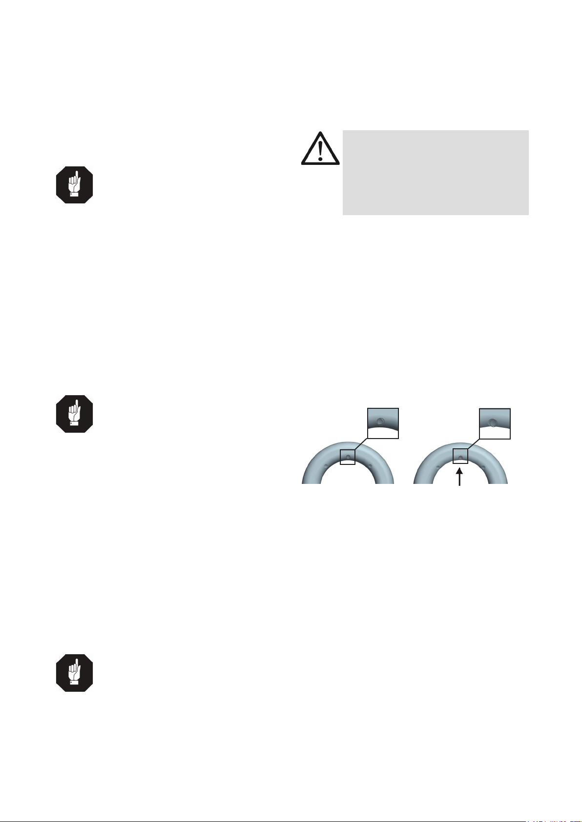
• Please mark mounting position of Lashing point
with a coloured contrast paint for better visibility.
• LRBS-FIX includes a protected positioned clam-
ping spring, inside the weld-on block. The spring
holds the weld-on blocks together with the ring
and creates at the same time a radial clamping
function.
• RUD Lashing points LRBS-FIX are clearly mar-
ked at the suspension ring with the permissible
Lashing capacity „LC“ in daN.
• LRBS-FIX will be delivered as a complete assem-
bled unit.
3.2 Hints for the assembly
Basically essential:
• The material construction to which the lashing point
will be attached should be of adequate strength to
withstand forces during lashing without deformation.
The weld-on material must be suitable for welding
and the contact areas must be free from dirt, oil,
colour, ect.
The material of the forged welding block is:
S355J2+N (1.0577+N (St52-3))
• The position of the lashing points must be carried
out in regard to the lashing means in such a way
that unintended movement like turning or ipping
of the load will be avoided.
INHALT
1 Safety instructions 2
2 Intended use of the LRBS-FIX 2
3 Assembly- and instruction manual 2
3.1 General information ..................................................2
3.2 Hints for the assembly ..............................................2
3.3 Hints for the welding .................................................3
3.4 User instructions.......................................................3
4 Inspection / Repair / Disposal 4
4.1 Hints for the regularly inspection ..............................4
4.2 Inspection criteria for the regularly
examination carried out by the operator ...................4
4.3 Additional inspection criteria for the
competent person resp. auditor................................4
4.4 Disposal....................................................................4
5 Tables/Overview 4

3
LRBS-FIX
• Determine number and position of the lashing
points at vehicles according to EN 12640 resp. DIN
75410 (for RoRo-transportation acc. to EN 29367),
unless the vehicles are not determined due to their
design and construction for transporting specic
goods with special requirements in regard of load
securing.
• Position lashing points as much as possible at the
outside width of the loading platform.
HINT
The lashing points must not protrude in rest
position over the loading platform level.
• Determine the necessary lashing capacity of each
lashing point acc. to EN 12195-1”Load securing
devices on road vehicles” - “Calculation of lashing
forces” and VDI 2700 ”Load securing of road ve-
hicles.”
• Check nally the correct assembly (see chapter
4 Inspection / Repair / Disposal).
3.3 Hints for the welding
The welding should only be carried out according to
DIN EN ISO 9606-1 or AWS Standards by an autho-
rized and certied welder.
Verication of the used weld-on material must be
checked with the supplier of the welding electrodes.
HINT
• Never weld at the quentched and
tempered ring!
• Weld all seams at the same
temperature.
1. Check before initial appending of the LRBS-Fix,
the position of the weld-on blocks to each other,
that means the base area must be at the same
level.
2. Append weld-on blocks.
3. Check function of the ring. The ring must be able
to pivot 180°. If necessary please correct.
4. Remove any welding mistakes and dirt at the root
weld before applying the cover weld seams.
5. Weld blocks on (HY-weld circumferential).
Choose type of weld seam and size according to
picture 2 and chart 2.
6. Please check by a competent person after welding
the ongoing usage of the weld-on lashing point
(see chapter 4 Inspection / Repair / Disposal)
HINT
By the position of the weld-seam (HY-weld
circumferential) the following requirements
will be observed: DIN 18800 steel con-
structions requires: at outdoor buildings or
when strong corrosion must be expected
weld seams must be carried out as conti-
nuous llet weld seams.
3.4 User instructions
• Check frequently and before each initial operation
the whole lashing point in regard of linger ability
as a lashing mean, regarding corrosion, wear,
deformation etc. (see chapter 4 Inspection / Repair
/ Disposal).
ATTENTION
Wrong positioned or damaged weld-on
lashing points as well as improper use can
lead to injuries of persons and damage at
property, when load falls down.
Please check all lashing points carefully
before every usage.
• RUD components have been designed as per DIN
EN 818 and DIN EN 1677 for a dynamic load of
20,000 load cycles.
• Observe and be aware that multiple load cycles
can occur during a lashing operation.
• Observe the risk of product damage caused by
high dynamical inuences at high load cycle
numbers.
• BG/DGUV Germany’s employer insurance asso-
ciation recommends: At high dynamical loading
with a high number of load cycles (permanent
use), the stress at WLL acc. to FEM class 1Bm
(M3 acc. to DIN EN 818-7) must be reduced.
Use a lashing point with a higher LC.
• Please check carefully the wear indicator markings
of the weld-on lashing point (see Pic. 1):
Usage permitted:
no wear marks
visible
Use prohibited:
Replacement criteria rea-
ched. Material all the
way down to the
wear lenses has gone.
Pic. 1: Wear indicators
• Please note that the lashing mean must be free
moveable in the LRBS-FIX. When lashing means
(f.e. lashing chain) are hinged or unhinged, no
pinching, shearing or joint spots must occure du-
ring the handling.
• Avoid damage of lashing means resulting from
sharp edges.
• Lashing points must not be used for lifting loads.

4LRBS-FIX
4 Inspection / Repair / Disposal
4.1 Hints for the regularly inspection
The operator has to determine and dictate the neces-
sary inspection periods and the deadlines by a risk
assessment (see sections 4.2 and 4.3).
The persisting appropriateness of the lashing point
must be checked by a competent person (auditor) at
least once per year.
Depending on the conditions of use e.g. frequent use,
increased wear or corrosion, it may be necessary to
carry out inspections at shorter intervals than once per
year. A verication is also required following damage
and after special events.
The operator must specify the test cycles.
4.2 Inspection criteria for the regularly
examination carried out by the operator
• Completeness of the lashing point
• Complete and readable marking of Lashing Capa-
city as well as manufacturer sign.
• Deformation at load bearing components like base
body and Ring.
• Mechanical damage, like strong notches, especial-
ly in areas where tensile stress occurs.
4.3 Additional inspection criteria for the
competent person resp. auditor
• Reduction of cross-section due to wear >10 %
• Evidence of corrosion (pitting)
• Additional inspections may be necessary depen-
ding on the result of the risk assessment (e.g.
incipient cracks at load bearing parts/weld seam).
4.4 Disposal
Dispose worn out components / attachments or
packaging according to the local waste removal
requirements.
5 Tables/Overview
Type size length Volumen
LRBS-FIX 8000 HY 3 2 x 154 mm ca. 1,4 cm³
LRBS-FIX 13400 HY 5 2 x 214 mm ca. 5,35 cm³
LRBS-FIX 20000 HY 6 2 x 252 mm ca. 9 cm³
LRBS-FIX 32000 HY 9 2 x 341 mm ca. 27 cm³
Table 1: Weld seam (weld-on block)
HY weld-seam circumferntial
Pic. 2: HY-weld seam
Pic. 3: Lashing Ring is integrated in the design

5
LRBS-FIX
Europe, USA, Asia, Australia, Africa
Baustähle, niedrig legierte Stähle EN 10025,
Mild steels, low alloyed steel EN 10025
MIG / MAG (135)
Gas shilded wire welding
(135)
DIN EN ISO 14341: G4Si1 (G3Si1)
Z.B. PEGO G4Si1
E-Hand Gleichstrom
(111, =)
Stick Electrode
direct current
DIN EN ISO 2560-A: E 42 6 B 3 2 H10
DIN EN ISO 2560-A: E 38 2 B 1 2 H10
z.B. PEGO B Spezial*/
PEGO BR Spezial*
E-Hand
(Wechselstrom 111, ~)
Stick Electrode
alternating current
DIN EN ISO 2560-A: E 38 2 RB 1 2
DIN EN ISO 2560-A: E 42 0 RC 1 1
z.B. PEGO RC 3 / PEGO RR B 7
Alternativ:
DIN EN ISO 3581: E 23 12 2 L R 3 2
z.B. PEGO 309 MoL
WIG (141)
TIG Tungsten arc welding
DIN EN ISO 636-A: W 3 Si 1 (W2 Si 1)
DIN EN ISO 636-A: W 2 Ni 2
z.B. PEGO WSG 2 / PEGO WSG2Ni2
Table 2: Welding procedure + Welding ller metals
Type
LRBS-FIX kompl.
LC
[daN]
A
[mm]
B
[mm]
C
[mm]
D
[mm]
E
[mm]
F
[mm]
T
[mm]
weight
[kg/pc.]
Ref. no
LRBS-FIX 8.000 8.000 60 14 39 48 132 69 74 0,93 7999303
LRBS-FIX 13.400 13.400 88 20 50 60 167 91 97 2,2 7999304
LRBS-FIX 20.000 20.000 100 22 60 65 191 100 108 3,7 7999305
LRBS-FIX 32.000 32.000 130 30 72 90 267 134 140 8,0 7999306
Table 3: Dimensioning LRBS-FIX complete Subject to technical alterations
Type
Lashing Ring
LC
[daN]
A
[mm]
B
[mm]
C
[mm]
D
[mm]
E
[mm]
F
[mm]
G
[mm]
T
[mm]
O
[mm]
Q
[mm]
weight
[kg/pc.]
Ref. no
Zurrlasche 8.000 8.000 107 14 69 48 17 18 76 63,5 19+0,5 77+1 0,38 7902251
Zurrlasche 13.400 13.400 134 20 91 60 23 23 100 82,5 25+0,5 101+1 0,96 7902252
Zurrlasche 20.000 20.000 152 22 100 65 28 29 105 92 30+0,5 106+1 1,46 7902331
Table 4: Dimensioning LRBS-FIX Lashing Ring Subject to technical alterations
HINT
Please note the corre-
sponding user hint in
regard of the welding
ller materials and the
drying requirements*.
Pic. 4: Dimensioning LRBS-FIX complete Pic. 5: Dimensioning Lashing Ring
Table of contents
Other RUD Automobile Accessories manuals

RUD
RUD easy2go Owner's manual

RUD
RUD CENTRAX V 4717999 User manual

RUD
RUD CENTRAX User manual

RUD
RUD VLBS-U-LT User manual

RUD
RUD CENTRAX User manual

RUD
RUD ARKTIS EASY 1 GO User manual

RUD
RUD RUDmatic Maxi Install guide

RUD
RUD RUDinnov8 Hybrid Install guide

RUD
RUD ARKTIS SCHNEEKETTEN T-POWER User manual

RUD
RUD CENTRAX User manual