Rupes RH323 User manual

Via Marconi, 3/A- Loc. Vermezzo
20071 Vermezzo con Zelo (MI) - ITALY
Tel +39 02 946941 - Fax +39 02 94941040
IT Levigatrici rotorbitali pneumatiche........................................................................................................... 2
EN Random-orbital pneumtic sanders............................................................................................................6
FR Ponceuses rotorbitales pneumatiques................................................................................................... 10
DE Pneumatische Exzenterschleifer............................................................................................................. 14
ES Lijadoras rotórbitales neumáticas.......................................................................................................... 18
NL Pneumatisch roterend excentrische schuurmachine........................................................................... 22
RU Пневматическиевращательно-орбитальныешлифовальныемашины ..................................... 26
AR .................................................................................................................................................................... 30
BG Пневматичниорбиталнишлайфмашини............................................................................................ 34
ZH 气动式转子砂光机气动式转子砂光机................................................................................................................................. 38
CS Pneumatické excentrické brusky............................................................................................................ 42
DA Pneumatiske roterende slibemaskiner................................................................................................... 46
ET Pneumaatilised ekstsentriklihvmasinad................................................................................................. 50
FI Paineilmakäyttöiset kehähiomakoneet................................................................................................... 54
EL Λειαντικάμηχανήματαπεριστροφικήςκίνησηςπεπιεσμένουαέρα[τριβεία].................................... 58
HU Levegősrotációscsiszoló....................................................................................................................... 62
HI - ............................................................................................................................ 66
LT Pneimatiskāsorbitālāsslīpmašīnas ....................................................................................................... 70
LV Pneumatinėsžiedinėsšlifavimostaklės................................................................................................. 74
PL Szlifierkioscylacyjnepneumatyczne...................................................................................................... 78
PT Lixadoras orbitais especiais pneumáticas............................................................................................. 82
RO Mașinideșlefuitpneumaticeroto-orbitale............................................................................................. 86
SK Pneumatickérotačnéorbitálnebrúsky................................................................................................... 90
SL Ekscentričnipnevmatskibrusilniki......................................................................................................... 94
SV Pneumatiska excenterslipmaskiner........................................................................................................ 98
RH323
RH323A
RH323T
RH326
RH326A
RH326T
RH329
RH329A
RH329T
RH353
RH353A
RH353T
RH356
RH356A
RH356T
RH359
RH359A
RH359T
ءاوﮭﻟا طﻐﺿﺑ لﻣﻌﺗ ﻟا ةراودﻟا ةرﻔﻧﺻﻟا ﺔﻧﯾﻛﺎﻣ

14
14
TECHNISCHE DATEN
ÜBERSETZUNG DES URSPRÜNGLICHEN BEDIENUNGSANLEITUNG
14
PIKTOGRAMM
Wichtige Sicherheitshinweise / Geräts folgendeAnweisungen
Lesen Sie vor Bedienung
Schutzbrille
Gehörschutz tragen
Tragen Sie eine Maske
Prüfzeichen
CU TR Qualitätskennzeichen
Durchmesser Durchmesser der Scheibe, Schleifteller, die Umlaufbahn
Leerlaufdrehzahl Geschwindigkeit dreht
Umdrehungen Geschwindigkeit
Pfeil Act in der durch den Pfeil angegebenen Richtung Richtung
RH223 - RH226 - RH229 RH253 - RH256 - RH259
Ø
no
.../min.
Einige der folgenden Symbole können am Werkzeug vorhanden sein. Bitte studieren und lernen, ihre Bedeutung. Die richtige Interpretation wird
die optimale Nutzung und sichere Werkzeug ermöglichen.
TECHNISCHE DATEN
Pneumatische Exzenterschleifer
Betriebsdruck [bar/PSI]
Luftverbrauch [l/min]
Umdrehungen n° [/min]
Ø Schwingkreis [mm]
Ø Schleifteller [mm]
Absaugvorrichtung
Gewicht [Kg]
RH323 RH353
6.2 / 90
340
0 - 11.000
3
125 150
NEIN
0.800
RH326 RH356
6.2 / 90
340
0 - 11.000
6
125 150
NEIN
0.800
RH329 RH359
6.2 / 90
340
0 - 11.000
9
125 150
NEIN
0.800
RH323 - RH326 - RH329 RH353 - RH356 - RH359

15
15
DATI TECNICI
RH223A - RH226A - RH229A RH253A - RH256A - RH259A
TECHNISCHE DATEN
Pneumatische Exzenterschleifer
Betriebsdruck [bar/PSI]
Luftverbrauch [l/min]
Umdrehungen n° [/min]
Ø Schwingkreis [mm]
Ø Schleifteller [mm]
Absaugvorrichtung
Gewicht [Kg]
RH323A RH353A
6.2 / 90
340
0 - 11.000
3
125 150
CENTRAL
0.800
RH326A RH356A
6.2 / 90
340
0 - 11.000
6
125 150
CENTRAL
0.800
RH329A RH359A
6.2 / 90
340
0 - 11.000
9
125 150
CENTRAL
0.800
Die genannten Gerätes dürfen nur zusammen mit einer passenden Staubabsaugung betrieben werden (kein Lieferbestandteil).
DATI TECNICI
RH223T - RH226T - RH229T RH253T - RH256T - RH259T
Die genannten Gerätes Dürfen nur zusammen passenden Staubabsaugung Betrieben Werden sie verbunden mit dem Filter
TECHNISCHE DATEN
Pneumatische Exzenterschleifer
Betriebsdruck [bar/PSI]
Luftverbrauch [l/min]
Umdrehungen n° [/min]
Ø Schwingkreis [mm]
Ø Schleifteller [mm]
Absaugvorrichtung
Gewicht [Kg]
RH323T RH353T
6.2 / 90
340
0 - 11.000
3
125 150
EIGENABSAUGUNG
0.800
RH326T RH356T
6.2 / 90
340
0 - 11.000
6
125 150
EIGENABSAUGUNG
0.800
RH329T RH359T
6.2 / 90
340
0 - 11.000
9
125 150
EIGENABSAUGUNG
0.800
RH323A - RH326A - RH329A RH353A - RH356A - RH359A
RH323T - RH326T - RH329T RH353T - RH356T - RH359T

16
ALLGEMEINE HINWEISE
Die Sicherheits- und Unfallverhütungsvorschriften sind im
beiliegenden Heft „HINWEISE ZUR SICHERHEIT" enthalten.
Das Heft ist integrierender Bestandteil der vorliegenden
Dokumentation; Diese BEDIENUNGSANLEITUNG enthält daher
nurZusatzinformationen,welchedenspezifischenEinsatzdieses
Geräts betreffen.
BESTIMMNGSGEMÄSSE VERWENDUNG
DiesesWerkzeugistfürden Einsatz alsSchleifmachinebestimmt.
Alle Sicherheitshinweise, die Anweisungen, die Abbildungen
und die technischen Daten beachten, die mit diesem Werkzeug
geliefert werden. Die mangelnde Beachtung aller unten aufgeführten
Anweisungen kann zu elektrischen Schlägen, Unfällen führen.
Von Vorgängen des Feinschleifens, Polierens, metallischen
Bürstens oder Schneidens wird mit diesem Werkzeug abgeraten.
Die Vorgänge, für diedas Werkzeug nichtvorgesehen ist, können eine
Gefahr darstellen und Personenschäden verursachen.
INFORMATIONEN SCHALLPEGEL/MITTLEREBESCHLEUNIGUNG
Der Schalldruckpegel (Geräuschentwicklung) und die mittlere
quadratischeBeschleunigungder Maschine, gemessen gemäß
EN ISO 15744 - EN ISO 28927.
Schalldruckpegel Messunsicherheit Schalleistungspegel
level[dB(A)] [dB(A)] level[dB(A)]
LpA K LwA
RH323-RH353 73 3 84
RH326-RH356 75 3 86
RH329-RH359 76 3 87
RH323A-RH353A 72 3 83
RH326A-RH356A 74 3 85
RH329A-RH359A 75 3 86
RH323T-RH353T 72 3 83
RH326T-RH356T 74 3 85
RH329T-RH359T 75 3 86
Vibrationspegel [m/s2]
3-Achsen Messunsicherheit 1-Achsen (*)
LpA K LwA
RH323-RH353 2,80 0,20 <2,50
RH326-RH356 3,00 0,30 2,60
RH329-RH359 3,20 0,35 2,80
RH323A-RH353A 2,80 0,20 <2,50
RH326A-RH356A 3,00 0,30 2,60
RH329A-RH359A 3,20 0,35 2,80
RH323T-RH353T 2,80 0,20 <2,50
RH326T-RH356T 3,00 0,30 2,60
RH329T-RH359T 3,20 0,35 2,80
(*) Schwingungswerte nach der alten EN ISO 8662-8.
Bei den gezeigten Pegelwerten handelt es sich um Vergleichswerte,
diezueinervorläugenEinschätzungdesRisikosfürdenBedienenden
während derArbeitszeit dienen. Für eine angemessene Einschätzung
der Arbeitszeit müssen die Zeiten berücksichtigt werden, in denen
sich das Gerät im Ruhezustand bendet oder ausgeschaltet ist.
Diese Werte wurden anhand der Haupteinsatzgebiete des Geräts
ermittelt. Wenn das Gerät für andere Aufgaben oder mit anderen
Zubehörprodukten verwendet wird oder keine regelmäßigen
Wartungsarbeiten durchgeführt werden, können diese Werte beim
Betrieb deutlich überschritten werden.
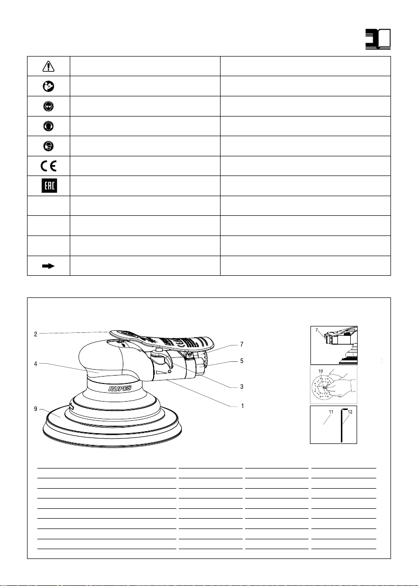
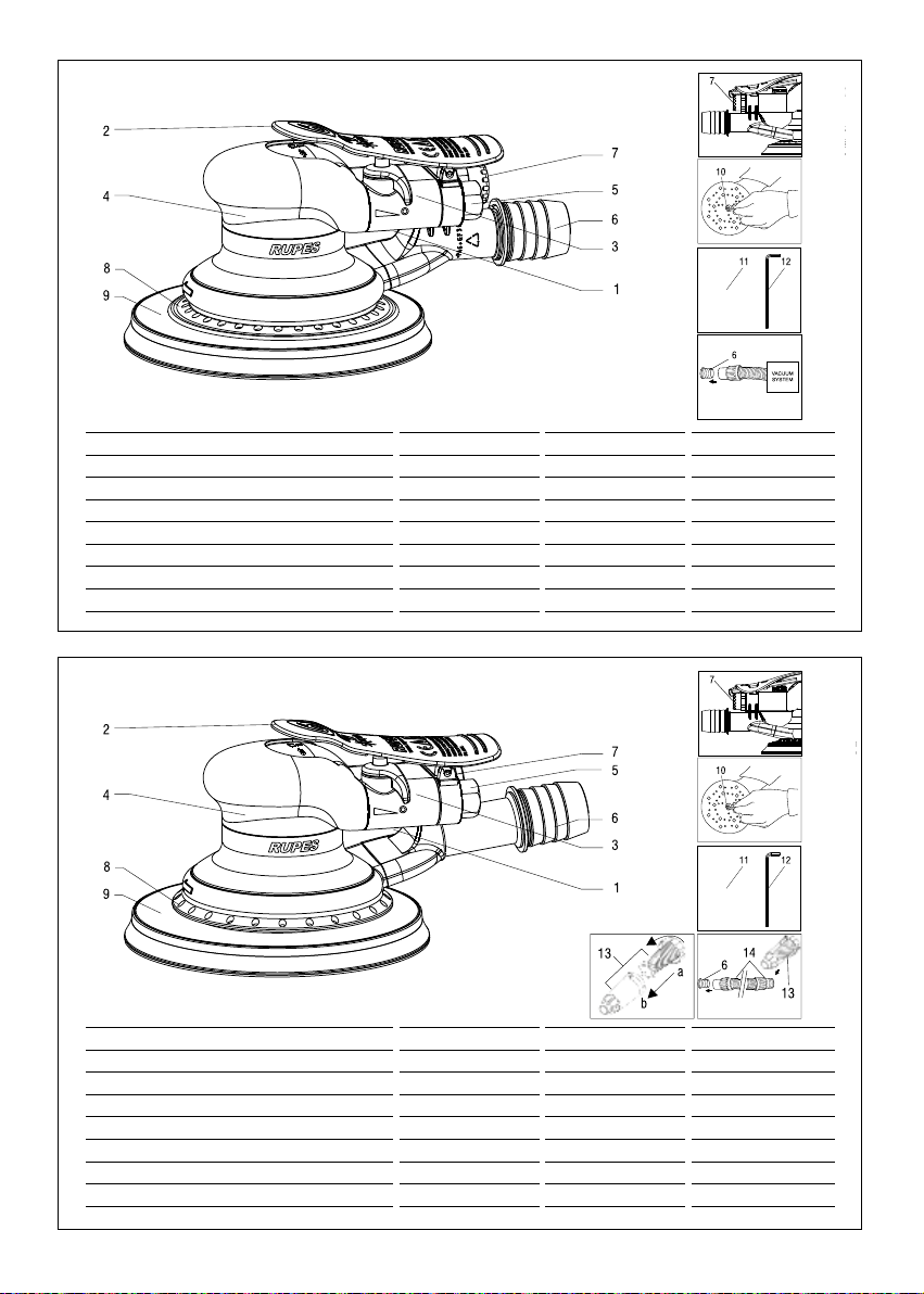
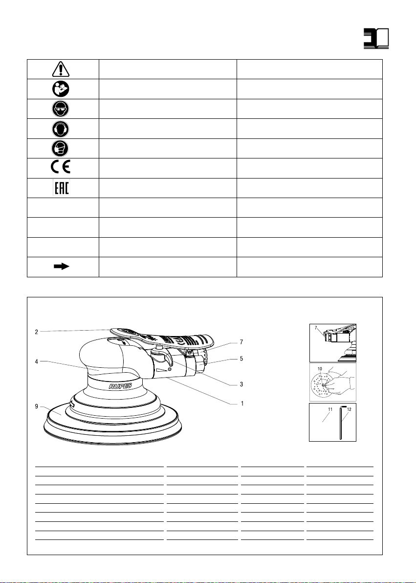
BABUTEILE DER MASCHINE
1 - Schild mit Geräte-Kenndaten
2 - Bedienhebel z. Einleitung der Druckluft
3 - Drehzahleinstellung
4 - Gerätegehäuse
5 - Druckluftanschluß
6 - Anschluß f. Absaugschlauch; Innenweite Ø 29/25 mm
(SERIES RH..A- RH..T)
7 - Schalldämpfer
8 - Absaughaube (SERIES RH..A- RH..T
9 - Schleifteller
10 - Schraube für Stützteller
11 - Schmieröl
12 - Innensechskantschlüssel
13 - Filtereinheit: Patrone (a) und Filterhalter (b) (RH..T SERIE)
14 - Rohr Staubabsaugung Betrieben (SERIE RH..T)
INBETRIEBNAHME
Vor einer Inbetriebnahme des Geräts sollten Sie sicherstellen:
- daßdie Verpackungunversehrt istund keineBeschädigungen durch
Transport bzw. Lagerung aufweist;
- ob die Druckluftaufbereitung und -zuleitung die in der Tabelle
sowie auf dem Geräteschild genannten Anforderungen erfüllt. Die
Kenndaten des Geräteschilds.
ZUSAMMENBAU DER MASCHINE
Das Druckluft-Kupplungsstück (nicht mitgeliefert) in die entsprechende
Bohrung (5) einschrauben.
Stellen Sie sicher, dass der Aktivierungsschalter der
Pneumatikwerkzeuge (2) getrennt ist, wenn die Druckluft
angeschlossen ist.
Für die Druckluftversorgung muss ein Kompressor, der den in den
Werkzeugdatenetiketten aufgelisteten technischen Eigenschaften
entspricht, verwendet werden.
Alle Instrumente, Verbindungsschläuche und Leitungen müssen für
den entsprechenden Druck und die Menge der erforderlichen Luft
geeignet sein.
DRUCKLUFTANSCHLUß (NICHT MITGELIEFERT)
Die Maschine wird ohne Druckluft-Kupplungsstück geliefert. Der
Anwender kann hierzu wahlweise eine Schnellkupplungs- Stecktülle
bzw. einen Stecknippel anschließen vorausgeselzt daß es ein 8 mm.
LochfürdenLuftdurchussgibt.ImzweitenFallmußmandenSclauch
mit einer Schelle stabil auf dem Stecknippel festspannen.
EINSCHALTEN UNDAUSSCHALTEN
- Einschalten: den Bedienhebel (2) zum Gerätegehäuse hin bewegen
und gedrückt halten.
- ausschalten: den Bedienhebel loslassen.accessories, or if it does
notundergoregularmaintenance,emissionvaluescansignicantly
increase during operations.

17
Vermezzo con Zelo (MI), 16/06/2022
Technische Dateien bei:
RUPES S.p.A.
Via Marconi, 3/A- Loc. Vermezzo
20071 - Vermezzo con Zelo (MI) - Italien
INSTELLINGEN
Vor jeglicherAusführung vonArbeiten am Werkzeug ist dieses
immer von der Druckluftversorgung zu trennen.
EINSTELLUNG DER DREHZAHL
DieDrehzahlregelungwirdüberentsprechendesBetätigendesReglers
erzielt (3) von MAX bis OFF. Wählen Sie die Drehzahl passend zur Art
der Schleifpapierscheibe sowie den Eigenschaften des bearbeiteten
Materials.
DEMONTAGE VON SCHLEIFTELLERS
ErsetzenSieeinbeschädigtesPadsofort.OptimaleErgebnisse
können nur durch Original-Zubehörteile erlangt werden.
Die Montage eines Pads mit falscher Größe kann übermäßige
Vibrationen verursachen, die für die Maschine nicht akzeptabel sind.
- Draai de bevestigingsschroef van de steunschijf los met de sleutel
(10);
- zur Montage in umgekehrter Reihenfolge vorgehen.
BEFESTINGUNG/EINSTELLUNG DESABSAUG-LUFTSTROMS
Die Pad-Oberäche besteht aus Material, das zur Aufnahme der
Schleifpapierscheiben geeignet ist und bietet eine einfache und
schnelle Haftung der Schleifpapierscheiben.
MONTAGE:
Die Schleifpapierscheibe unter Andrücken auegen. Dabei darauf
achten, daß die Löcher in der Schleifpapierscheibe über den Absau-
göffnungen im Schleifteller liegen.
ERSATZ:
- Verbrauchte Schleifpapierscheibe nehmen Sie durchAbreißen ab;
- die Schleifpapierscheibe unter Andrücken auegen. Dabei darauf
achten, daß die Löcher in der Schleifpapierscheibe über denAbsau-
göffnungen im Schleifteller liegen.
Anmerkung: für eine optimale Haftung ist es empfehlenswert, Staub
und Schmutz vom Pad zu entfernen.
ZULASSIGE WERKZEUGE
Haftschleifpapierscheiben 125 mm Ø - 150 mm Ø mitAbsauglöchern.
VOR DER INBETRIEBNAHME
Stellen Sie folgende Sicher:
- der Drehzahlregler (3) in Stellung MAX ist;
- schlauch und Kupplungsstück der Druckluftversorgung sind in
einwandfreiem Zustand;
- der EIN/AUS-Schalter funktioniert einwandfrei. Allerdings ohne
Druckluft;
- sämtliche Gerätekomponenten sind ordnungsgemäß montiert und
weisen keine Zeichen von Beschädigung auf;
- die Maschine muß an eine sinngemäß bemessene und
funktionstüchtige Staubabsaugung angeschlossen sein. (SÉRIE
RH..Aund RH..T)
TESTLAUF
- Schalten Sie das Gerät ein und stellen Sie sicher, daß es nicht
ungewöhnlich vibriert, order die Schleifteller f. Haftschleifcheiben
berührt wird.
Andernfalls das Gerät sofort ausschalten und die Störung
beheben.
- Fixieren Sie das Stück, an dem Sie arbeiten, damit jegliche
Bewegung während der Bearbeitung vermieden wird.
Verwenden Sie immer eine Maske an Arbeitsplätzen, welche
Staub erzeugen.
WARTUNG DES GERÄTES
Sämtliche Eingriffe bei gezogenem an der Maschine nur bei
gezogenem Druckluftanschluß ausfuhren.
Wartungs-undReparaturarbeitenmüssenvonqualiziertemPersonal
durchgeführt werden.
Das Gerät nach der Arbeit sowie bei Bedarf mit Druckluft von Staub
befreien.
WARTUNG DES GERÄTES
Schmieren Sie die Maschine regelmäßig (alle 50Betriebsstunden).
Geben Sie hierzu 2-3 Tropfen Spezialöl(synthetisches Öl ohne Silikon,
ISO 32) in den Stutzen derPressluftzufuhr am Werkzeug.
HaltenSiedasWerkzeughierbeisenkrecht,mitdemStutzennachoben.
Schließen Sie dieMaschine anschließend an die Stromversorgung
an und lassenSie sie für einige Sekunden laufen.Führen Sie die
vorstehendbeschriebeneSchmierungauchdurch,wenndasWerkzeug
fürlängereZeit eingelagertwerdensoll.Schäden, diedurchfalscheoder
unangemesseneSchmierungverursachtwerden,sindvonderGarantie
ausgeschlossen.
SonstigeEingriffe durchden Geräteanwender sindnicht zulässig.
Für die Wartung und die periodische Reinigung von den
inneren oderandere Bedürfnisse wenden Sie sich bitte an einer
autorisiertenKundendienststelle an.
Verwenden Sie nur Original-Ersatzteile von RUPES.
ENTSORGUNG
Wenn das Produkt das Ende seiner Lebensdauer erreicht hat, darf
es nicht in der Umwelt freigesetzt oder zusammen mit dem Hausmüll
weggeworfen werden, sondern muss bei autorisierten Recycling-
Sammelzentren entsorgt werden (kontaktieren Sie die kompetenten
örtlichen Behörden, um zu erfahren, wo das Produkt laut Gesetz
zu entsorgen ist). Die korrekte Entsorgung des Produkts trägt zum
Schutz der Gesundheit und der Erhaltung der Umwelt bei.Eine
illegale Entsorgung des Produkts hat Strafmaßnahmen zu Lasten
des Gesetzesübertreters zur Folge.Die korrekte Entsorgung des
Produkts trägt zum Schutz der Gesundheit und der Umwelt bei. Die
missbräuchliche Entsorgung des Produkts zieht Sanktionen zu Lasten
des Verursachers nach sich.
KONFORMITÄTSERKLÄRUNG
Wir erklären in alleiniger Verantwortung, dass das Handwerkszeug,
das ist in der vorliegenden Betriebsanleitung erwähnt, ist im Einklang
mit der GrundlegendenAnforderungen der Sicherheit der Direktive:
2006/42/CE Maschinenrichtlinie.
Die Test sind in Übereinstimmung mit den nachfolgenden Standards
durchgeführt worden:
EN ISO 11148-8:2011, EN ISO 15744:2008, EN ISO 28927-3:2009.
The President
G. Valentini

6
6
ENGLISH
SYMBOLS
Warning symbol
Read instruction manual/ warning message
Wear eye protection
Wear ear protection
Wear a mask
CE compliant
This symbol designates that this tool is listed by
under CU TR compliant
Ø
Diameter Size of drill bits, grindings wheels…
n
0No load speed Rotation speed at no load
.../min.
Revolution or reciprocation per minute Revolutions, strokes, surface speed, orbits.. per minute
Arrow Action in the direction of arrow
TECHNICAL DATA
Random-orbital pneumatic sanders RH223 RH253 RH226 RH256 RH229 RH259
Max. working pressure [bar/PSI] 6.2 / 90 6.2 / 90 6.2 / 90
Air consumption [l/min] 340 340 340
Rpm n0 [/min] 0 - 11.000 0 - 11.000 0 - 11.000
Ø orbit [mm] 3 6 9
Ø pad [mm] 125 150 125 150 125 150
Extraction system NO NO NO
Weight [Kg] 0.800 0.800 0.800
TRANSLATION OF THE ORIGINAL INSTRUCTIONS
6
RH223 - RH226 - RH229 RH253 - RH256 - RH259
Some of the following symbols may be used on your tool. Please study them and learn their meaning. Proper interpretation of these symbol
will allow you to operate the tool better and safer.
6
RH323 - RH326 - RH329 RH353 - RH356 - RH359
RH323 RH353 RH326 RH356 RH329 RH359

7
7
TECHNICAL DATA
The tool must be connected to a suitable dust extraction system (not supplied)
Random-orbital pneumatic sanders RH223A RH253A RH226A RH256A RH229A RH259A
Max. working pressure [bar/PSI] 6.2 / 90 6.2 / 90 6.2 / 90
Air consumption [l/min] 340 340 340
Rpm n0 [/min] 0 - 11.000 0 - 11.000 0 - 11.000
Ø orbit [mm] 3 6 9
Ø pad [mm] 125 150 125 150 125 150
Extraction system CENTRALIZED CENTRALIZED CENTRALIZED
Weight [Kg] 0.800 0.800 0.800
TECHNICAL DATA
Random-orbital pneumatic sanders RH223T RH253T RH226T RH256T RH229T RH259T
Max. working pressure [bar/PSI] 6.2 / 90 6.2 / 90 6.2 / 90
Air consumption [l/min] 340 340 340
Rpm n0 [/min] 0 - 11.000 0 - 11.000 0 - 11.000
Ø orbit [mm] 3 6 9
Ø pad [mm] 125 150 125 150 125 150
Extraction system SELF VACUUM SELF VACUUM SELF VACUUM
Weight [Kg] 0.800 0.800 0.800
The tool must be connected to the dust suction pipe connected to the filter unit.
RH223A - RH226A - RH229A RH253A - RH256A - RH259A
RH223T - RH226T - RH229T RH253T - RH256T - RH259T
RH323A RH353A RH326A RH356A RH329A RH359A
RH323T RH353T RH326T RH356T RH329T RH359T
RH323A - RH326A - RH329A RH353A - RH356A - RH359A
RH323T - RH326T - RH329T RH353T - RH356T - RH359T

8
GENERAL WARNINGS
The safety and accident prevention instructions are reported
in the “SAFETY INSTRUCTION” booklet which forms
an integral part of these documents. This OPERATING
INSTRUCTION MANUAL indicates the additional information
requiredspecificallyforuseofthetool.
CORRECT USAGE
This tool is designed to be used as a sander. Read all the
warnings, instructions, indications provided on drawings
andspecificationssuppliedwiththistool.
Failure to comply with all the instructions provided below may
cause serious injuries.
This tool is not intended to be used for metal brushing,
polishing and cutting operations.
The use of this tool for unintended applications may cause
hazards and injuries to people.
NOISE / MEANACCELERATION VALUE
The noise level produced and the mean quadratic acceleration
value are measured according to regulation
EN ISO 15744 - EN ISO 28927.
Sound pressure Uncertainty Sound power
level[dB(A)] [dB(A)] level[dB(A)]
LpA K LwA
RH323-RH353 73 3 84
RH326-RH356 75 3 86
RH329-RH359 76 3 87
RH323A-RH353A 72 3 83
RH326A-RH356A 74 3 85
RH329A-RH359A 75 3 86
RH323T-RH353T 72 3 83
RH326T-RH356T 74 3 85
RH329T-RH359T 75 3 86
Vibration level [m/s2]
3 axis Uncertainty 1 axis(*)
LpA K LwA
RH323-RH353 2,80 0,20 <2,50
RH326-RH356 3,00 0,30 2,60
RH329-RH359 3,20 0,35 2,80
RH323A-RH353A 2,80 0,20 <2,50
RH326A-RH356A 3,00 0,30 2,60
RH329A-RH359A 3,20 0,35 2,80
RH323T-RH353T 2,80 0,20 <2,50
RH326T-RH356T 3,00 0,30 2,60
RH329T-RH359T 3,20 0,35 2,80
(*)VibrationleveldenedbypreviousregulationENISO8662-8.
Displayed emission values are comparative and are to be
employed for a provisional assessment of the operator’s risk
exposure during the work period. Appropriate evaluation of work
period must also include tool’s idle and stop periods. These
emission values represent the tool’s main applications. If the
tool is used for other applications, with other accessories, or if
it does not undergo regular maintenance, emission values can
signicantlyincreaseduringoperations.
PARTS OF THE TOOL
1. Identicationplate
2. Compressed air on/off lever
3. Speed control
4. Tool body
5. Compressed air connection with 1/4” thread
6. 25/29 mm. int. Ø suction pipe connection
(SERIES RH..Aand RH..T)
7. Silencer
8. Suction shroud (SERIES RH..Aand RH..T)
9. Backing pad
10. Back-up pad screw
11. Lubricating oil
12. Back- up pad spanner
13.Filterunit:cartridge(a)andlterholder(b)(RH..TSERIES)
14. Dust suction pipe (SERIES RH..T)
STARTING UP
Before starting-up the tool, ensure that:
- the packaging is complete and does not show signs of having
been damaged during storage or transport;
- the available compressed air production and distribution plant
is capable of satisfying the requirements reported on the tool’s
identicationplate.
ASSEMBLING THE TOOL
Assemble the compressed air connection (not supplied) by
screwing it into its seat (5).
Ensurethat,when compressedairisconnected, thepneumatic
tool activation switch (2) is disconnected.
For the compressed air supply a compressor complying with the
technicalcharacteristicslisted in the tooldata label must beused.
All instruments, connection hoses and pipes must be suitable for
the corresponding pressure and quantity of air necessary.
COMPRESSEDAIR CONNECTION
(NOT SUPPLIED)
The tool is supplied without the compressed air connection;
the user can use either a quick release coupling or hose type
connection according to his needs, as long as they have an hole
of air passing mm. 8.
Inthe lattercase theairlinemustbexedtothenozzlebya
hose clip.
STARTINGAND STOPPING
- Starting: push the control lever (2) forward towards the body of
the tool and keep it pressed;
- stopping: release the control lever.

9
Vermezzo con Zelo (MI), 16/06/2022
Technicalleat:
RUPES S.p.A.
Via Marconi, 3/A- Loc. Vermezzo
20071 - Vermezzo con Zelo (MI) - Italy
SETTINGS
Before carrying out any work on the tool, always disconnect it
from the compressed air supply.
SELECTING THE RPM
The number of revolutions can be adjusted by using the speed
control (3) from OFF to MAX.
The choice of speed depends on the characteristics of the
abrasive paper discs and the material to be worked.
REMOVINGAND MOUNTING THE BACKING PAD
Immediately replace a damaged pad. Optimal results can
only be achieved with original accessories.
Mounting a pad of the wrong size can cause excessive vibrations
not acceptable for the machine.
- Use the spanner (12) to unscrew the back-up pad screw (10);
- reversetheprocedurewhenttingthepadscrew.
FITTING / REPLACING THEABRASIVE PAPER DISCS
The pad surface is made of material suitable for receiving the abrasive
paper discs and provides easy and quick adhesion of abrasive paper
discs.
FITTING:
- Press the abrasive paper disc into the pad ensuring that the
holes in the abrasive paper disc coincide with extraction holes
in the pad.
REPLACING:
- Used abrasive paper disc can be removed by simply tearing
them off;
- new abrasive paper disc is mounted by simply pressing them
into the backing pad, making sure that the holes cut in the disc
coincide with those in the backing pad.
Note: for optimal adhesion it is recommended to remove dust and dirt
from the pad surface.
USABLE DISCS
Ø 125 mm - Ø mm 150 backed abrasive paper discs with dust
extraction holes.
BEFORE STARTING THE TOOL
Ensure that:
- the speed control (3) is in MAX position;
- the compressed air feed line and connection are in perfect
working order;
- thestartleverisworkingproperly.Thismustbe donewiththeair
supply switched off;
- all the components of the tool are mounted correctly and do not
show any signs of damage;
- thetoolmustbeconnectedtoasuitableandefcientaspiration
device (SERIES RH..Aand RH..T).
TEST RUN
- Start the tool and check that there are no unusual vibration,
the abrasive paper discs are applied correctly (see FITTING /
REPLACING THEABRASIVE PAPER DISCS)
Otherwise switch-off the tool immediately and eliminate the
cause.
- Fix the piece you are working on to avoid any movement during
machining.
Always use a mask for jobs generating dust.
MAINTENANCE
All maintenance operations are carried out with the tool
disconnected from the compressed air supply.
Maintenance and repair operations must be carried out by
qualiedpersonnel.
At the end of each work session, or when required, remove any
dust from the body of the tool using a jet of compressed air.
ORDINARY MAINTENANCE
Lubricate the machine regularly (every 50 hours of operation)
by inserting 2/3 drops of specic oil (11) into the compressed
air connection, keeping the device in a vertical position, with
the connection facing upwards. After this operation, connect the
machine to air compressor and set it in motion for a few seconds.
Lubricate the machine as described above before storing it for long
periods of inactivity.
All damages deriving from incorrect or inadequate lubrication are
excluded from the warranty.
No other maintenance operations must be undertaken by the
user.
Maintenance and cleaning of the inner parts, must be carried out
only by an authorized customer-service workshop.
Use only RUPES original spare parts.
DISPOSAL
The product, when it reaches the end of its life, must not be
dispersedin theenvironment orthrown away ashousehold waste.
It must be disposed atauthorized recycling centres (contact your
localauthoritiestoknow wheretodisposeoftheproduct according
to the law). The correct disposal of the productcontributes to the
health and preservation of the environment.Illegal disposal of
the product will entail penalties against the offenders.Disposing
of the product correctly contributes to protecting human health
andsafeguarding the environment.Any illegitimate disposal of the
product will bepunishable by law.
CONFORMITY DECLARATION
We declared on our responsibility that the hand-held non-electric
power tool, which is mentioned in the present operating manual, is in
conformity with the Essential Requirements of Safety of the following
Directive: 2006/42/CE Machinery.
ThetestshavebeencarriedoutinaccordancewithfollowingStandards:
EN ISO 11148-8:2011, EN ISO 15744:2008, EN ISO 28927-3:2009.
The President
G. Valentini

RUPES S.p.A. a socio unicoRUPES S.p.A. a socio unico
Via Marconi, 3/A- Loc. Vermezzo
20071 Vermezzo con Zelo (MI) - Italy
Tel. +39 02 946941 - Fax +39 02 94941040
Uff. Vendite e assistenza clienti:
tel. +39 02 94694312
Sede legale:
Viale Bianca Maria, 13 - 20122 MILANO - ITALY
Cod. 9.2448 - Rev.02 - 11/2022
Other manuals for RH323
2
This manual suits for next models
17
Table of contents
Languages:
Other Rupes Sander manuals
Popular Sander manuals by other brands

Bosch
Bosch Professional GEX 125 A Original instructions

DeWalt
DeWalt DWE7800 instruction manual

Dexter Laundry
Dexter Laundry 900BS2.51 instruction manual

HOLZMANN MASCHINEN
HOLZMANN MASCHINEN BT46ECO user manual

MachineryHouse
MachineryHouse DS-1632 instruction manual

King Industrial
King Industrial KC-788FX instruction manual