Salford Group Inc. 06-2015
MNP522-30-15A INTL 2015 522 - 30ft Front Half Assembly and Parts Manual INTERNATIONAL
6$/)25' 5(&200(1'(' 72548( 9$/8(6
BOLT SIZE GRADE 2 GRADE 5 GRADE 8
ft-lbs Nm ft-lbs Nm ft-lbs Nm
1/2"NC 50 68 75 102 105 142
5/8"NC 90 122 150 203 210 285
3/4"NC 160 217 270 366 375 508
7/8"NC 145 197 395 536 610 827
1"NC 210 285 590 800 910 1234
127(6: These recommended torque values are applicable when applied to the nut
only. These recommended torque values are approximate only. The torque-tension
relationship is affected by lubrication, surface finish, thread fit, plating, lock-washers, etc.
'2 127 use these values if a different torque value or tightening procedure is given for
a specific application. Torque values listed are for general use only. Check tightness of
fasteners periodically.
Shear bolts are designed to fail under predetermined loads. Always replace shear bolts
with identical grade.
Fasteners should be replaced with the same or higher grade. If higher-grade fasteners
are used, these should only be tightened to the strength of the original.
Make sure fasteners threads are clean and that you properly start thread engagement.
This will prevent them from failing when tightening.
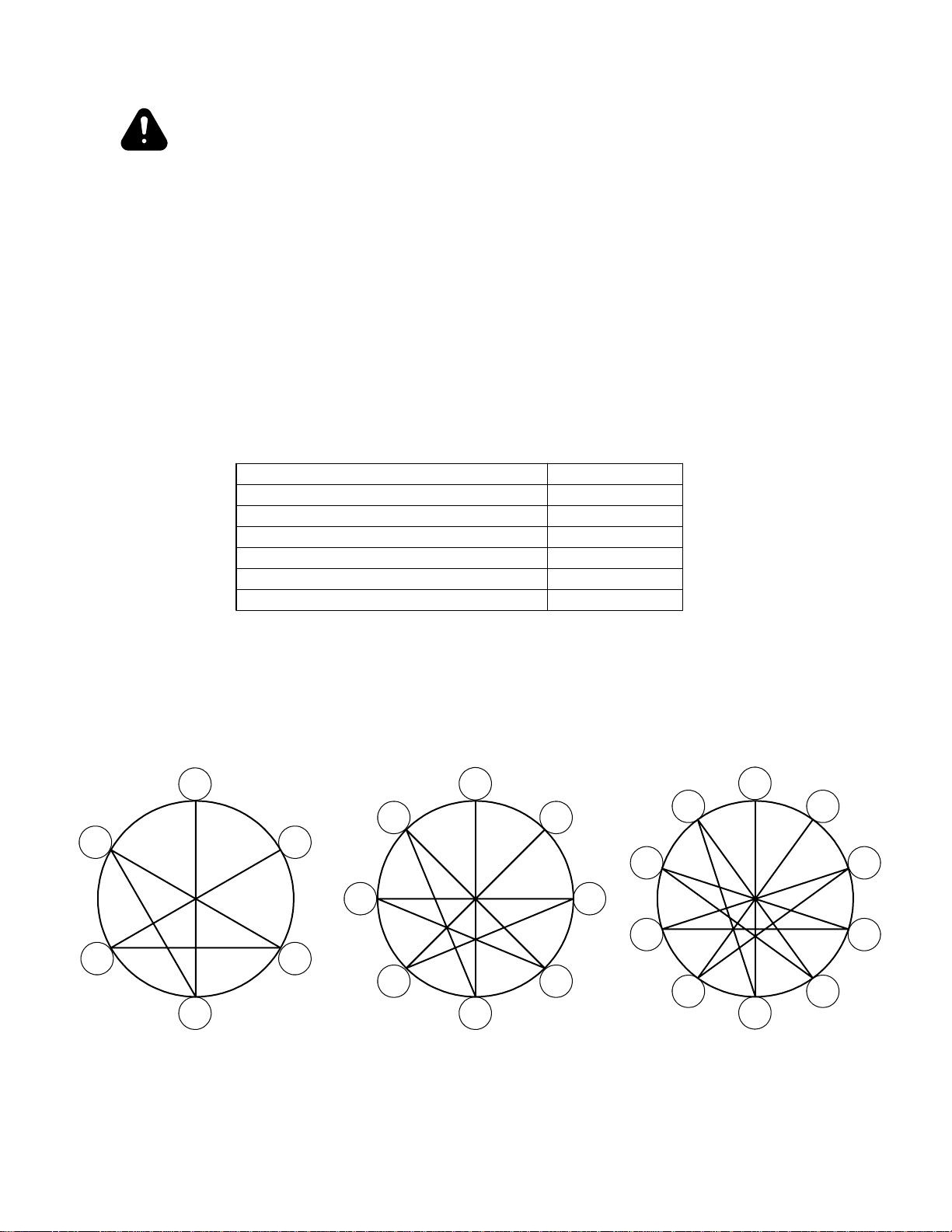
WARNING Both sides of the u-bolt
Do not tighten one side of the must be tightened equally.
u-bolt before the other side.
Table of Contents
General Information
Salford Recommended Torque Values.........................................................................................................3
Torque Values for Tires................................................................................................................................4
Pressure Values for Tires..............................................................................................................................5
General Safety Precautions..........................................................................................................................6
Frame & Tongue
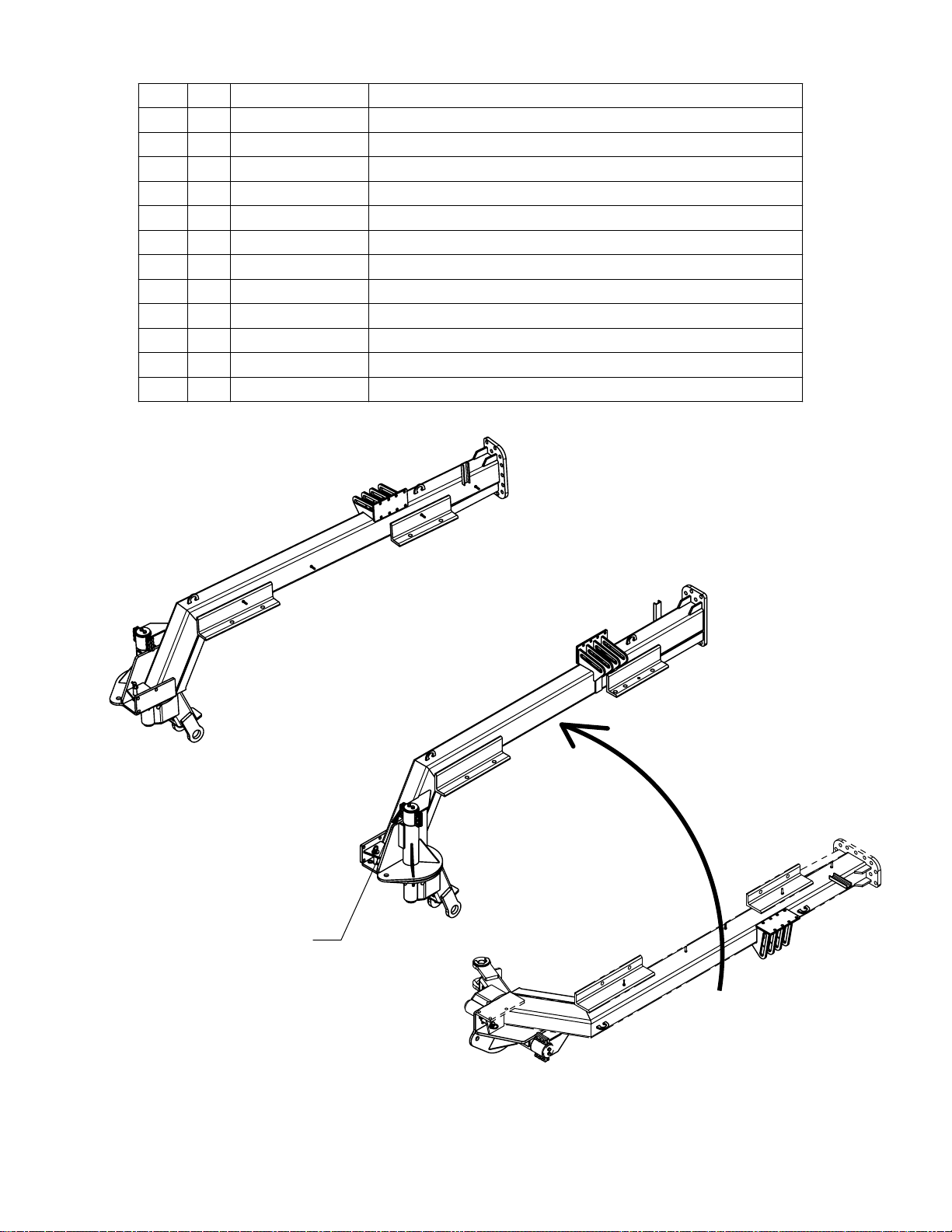
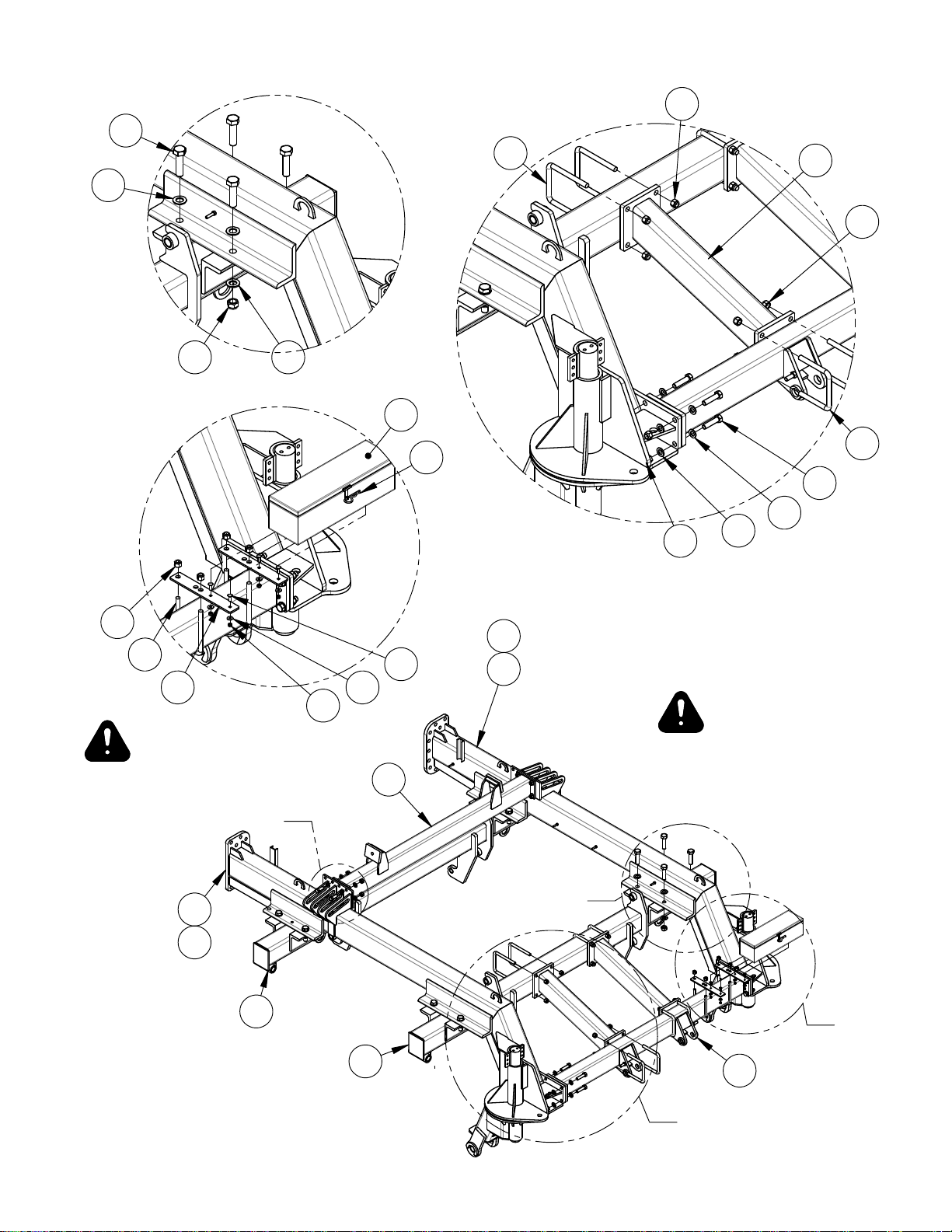
Main Caster Installation...............................................................................................................................8
Main Frame Assembly...............................................................................................................................10
Wing Frame Assembly...............................................................................................................................12
Wing Axle Beam Assembly.......................................................................................................................14
Wing Fold Parts .........................................................................................................................................16
Tongue Installation.....................................................................................................................................18
Operator Station.........................................................................................................................................20
Front Tandem Axle Assembly....................................................................................................................21
8000lb Hub and Spindle Assembly............................................................................................................22
5000lb Hub and Spindle Assembly............................................................................................................24
Toolbar Assembly
Main Frame Toolbar Assembly..................................................................................................................26
Wing Toolbar Assembly.............................................................................................................................28
Depth Control and Limit Switch Installation.............................................................................................30
Limit Switch Rephasing Instructions.........................................................................................................31
Coulters and Openers
522 - 30ft 7.5” Spacing with Coulters .......................................................................................................32
Coulter Assembly.......................................................................................................................................34
Coil-Tech Fertilizing Attachment ..............................................................................................................36
Coil-Tech Hub............................................................................................................................................38
Coil-Tech Hub............................................................................................................................................39
Opener Front Section Parts........................................................................................................................40
Opener Rear Section Parts.........................................................................................................................42
Opener Blade Parts ....................................................................................................................................44
Opener Lock-out........................................................................................................................................45
Air Distribution
520 Air Distribution Parts..........................................................................................................................46
522 - 30ft Air Distribution for 7.5” Spacing..............................................................................................48
522 - 30ft Air Distribution for 6 Tower 7.5” Spacing................................................................................50
Hydraulics
Double Toolbar Lift Hydraulics.................................................................................................................52
Wing Fold Hydraulics................................................................................................................................54
Safety Decals
Decal Locations .........................................................................................................................................56
Decal List...................................................................................................................................................58
Decal Legend.............................................................................................................................................59