Salford 9807 User manual

2012 9807 DRH
ASSEMBLY AND PARTS MANUAL
«» 396336
.,
-, .
, .
7. ( 4 «» 519 –
) ./ 8 (473)
233-28-17
E-mail: [email protected]
. 903-030-15-51
E-mail: [email protected]
: http://texagropark.ru/

Table of Contents
General Information
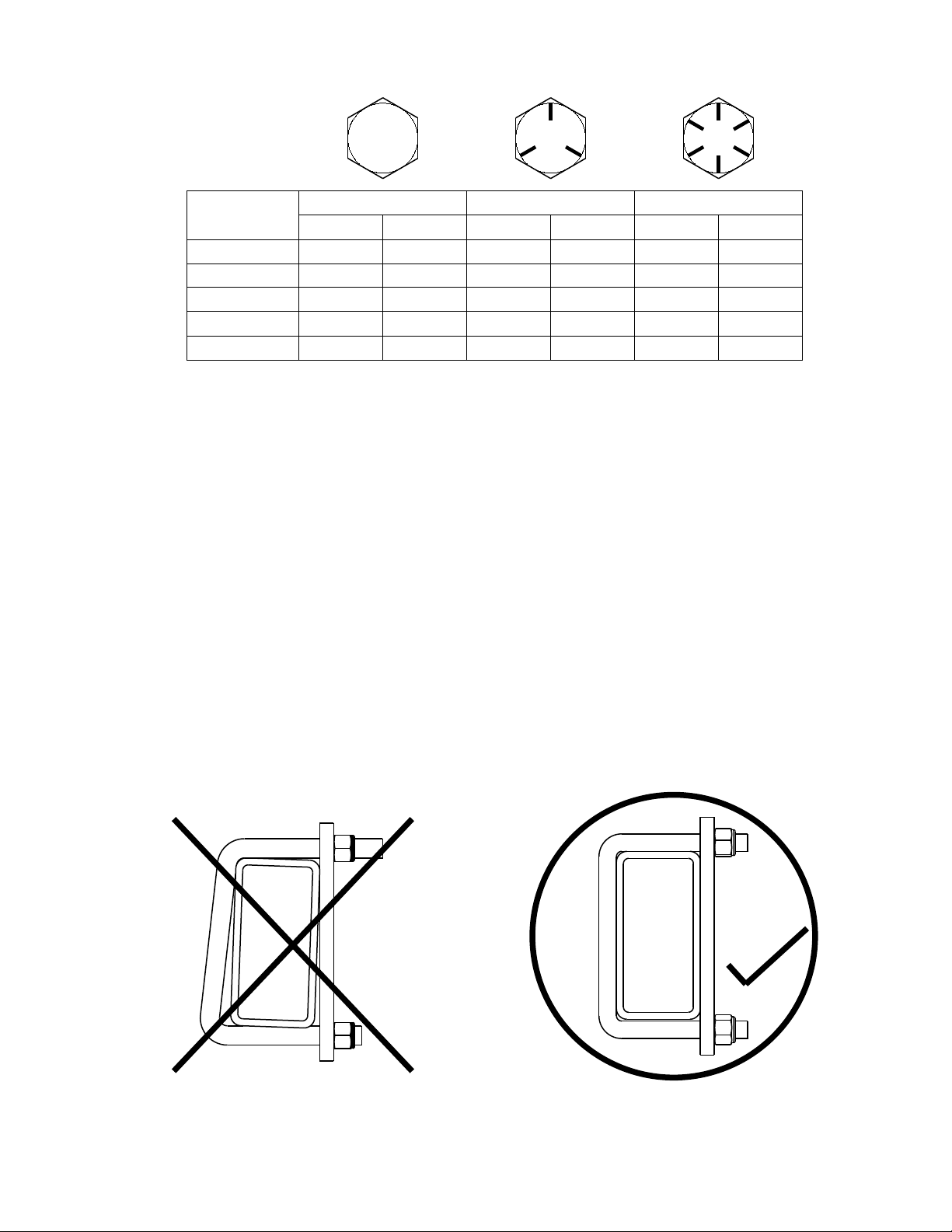
Salford Recommended Torque Values .........................................................................................................3
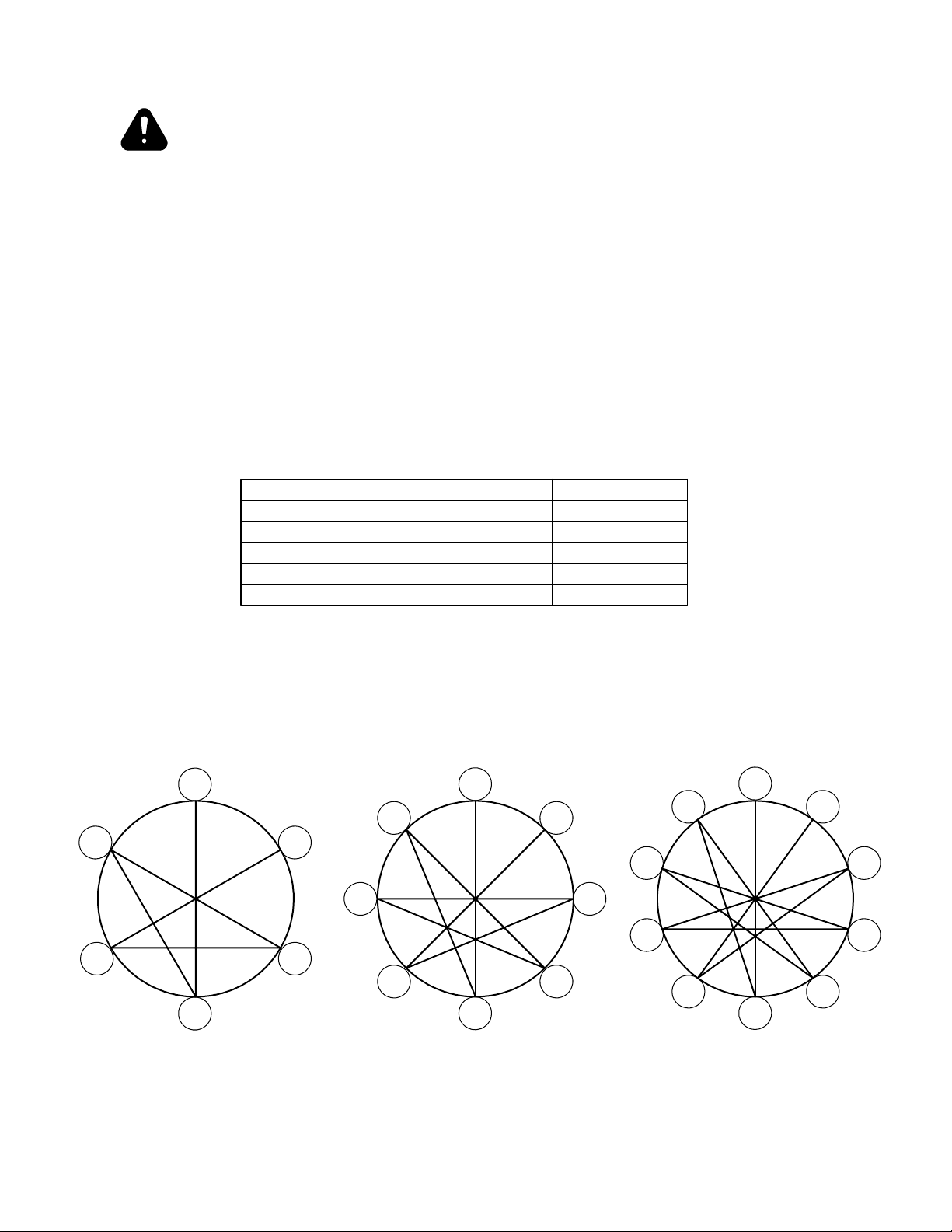
Wheel Torque Specications . ......................................................................................................................4
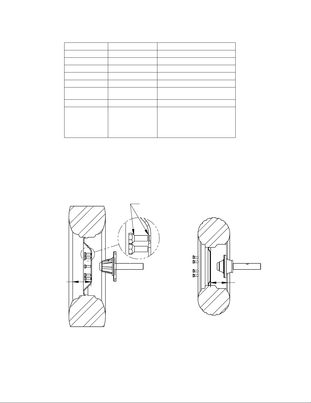
Tire Pressure Ratings ...................................................................................................................................5
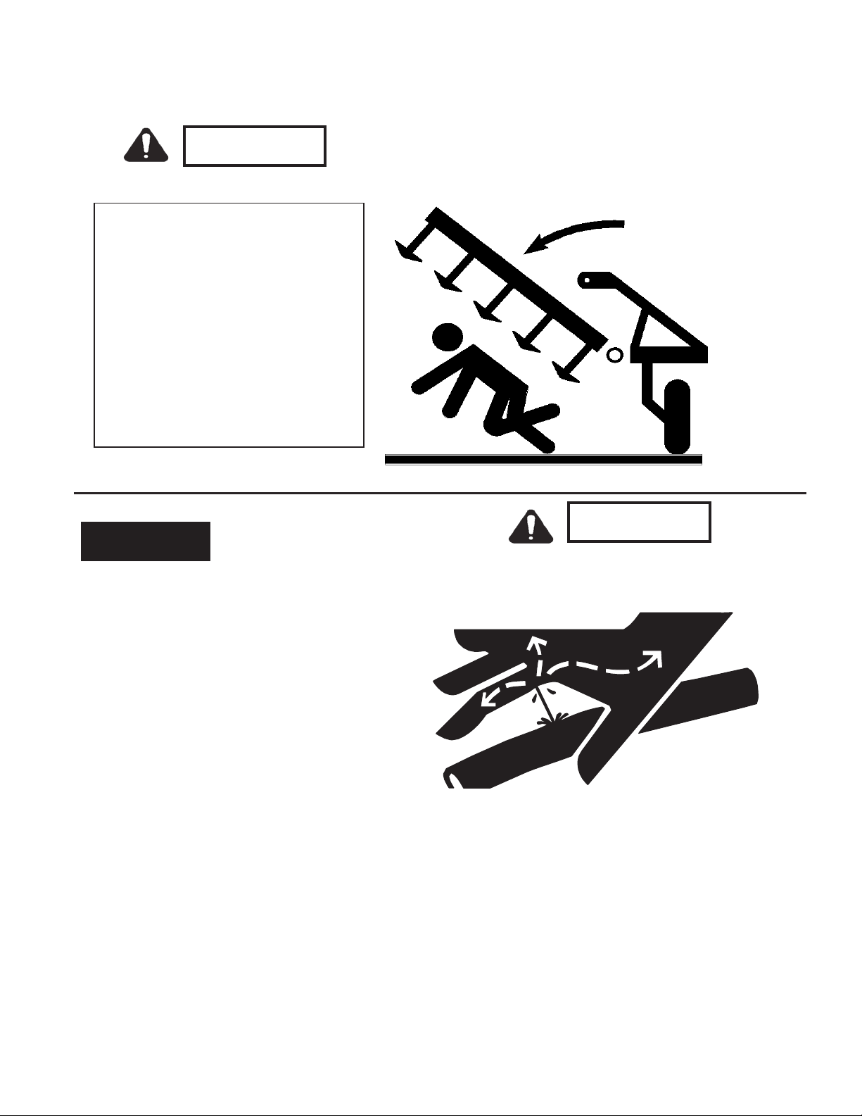
General Safety Precautions ..........................................................................................................................6
Frame and Tongue
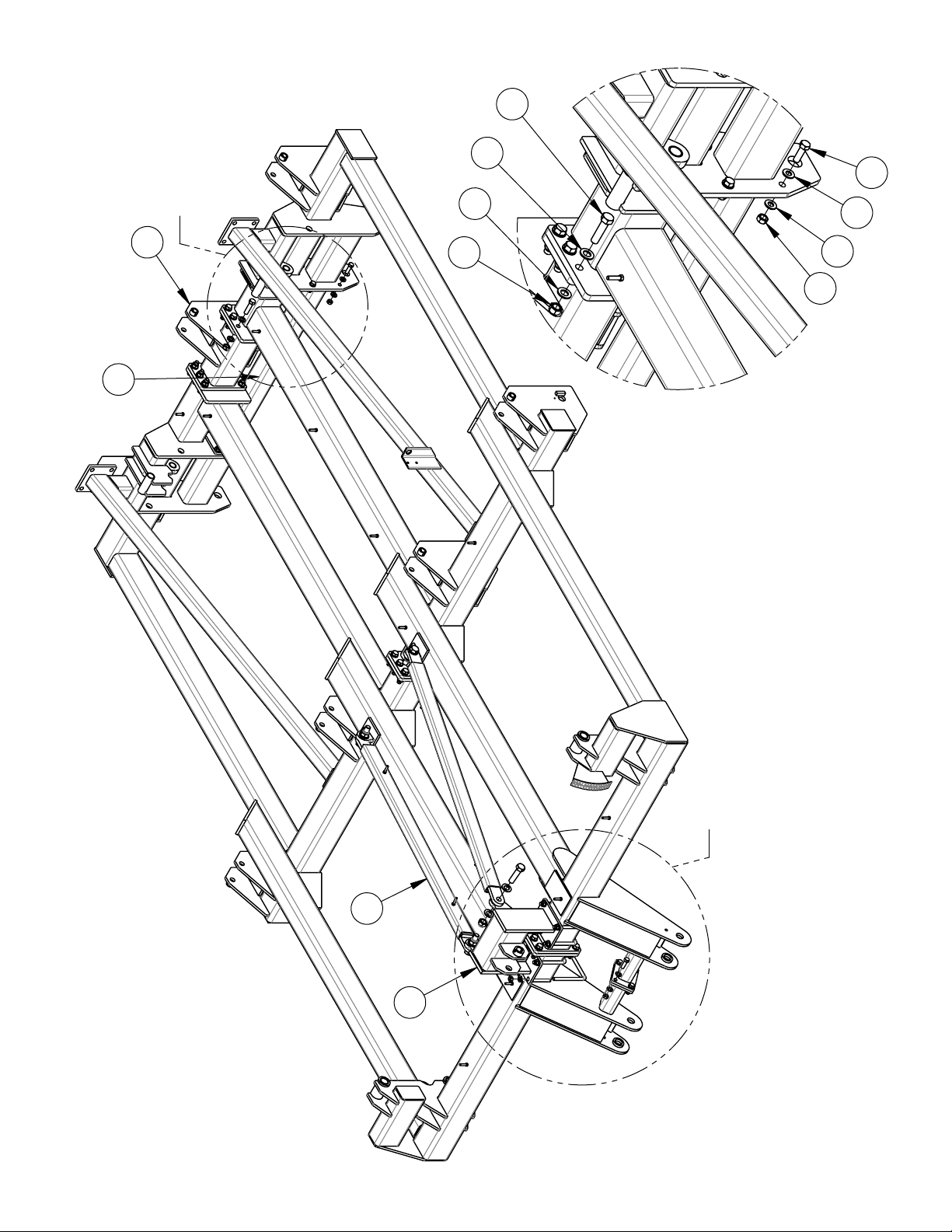
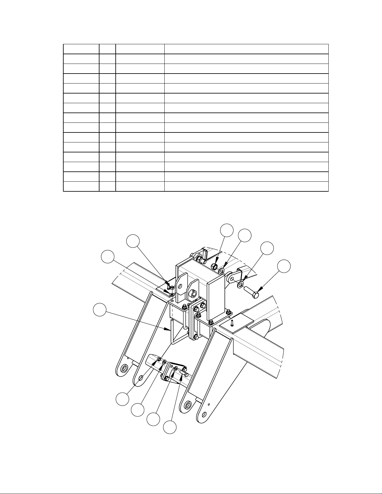
Frame Assembly. ..........................................................................................................................................8
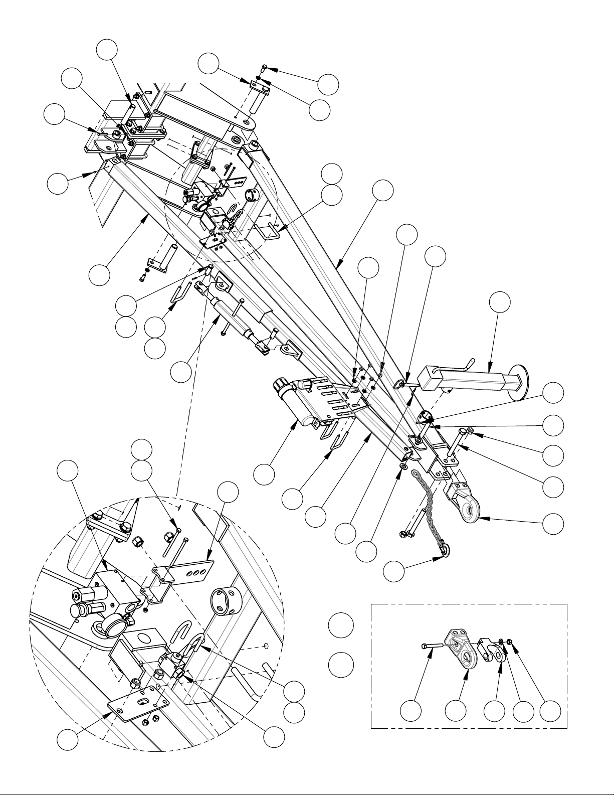
Tongue Installation.....................................................................................................................................10
Telescope Mount Hose Holder...................................................................................................................13
Axles and Depth Control
Axle Installation.........................................................................................................................................14
8000lb Hub and Spindle Assembly. ...........................................................................................................16
Depth Control Installation..........................................................................................................................18
Shank Assembly
Shank Assembly. ........................................................................................................................................20
Parabolic Shank Assembly. ........................................................................................................................22
Chisel Ripper Shank Assembly..................................................................................................................23
Auto Reset Spring Trip . .............................................................................................................................24
Shank Lockout . ..........................................................................................................................................27
Disc Gangs
Disc Gang Installation................................................................................................................................28
Coulter Mount Assembly & Rebuild Instructions .....................................................................................31
Disc Gang Layout . .....................................................................................................................................36
Harrows
Harrow Layout with 1/2” Tines .................................................................................................................37
Harrow Installation ....................................................................................................................................38
62” Long Harrow Arm Assembly . .............................................................................................................40
1/2” Tine Harrow Assemblies . ...................................................................................................................42
14” Roller Harrow Assemblies ..................................................................................................................44
Hydraulics & Lights
Axle Lift Hydraulics .................................................................................................................................46
Disc Gang Hydraulics . ..............................................................................................................................48
Lights & SMV Install.................................................................................................................................50
Decal Layout..............................................................................................................................................52
Salford Farm Machinery Ltd. 07-2012
2012 9807 Assembly and Parts Manual
: http://texagropark.ru/

6$/)25' 5(&200(1'(' 72548( 9$/8(6
BOLT SIZE GRADE 2 GRADE 5 GRADE 8
ft-lbs Nm ft-lbs Nm ft-lbs Nm
1/2"NC 50 68 75 102 105 142
5/8"NC 90 122 150 203 210 285
3/4"NC 160 217 270 366 375 508
7/8"NC 145 197 395 536 610 827
1"NC 210 285 590 800 910 1234
127(6: These recommended torque values are applicable when applied to the nut
only. These recommended torque values are approximate only. The torque-tension
relationship is affected by lubrication, surface finish, thread fit, plating, lock-washers, etc.
'2 127 use these values if a different torque value or tightening procedure is given for
a specific application. Torque values listed are for general use only. Check tightness of
fasteners periodically.
Shear bolts are designed to fail under predetermined loads. Always replace shear bolts
with identical grade.
Fasteners should be replaced with the same or higher grade. If higher-grade fasteners
are used, these should only be tightened to the strength of the original.
Make sure fasteners threads are clean and that you properly start thread engagement.
This will prevent them from failing when tightening.
WARNING Both sides of the u-bolt
Do not tighten one side of the must be tightened equally.
u-bolt before the other side.
07-2012 Page 3
Salford Farm Machinery Ltd.
2012 9807 Assembly and Parts Manual
Salford Recommended Torque Values
Return to Contents

WARNING
Maintain proper torque to provide safe and secure
attachment of the wheel hub/drum. Improperly tightened
wheel nuts can cause the wheel to separate from the wheel mounting surface
during operation. This could result in property damage, serious personal injury,
or possibly loss of life.
NOTE
- If wheel does not have chamfers to match profile of the nuts, use flat side of
nuts against rim face.
Install all lug nuts/bolts by hand to prevent cross threading and tighten lug nuts/bolts
following the steps and tightening sequence diagram below.
STEP 1) Torque to 20-25 ft•lbs following the appropriate pattern below.
STEP 2) Torque to 55-60 ft•lbs following the appropriate pattern below.
STEP 3) Torque to final ft•lbs rating (see bolt size below) following the
appropriate pattern below.
NOTE
- Recheck the torque settings of lug nuts/bolts after 10km (6 miles) and again
after 50km (30 miles). Periodically and at the beginning of each season check the
condition and the torque of the lug nuts/bolts.
5
3 6
4
1
22
1
4
6
3
5
7
8
5
67
1
2
3 10
8
49
6 LUG BOLT PATTERN 8 LUG BOLT PATTERN
10 LUG BOLT PATTERN
Lug Nut/Bolt Tightening Sequence
Bolt Size (Hub Size)
Final Torque
1/2" dia. bolt (up to 3000 lb hubs)
85 ft•lbs
9/16" dia. bolt (4000 - 5000 lb hubs)
120 ft•lbs
5/8" dia. bolt (5500 - 12000 lb hubs)
170 ft•lbs
3/4" dia. bolt (16000 - 20000 lb hubs) 300 ft•lbs
7/8" dia. bolt (25000 lb hubs)
450-500 ft•lbs
Salford Farm Machinery Ltd.
Page 4
2012 9807 Assembly and Parts Manual
07-2012
Wheel Torque Specications
Return to Contents

N
N
Deep dish
11L
245
425
Tires to install
deep dish in:
N
N
Deep Dish
12.5L
305
15 x 19.5
Tires to install
deep dish out:
If bolts/nuts are coned, ensure
proper seating in chamfer on rim.
Ensure proper inflation of each tire for safe operation and extended tire life.
NOTE
- Periodically and at the beginning of each season check the condition and the
pressure of each tire.
Tire Installation Direction
Do not rely on valve stem for orientation of
tires. It may face in or out on different rims.
Measure both sides of tire in to rim face. Install the
deep side in or out according to the instructions below.
Pressure [psi]
Pressure [bar]
Tire Size
25 [psi]
1.72 [bar]
23.1 x 26 (16 ply)
30 [psi]
2.07 [bar]
15 x 19.5 Lug Tire (6 ply)
35 [psi]
2.41 [bar]
Load Range C - 11L15
36 [psi]
2.48 [bar]
28L26 (16 ply)
52 [psi]
3.58 [bar]
30.5LR32 (181A8/B)
65 [psi]
4.48 [bar]
Load Range D - 11L15
- 12.5L15
70 [psi]
4.83 [bar]
15 x 19.5 Lug Tire (14 ply)
90 [psi]
6.20 [bar]
Load Range F - 11L15
- 12.5L15
Truck Tires - 245/70R19-5
- 305/70R22-5
- 425/60R22-5
07-2012 Page 5
Salford Farm Machinery Ltd.
2012 9807 Assembly and Parts Manual
Tire Pressure Ratings
Return to Contents

Signal Words
The words DANGER, WARNING or CAUTION are
used with the safety alert symbol. Learn to
recognize the safety alerts, and follow the
recommended precautions and safe practices.
Three words are used in conjunction with the safety-alert symbol:
DANGER
WARNING
Indicates an imminently hazardous situation that, if not
avoided, will cause DEATH OR VERY SERIOUS INJURY.
Indicates apotentially hazardous situation that, if not
avoided, could cause DEATH OR SERIOUS INJURY.
CAUTION Indicates apotentially hazardous situation that, if not
avoided, may result in MINOR or MODERATE INJURY.
Replace any DANGER, WARNING, CAUTION or
instructional decal that is not readable or is missing.
The location and part number of these
decals is identified later in this section of the
manual.
The words Important and Note are not related to
personal safety but are used to give
additional information and tips for
operating or servicing this equipment.
IMPORTANT: Identifies special instructions or
procedures which, if not strictly
observed could result in damage to, or
destruction of the machine, process or
its surroundings.
NOTE: Indicates points of particular interest for more efficient and convenient repair or operation.
A CAREFUL OPERATOR IS THE BEST INSURANCE AGAINST AN ACCIDENT !
Salford Farm Machinery Ltd.
Page 6
2012 9807 Assembly and Parts Manual
07-2012
General Safety Precautions
: http://texagropark.ru/
Return to Contents

•Wings may fall rapidly
causing injury.
•Always stay clear of wings
when being lowered, raised
or in a elevated state.
•Always use lockup device
provided when raised.
•Ensure cylinder is completely
filled with hydraulic fluid to
avoid unexpected
movement.
•DO NOT search for highpressure hydraulic
leaks without hand and face protection. A
tiny,almost invisible leak can penetrateskin,
thereby requiring immediatemedical
attention.
•Use cardboard or woodtodetect leaks –never
your hands.
•Double check that all is clear before
operating hydraulics.
•Never remove hydraulichoses or ends
with machine elevated.Relieve hydraulic
pressure before disconnecting hydraulic
hoses or ends.
•Maintainproper hydraulicfluid levels.
•Keep all connectorsclean for positive connections.
•Ensure all fittingsand hoses are in goodcondition.
•Do notstandunder wings.
General O
Hydraulics
DANGER
DANGER
07-2012 Page 7
Salford Farm Machinery Ltd.
2012 9807 Assembly and Parts Manual
General Safety Precautions
: http://texagropark.ru/
Return to Contents

A
B
2
3
4
1
DETAIL B
877
5
10
9
9
6
Salford Farm Machinery Ltd.
Page 8
2012 9807 Assembly and Parts Manual
07-2012
Frame Assembly
Return to Contents

A
B
2
3
4
1
DETAIL B
877
5
10
9
9
6
DETAIL A
14 12
12
13
10
9
11
6
9
9
10
9800 300hp FRAME ASSEMBLY
ITEM NO.
QTY
PART NO.
DESCRIPTION
1 1
W00294
2008 9800 300hp CENTRE SHANK MOUNT
2 1
W00297
2008 9800 AXLE TOWER BRACE
3 1
W00276
9800 300hp RIGID TELESCOPE MOUNT
4 2
C4505
65 1/2" PIN-PIN BRACE
5 24
B1230
3/4"NC x 3" LG. HEX BOLT
6 12
B1020
5/8 X 2" BOLT GR. 5 PLATED
7 48
BF12HS
3/4" HARD STRUCTURAL WASHER
8 24
BN12S
3/4" STOVER LOCK NUT
9 32
BF10HS
5/8" HARD STRUCTURAL FLAT WASHER
10 20
BN10S
5/8" NC STOVER LOCK NUT
11 4
BU1060
U-BOLT 5/8" x 6" x 7 1/2"
12 8
BF16HS
1" HARD STRUCTURAL WASHER
13 4
B1640
1"NC x 4" BOLT
14 4
BN16L
1-8 NC NYLOCK NUT
07-2012 Page 9
Salford Farm Machinery Ltd.
2012 9807 Assembly and Parts Manual
Frame Assembly
: http://texagropark.ru/
Return to Contents

21
19
20
23
9
5
3
2
31
29
15
26
25
24
14
7
17
16
27
18
6
32
4
22
11
8
10
12
13
CAT. 3 CLEVIS OPTION
1
30
28
Torque
21
&
23
to 220-250 ft/lbs
37 35
3435
39
38
41
40
33
42 36
13
Salford Farm Machinery Ltd.
Page 10
2012 9807 Assembly and Parts Manual
07-2012
Tongue Installation
Return to Contents

ITEM
NO.
QTY PART NUMBER
DESCRIPTION
1 1
W00271C
9800 300hp TONGUE WELDMENT
2 1 A60041
570-580-860-870-9700 INNER TELESCOPE
3 1 A60073
OUTER TELESCOPE 56"
4 1 A50010
TURNBUCKLE
5 2
GP1600258H04
PIN 1" DIA. x 2 5/8" LG. WITH HEAD
6 2
BSC0415
1/4" x 1 1/2" COTTER PIN
7 2
BSC0515
5/16" x 1 1/2" COTTER PIN
8 2
GPSPEC24080 1 1/2" x 8 1/4" LG. WING HINGE PIN
9 2
B1015 5/8 X 1 1/2" PLATED BOLT
10 1
B0625 3/8"NC x 2 1/2" LG. HEX BOLT
11 2
BL10 5/8" LOCKWASHER
12 1
GP2000614B07
PIN 1 1/4" DIA. x 6 1/4" LG. - 1 HOLE
13 5
BN06L
3/8"-16NC LOCK NUT
14 1
GP1600512A05
PIN 1" DIA. x 5 1/2" LG. - 2 HOLES
15 2
BF16
1" FLAT WASHER
16 2
B1680H
1" x 8" NC HEX BOLT GR. 8
17 2
BN16L
1-8 NC NYLOCK NUT
18 1
PPI-42XL
CAT 4 CAST IRON HITCH
19 1
PPI-30XL
CAT #3 CAST CLEVIS
20 1
PPI-208VR
CLEVIS FOR CAT 3 HITCH
21 1
B1255H
3/4" x 5 1/5" HEX BOLT GR. 8
22 1
BF12HS
3/4" HARD STRUCTURAL WASHER
23 1
BN12S
3/4" STOVER LOCK NUT
24 1
GJ8002
8000 LB TONGUE JACK
25 1
GP100414C03
5/8'' dia x 4 1/4'' pin RING & WASHER
26 1
GHP11 #11 HAIR PIN
27 1
GJ652027
20,000 LB SAFETY CHAIN
28 1 A60096A
TELESCOPE MOUNT HOSE HOLDER ASSEMBLY
29 2
BU0830
1/2" x 3" x 4 1/2" U-BOLT
30 4
BF08HS
1/2" HARD STRUCTURAL FLAT WASHER
31 4
BN08L
1/2" NYLOCK NUT NC
32 1
GF641
1/4"-28NF GREASE FITTING
33 1
L01411
BALL VALVE MOUNTING PLATE
34 1
BU103535
U-BOLT 5/8" x 3 9/16" x 5" LG.
35 4
BN10L
5/8" NYLOCK NUT NC
36 2
BN04L
1/4" LOCK NUT
37 1
BU1043
U-BOLT 5/8" x 4" x 4 1/2"
38 1
W00406 MOUNT FOR HV8263
39 1
HV8263
PRESSURE REDUCING VALVE W/ HI-FLOW RELIEF
40 1
HV1136
1/2" 2-WAY BALL VALVE
41 2
BUR061525
U-BOLT ROUND 3/8" x 1 1/2" x 2 1/2"
42 2
B0440
1/4" NC x 4" LG. HEX BOLT GR. 5
07-2012 Page 11
Salford Farm Machinery Ltd.
2012 9807 Assembly and Parts Manual
Tongue Installation
: http://texagropark.ru/
Return to Contents

2
3
5
8
7
9
Extra clamps for use on
machines requiring more
than two sets of hoses.
6
4
111210
1
9
9
8
ITEM
QTY
PART NO.
DESCRIPTION
1 1
A60096
TELESCOPE MOUNT HOSE HOLDER
2 1
G106
HD OPERATORS MANUAL HOLDER
3 1
GL11750
LIGHT PLUG HOLDER - PLASTIC
4 4
P0160B
HOSE CLAMP 4"
5 2
BC0630
3/8"NC x 3" LG. CARRIAGE BOLT
6 2
BN06L
3/8"-16NC LOCK NUT
7 2
BF04
1/4" FLATWASHER
8 5
BC0205
10-24 x 1/2" A307A LOW CARBON ZINC CARRIAGE BOLT
9 5
BN02L
#10-24 NYLOCK NUT
10 2
BU0830
1/2" x 3" x 4 1/4" U-BOLT
11 4
BN08L
1/2" NYLOCK NUT NC
12 4
BF08HS
1/2" HARD STRUCTURAL FLAT WASHER
THIS PAGE INTENTIONALLY LEFT BLANK
Salford Farm Machinery Ltd.
Page 12
2012 9807 Assembly and Parts Manual
07-2012
: http://texagropark.ru/
Return to Contents

2
3
5
8
7
9
Extra clamps for use on
machines requiring more
than two sets of hoses.
6
4
111210
1
9
9
8
ITEM
QTY
PART NO.
DESCRIPTION
1 1
A60096
TELESCOPE MOUNT HOSE HOLDER
2 1
G106
HD OPERATORS MANUAL HOLDER
3 1
GL11750
LIGHT PLUG HOLDER - PLASTIC
4 4
P0160B
HOSE CLAMP 4"
5 2
BC0630
3/8"NC x 3" LG. CARRIAGE BOLT
6 2
BN06L
3/8"-16NC LOCK NUT
7 2
BF04
1/4" FLATWASHER
8 5
BC0205
10-24 x 1/2" A307A LOW CARBON ZINC CARRIAGE BOLT
9 5
BN02L
#10-24 NYLOCK NUT
10 2
BU0830
1/2" x 3" x 4 1/4" U-BOLT
11 4
BN08L
1/2" NYLOCK NUT NC
12 4
BF08HS
1/2" HARD STRUCTURAL FLAT WASHER
07-2012 Page 13
Salford Farm Machinery Ltd.
2012 9807 Assembly and Parts Manual
Telescope Mount Hose Holder
Return to Contents

LH AXLE
ASSEMBLY
13
11
3
14
8
1
6
16
7
9
16
17
12
10
7
15
18
15
4
STANDARD
19
OPTIONAL
20
OPTIONAL
RH AXLE
ASSEMBLY
3
11
13
14
8
2
6
4
STANDARD
16
7
916
17
7
15
15
12
10
18
19 OPTIONAL
20 OPTIONAL
FOR 16.5L x 16.1 TIRES INSTALL 8000LB HUBS AS FAR
IN
AS POSSIBLE
FOR 425/65R22.5 TRUCK TIRES INSTALL 8000LB HUBS AS FAR
OUT
AS POSSIBLE
Refer to hydraulic layout
page for cylinder size
Put transport lock pin in holder for
field position. Put pin in transport
lock for storage or road transport.
5
Salford Farm Machinery Ltd.
Page 14
2012 9807 Assembly and Parts Manual
07-2012
Axle Installation
: http://texagropark.ru/
Return to Contents

CAUTION
*
Check: Wheel nuts/lugs for proper tightness.
(See torque & pressure values on tire page)
Connect hoses and charge lift axle cylinders with fluid
following the procedure in the axle lift hydraulics section of
this manual before connecting rod ends of the cylinders.
ITEM
QTY
PART NO.
DESCRIPTION
1 1
C00174L-KIT
9800 300 hp AXLE LH
2 1
C00174R-KIT
9800 300 hp AXLE RH
3 2
GW8000A
8000 lb GREASABLE HUB AND 14" SPINDLE ASSY
4 2
GW18228 425/65R x 22.5 x 8 BOLT WHEEL - RECAP
5 2
A60043
510/9700/9800 TRANSPORT LOCK
6 2
GP2401834A09
PIN 1 1/2" DIA. x 18 3/4" LG
7 4
GPHF2000312H05
1 1/4" x 3 1/2" SHOULDER PIN HARDENED W/ FLATS
8 2
GP1600258H04
PIN 1" DIA. x 2 5/8" LG. WITH HEAD
9 2
GP1600714C04
1" x 7 1/4" HITCH PIN
10 2
B1045
5/8 x 4-1/2" LG. HEX BOLT
11 2
BN10L
5/8" NYLOCK NUT NC
12 4
B0830
1/2"NC x 3" HEX BOLT
13 4
BN08L
1/2" NYLOCK NUT NC
14 2
BSC0415
1/4" x 1 1/2" COTTER PIN
15 4
BSC0520
5/16" x 2" COTTER PIN
16 4
GBB150125100
1 1/2" x 1 1/4" x 1" LG. HARD BUSHING
17 4
GF1610
1/8" NPT GREASE FITTING
18 4
GBB175150200
1 3/4" x 1 1/2" x 2" LG. HARD BUSHING
19 2
GW16168H 16.5L x 16.1 Fl E TIRE & RIM - 8 BOLT -1 1/2" OFFSET
20 2
GW15195
15 x 19.5 LUG TIRE WITH 8 BOLT WHEEL (14 PLY)
07-2012 Page 15
Salford Farm Machinery Ltd.
2012 9807 Assembly and Parts Manual
Axle Installation
: http://texagropark.ru/
Return to Contents

1
2
5
6
7
8
9
10
12
11
13
14
3
4
4
6
7
8
12
5
15
2
3
2
3
4
16
23
4
6
5
7
8
17
Entire assembly available as part number GW8000A (includes hub, spindle, bearings,
seal, dust cap, and hardware).
ITEM NO.
QTY
PART NUMBER
DESCRIPTION
1 1
GW8014
SPINDLE, 8 000 LBS.
2 1
GW8110VW
8000 LB V-SEAL GRASS WRAP GUARD
3 1
GW8110VS
8000 LB V-SEAL
4 1
GW8110VC 8000 LB V-SEAL COUNTERFACE
5 1
GB506849
8000 INNER CONE
6 1
GB506810
8000 INNER CUP
7 1
GB501310
8000 OUTER CUP
8 1
GB501349
8000 OUTER CONE
9 1
GW8108
1" SPINDLE WASHER
10 1
BN16S
1" SLOTTED HEX NUT
11 1
BSC0317
3/16" x 1 3/4" COTTER PIN
12 1
GW8112
8000 DUST CAP
13 8
BW1020
5/8" x 2" PRESS-IN WHEEL STUD
14 8
BW10
5/8" WHEEL LUG NUT
15 1
GW8000
8000 LB HUB WITH BEARINGS, V-SEAL, & DUSTCAP
16 1
GW8110V
8000 LB V-SEAL KIT
17 1
GW8111V
8000 LB BEARING WITH V-SEAL KIT
Salford Farm Machinery Ltd.
Page 16
2012 9807 Assembly and Parts Manual
07-2012
8000lb Hub and Spindle Assembly
: http://texagropark.ru/
Return to Contents

Entire assembly available as part number GW8000A (includes hub, spindle, bearings,
seal, dust cap, and hardware).
ITEM NO.
QTY
PART NUMBER
DESCRIPTION
1 1
GW8014
SPINDLE, 8 000 LBS.
2 1
GW8110VW
8000 LB V-SEAL GRASS WRAP GUARD
3 1
GW8110VS
8000 LB V-SEAL
4 1
GW8110VC
8000 LB V-SEAL COUNTERFACE
5 1
GB506849
8000 INNER CONE
6 1
GB506810
8000 INNER CUP
7 1
GB501310
8000 OUTER CUP
8 1
GB501349
8000 OUTER CONE
9 1
GW8108
1" SPINDLE WASHER
10 1
BN16S
1" SLOTTED HEX NUT
11 1
BSC0317
3/16" x 1 3/4" COTTER PIN
12 1
GW8112
8000 DUST CAP
13 8
BW1020
5/8" x 2" PRESS-IN WHEEL STUD
14 8
BW10
5/8" WHEEL LUG NUT
15 1
GW8000
8000 LB HUB WITH BEARINGS, V-SEAL, & DUSTCAP
16 1
GW8110V
8000 LB V-SEAL KIT
17 1
GW8111V
8000 LB BEARING WITH V-SEAL KIT
07-2012 Page 17
Salford Farm Machinery Ltd.
2012 9807 Assembly and Parts Manual
8000lb Hub and Spindle Assembly
: http://texagropark.ru/
Return to Contents

5"
10
9
5
1
6
4
9800 300hp DEPTH CONTROL INSTALLATION
7
2
8
3
11
Slide rod through hole before
attaching to axle bracket
Do not overtighten this bolt -
rod must be able to pivot freely
Salford Farm Machinery Ltd.
Page 18
2012 9807 Assembly and Parts Manual
07-2012
Depth Control Installation
Return to Contents

CAUTION
This boss must face
mounting bracket
Metal plug must be
installed in bottom port
(re-use from cylinder port)
Poppet pin to face
front of machine
ITEM NO.
QTY.
PART NO.
DESCRIPTION
1 1
W00176
CTS DEPTH CONTROL BRACKET (AXLE)
2 1
HPMSC10
STROKE CONTROL VALVE
3 1
C1008
DETENT ADJUSTABLE STOP
4 1
C1001
94" DEPTH CONTROL ROD
5 1
BU1046
U-BOLT 5/8" x 4" x 7 1/2" LG.
6 2
BN10L
5/8" NYLOCK NUT NC
7 2
B0525
5/16 x 2 1/2" BOLT
8 2
BN05L
5/16" LOCK NUT
9 1
B0820
1/2"NC x 2" LG. HEX BOLT
10 1
BN08L
1/2" NYLOCK NUT NC
11 1
BSC0415
1/4" x 1 1/2" COTTER PIN
9800 300hp DEPTH CONTROL INSTALLATION
After assembly is complete move machine all the way up and
down and watch for any interference throughout the cycle.
07-2012 Page 19
Salford Farm Machinery Ltd.
2012 9807 Assembly and Parts Manual
Depth Control Installation
: http://texagropark.ru/
Return to Contents

17
1
9 6
8
17
3
17
5
418
2
10
15
12 11 14
8
7
12
13
10
15
16
9
Use 90
fittings
where shank head
plate is near a beam
Shank head bolt
goes through plate
with anti-rotate tab
Salford Farm Machinery Ltd.
Page 20
2012 9807 Assembly and Parts Manual
07-2012
Shank Assembly
Return to Contents
Table of contents
Other Salford Farm Equipment manuals
Popular Farm Equipment manuals by other brands

Vicon
Vicon Andex 424 T Assembly instructions

DuraTech Industries
DuraTech Industries Haybuster Balebuster 2620 Operating Instructions and Parts Reference

Titan Attachments
Titan Attachments 48TRENCHER owner's manual

EASY COOPS
EASY COOPS 4x12 Chicken Coop Plan manual

Woods
Woods DS8.30E Operator's manual

KUHN
KUHN RW1600 Operation manual