S&C BankGuard PLUS Instruction Manual

April 27, 2020
© S&C Electric Company 2003-2020, all rights reserved Instruction Sheet 1011-540
BankGuard Plus®Control
Operation
Table of Contents
Section Page Section Page
Introduction
Qualified Persons ........................... 2
Read this Instruction Sheet ................... 2
Retain this Instruction Sheet. . . . . . . . . . . . . . . . . . . 2
Proper Application .......................... 2
Warranty .................................. 2
Safety Information
Understanding Safety-Alert Messages........... 3
Following Safety Instructions .................. 3
Replacement Instructions and Labels ........... 3
Safety Precautions ......................... 4
Control Hardware And Software
Applicable Software ......................... 5
Hardware and Faceplate ..................... 5
Control Software............................ 6
SCADA Communication Equipment ............. 6
Control Operation
Overvoltage Protection for Capacitor Banks ...... 7
Protection for Reactors ....................... 7
Automatic Control Features ................... 8
Ungrounded and Grounded Wye Shunt
Capacitor Banks.......................... 9
Ungrounded Wye Shunt Reactors ..............11
Signal Processing...........................12
Generating Reports .........................15
Saving And Loading Setup Configurations
Saving the Setup Configuration ................16
Loading a Saved Configuration ................16
Viewing IntelliLink®
Software Without Data ......................17
Using Snapshots (VM Files)
Saving Control Settings and Data to a Snapshot ...18
Viewing (Connect To) a Snapshot ..............18
Saving Changes Made to the Snapshot..........18
Generating a Report from a Snapshot ...........18
Creating a CFG File From a Snapshot ...........18
Updating Control Software ..................19

2 S&C Instruction Sheet 1011-540
Introduction
Qualified Persons WARNING
Only qualified persons who are knowledgeable in the installation, operation, and
maintenance of overhead and underground electric distribution equipment, along
with all associated hazards, may install, operate, and maintain the equipment covered
by this publication. A qualified person is someone who is trained and competent in:
• The skills and techniques necessary to distinguish exposed live parts from nonlive
parts of electrical equipment
• The skills and techniques necessary to determine the proper approach distances
corresponding to the voltages to which the qualified person will be exposed
• The proper use of special precautionary techniques, personal protective equipment,
insulated and shielding materials, and insulated tools for working on or near exposed
energized parts of electrical equipment
These instructions are intended ONLY for such qualified persons. They are not
intended to be a substitute for adequate training and experience in safety procedures
for this type of equipment.
Read this
Instruction Sheet NOTICE
Thoroughly and carefully read this instruction sheet and all materials included in
the product’s instruction handbook before installing or operating a BankGuard Plus
Control. Familiarize yourself with the Safety Information and Safety Precautions on
pages 3 and 4. The latest version of this publication is available online in PDF format
at sandc.com/en/support/product-literature/.
Retain this
Instruction Sheet
This instruction sheet is a permanent part of your BankGuard Plus Control. Designate
a location where you can easily retrieve and refer to this publication.
Proper Application WARNING
The equipment in this publication is only intended for specific application. The
application must be within the ratings furnished for the equipment. Ratings for the
are listed in the ratings table in Specification Bulletin 1011-31. The ratings are also
on the nameplate affixed to the product.
Warranty The warranty and/or obligations described in S&C’s Price Sheet 150, “Standard Conditions
of Sale–Immediate Purchasers in the United States,” (or Price Sheet 153, “Standard
Conditions of Sale–Immediate Purchasers Outside the United States,”) plus any special
warranty provisions, as set forth in the applicable product-line specication bulletin,
are exclusive. The remedies provided in the former for breach of these warranties shall
constitute the immediate purchaser’s or end user’s exclusive remedy and a fulllment of
the seller’s entire liability. In no event shall the seller’s liability to the immediate purchaser
or end user exceed the price of the specic product that gives rise to the immediate
purchaser’s or end user’s claim. All other warranties, whether express or implied or
arising by operation of law, course of dealing, usage of trade or otherwise, are excluded.
The only warranties are those stated in Price Sheet 150 (or Price Sheet 153), and THERE
ARE NO EXPRESS OR IMPLIED WARRANTIES OF MERCHANTABILITY OR FITNESS
FOR A PARTICULAR PURPOSE. ANY EXPRESS WARRANTY OR OTHER OBLIGATION
PROVIDED IN PRICE SHEET 150 (OR PRICE SHEET 153) IS GRANTED ONLY TO THE
IMMEDIATE PURCHASER AND END USER, AS DEFINED THEREIN. OTHER THAN AN
END USER, NO REMOTE PURCHASER MAY RELY ON ANY AFFIRMATION OF FACT OR
PROMISE THAT RELATES TO THE GOODS DESCRIBED HEREIN, ANY DESCRIPTION
THAT RELATES TO THE GOODS, OR ANY REMEDIAL PROMISE INCLUDED IN PRICE
SHEET 150 (or PRICE SHEET 153).

S&C Instruction Sheet 1011-540 3
Safety Information
Understanding
Safety-Alert
Messages
Several types of safety-alert messages may appear throughout this instruction sheet and
on labels and tags attached to the BankGuard Plus Control. Familiarize yourself with
these types of messages and the importance of these various signal words:
DANGER
“DANGER” identifies the most serious and immediate hazards that will likely result in
serious personal injury or death if instructions, including recommended precautions,
are not followed.
WARNING
“WARNING” identifies hazards or unsafe practices that can result in serious personal
injury or death if instructions, including recommended precautions, are not followed.
CAUTION
“CAUTION” identifies hazards or unsafe practices that can result in minor personal
injury if instructions, including recommended precautions, are not followed.
NOTICE
“NOTICE” identifies important procedures or requirements that can result in product
or property damage if instructions are not followed.
Following Safety
Instructions
If you do not understand any portion of this instruction sheet and need assistance, contact
your nearest S&C Sales Ofce or S&C Authorized Distributor. Their telephone numbers
are listed on S&C’s website sandc.com, or call the S&C Global Support and Monitoring
Center at 1-888-762-1100.
NOTICE
Read this instruction sheet thoroughly and carefully
before installing a BankGuard Plus Control.
Replacement
Instructions
and Labels
If additional copies of this instruction sheet are needed, contact your nearest S&C Sales
Ofce, S&C Authorized Distributor, S&C Headquarters, or S&C Electric Canada Ltd.
It is important that any missing, damaged, or faded labels on the equipment be replaced
immediately. Replacement labels are available by contacting your nearest S&C Sales
Office, S&C Authorized Distributor, S&C Headquarters, or S&C Electric Canada Ltd.

4 S&C Instruction Sheet 1011-540
Safety Precautions
DANGER
The BankGuard Plus Control line voltage input range is 93 to 276 Vac.
Failure to observe the precautions below will result in serious personal injury
or death.
Some of these precautions may differ from your company’s operating procedures
and rules. Where a discrepancy exists, follow your company’s operating procedures
and rules.
1. QUALIFIED PERSONS. Access to the BankGuard
Plus Control must be restricted only to Qualified
Persons. See the “Qualified Persons” section on
page 2.
2. SAFETY PROCEDURES. Always follow safe
operating procedures and rules. Always maintain
proper clearance from energized components.
3. PERSONAL PROTECTIVE EQUIPMENT. Always
use suitable protective equipment, such as rubber
gloves, rubber mats, hard hats, safety glasses, arc-
flash clothing, and fall protection, in accordance
with safe operating procedures and rules.
4. SAFETY LABELS. Do not remove or obscure any
of the “DANGER,” “WARNING,” “CAUTION,” or
“NOTICE” labels and tags. Remove tags ONLY if
instructed to do so.
5. MAINTAINING PROPER CLEARANCE. Always
maintain proper clearance from energized
components.

S&C Instruction Sheet 1011-540 5
Control Hardware and Software
Applicable Software
This instruction sheet was prepared for use with software
version UPPD106S or later releases.
The release date is available on the setup disk label.
For questions regarding the applicability of information in
this instruction sheet to future software releases, please
contact S&C.
This section describes various control components.
The following section,”Overview of Control Operations,”
explains how these components work together to monitor
and manage capacitor bank/reactor operation.
Hardware and Faceplate
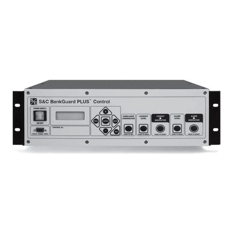
Figure 1 shows control hardware components that may
need to be accessible during regular operation and
troubleshooting.
The BankGuard Plus Control faceplate includes LEDs
and buttons for monitoring the capacitor bank/reactor and
the control. It also includes an LCD screen and buttons for
scrolling and selecting data.
Local communications port. The control has a port
on its faceplate for local communication. If the control
includes communication equipment, it will usually be con-
nected to the SCADA comm port on the back.
Terminal strips. Every BankGuard Plus Control
includes two numbered terminal strips for connecting to
the external control wiring. Their configuration is shown
in Instruction Sheet 1011-510, “S&C BankGuard Plus®
Control: Installation.”
Figure 1. The location of BankGuard Plus Control components.
Terminal strips
(on back)
Power supply
ON/OFF button
Faceplate Local
Communications
port
Faceplate LCD
and keypad

6 S&C Instruction Sheet 1011-540
Control Hardware and Software
Control Software
S&C controls are entirely software-driven. Each control
is shipped with control software and IntelliLink® Setup
software.
Control Software
Control software is preloaded into the control in the
factory. This software manages the minute-by-minute
functioning of the control. It continually monitors:
• Voltage on the feeder
• Incoming SCADA commands
• The state of the faceplate LEDs and buttons
• The internal control device clock/calendar
• The software setpoint values
• Various other setpoints and data values as needed
Based on this information, the control software decides
how to respond to a change in voltage, a command from the
faceplate or SCADA master station, and other conditions.
The control software, the setpoint values, and historical
data are all stored in nonvolatile switch control memory.
This memory survives power interruptions, including
complete loss of the battery system.
Battery Backed Non-volatile SRAM
The NVSRAM and real time clock/perpetual calendar
integrated circuit devices are battery-backed and have a
10-year battery life in the Non-Powered state. The real
time clock/perpetual calendar integrated circuit counts
seconds, minutes, hours, days, days of the week, date,
month, and year with leap-year compensation up to 2100.
IntelliLink Setup Software
IntelliLink Setup Software is supplied on the Setup disk
and runs on IBM/PC-compatible computers. This software
enables onsite communications with the control software.
Using the IntelliLink software, users can:
• Enter installation-dependent operating parameters
(setpoints), such as a network address, a voltage lockout
level, etc.
• Monitor real-time data, such as the present line-to-ground
voltage
• Transfer all conguration, operating, and historical data
from the control to a “report” le on your computer
• Download new control software into the control device
• Troubleshoot assorted types of control installation
problems
SCADA Communication Equipment
Most communication equipment can be mounted near the
control device.
DNP 3.0 is the standard protocol for the BankGuard
Plus Control; other protocol options are also available.
For more details, see the appropriate communication
points list or contact S&C.

S&C Instruction Sheet 1011-540 7
Control Operation
This section explains how the BankGuard Plus Controls
the capacitor bank or reactor.
Overvoltage Protection for Capacitor Banks
Medium to large wye-connected shunt capacitor banks
commonly use twofold protection against short circuits:
• Individual capacitor units are protected by fuse links
that clear internal faults, reducing the probability of
case ruptures.
• The system is protected against major faults by the
bank protective control, such as power fuses or an S&C
Circuit-Switcher.
If a fuse link operates to isolate a failed capacitor unit,
the voltage across remaining units in the same series group
will increase. This increased voltage can overstress and
shorten the life of the other capacitor units in the group.
As subsequent units fail, their isolation leads to further
voltage increase on the remaining units. The result is an
accelerating cascade of overvoltage that destroys good
capacitor units.
This phenomenon is addressed in IEEE Standard
18-1992, “IEEE Standard for Shunt Power Capacitors.” The
standard specifies a curve that indicates the permissible
capacitor unit operating time at varying per-unit multiples
of the capacitor nameplate voltage rating. See Figure 2.
This curve applies for up to 300 applications of power-
frequency overvoltages of the magnitude and duration
shown. (The standard further requires that capacitors
be capable of continuous operation to at least 110% of the
rated voltage, including harmonics. Most capacitor manu-
facturers publish similar data, which may permit higher
working voltages.) When the voltage applied to the surviv-
ing capacitor units exceeds the manufacturer’s maximum
recommended working voltage (or in the absence of a
recommendation, the IEEE standard), the entire bank
should be removed from service.
Thus, large-sized capacitor banks require a third form
of protection: a control sensitive enough to detect the
isolation of the first failed unit in a capacitor bank but
sophisticated enough to disregard system and inherent
bank imbalances, spurious transients, and harmonics.
Also, the ability to alarm upon isolation of that capacitor
unit lets the user replace it before additional failures occur.
Protection for Reactors
When a developing turn-to-turn fault occurs in any phase
winding, the ungrounded, wye-connected shunt reactor
is protected from further damage by automatic switching
initiated by the BankGuard Plus Control. The control also
will isolate and lock out the entire shunt reactor when a
predetermined neutral-to-ground voltage is exceeded.
Figure 2. Capacitor unit power-frequency overvoltage versus time (IEEE standard 18-1992).

8 S&C Instruction Sheet 1011-540
Control Operation
Automatic Control Features
The BankGuard Plus Control provides the automatic
features described in this section.
Bank/Reactor Lockout and Alarm
The Lockout logic includes a user-selectable time delay
(0.2 to 30 second). The time delay ensures the fuse for the
failing capacitor unit operates before the control locks
out the bank, so the failed capacitor unit can be quickly
located.
The BankGuard Plus Control includes a standard Alarm
function, which provides an alarm signal (after a time
delay) upon the loss of fewer capacitor units than that
corresponding to the Lockout Level setting. For many
capacitor banks it is practical to activate the alarm at the
loss of a single capacitor unit. This is a decided advantage
because replacement of the failed capacitor unit can be
accomplished at a convenient planned time instead of on
an urgent basis during a lockout resulting from subsequent
failure of capacitor units. If desired, the Alarm function
can alarm in respond to loss of control power to the
BankGuard Plus Control.
Alarms and lockouts are latched and maintained across
a software reset. They remain active until the ALARM
INDICATOR RESET button or a SCADA command resets
them.
Gross Overvoltage
If a ashover of series groups within the capacitor bank
or a failure of an entire reactor phase occurs, the Gross
Overvoltage logic lets the control react more quickly than
the normal lockout process. This logic is activated after a
eld-adjustable time delay of 0.2 to 5 seconds by such faults
producing a capacitor bank neutral-to-ground voltage in
excess of an adjustable level of 1000 to 5000 Volts.
The BankGuard Plus Control incorporates a digital
input actuated through a contact of the capacitor bank
switch-operator auxiliary switch. This digital input pre-
vents nuisance operation of the BankGuard Plus Control
Alarm or Lockout functions resulting from neutral-to-
ground voltages of several kilovolts being induced dur-
ing periods when the capacitor bank has been routinely
de-energized.
Unbalance Compensation
In larger capacitor banks, extraneous voltages can
introduce signicant errors in—or even overpower—the
voltage signal created by the loss of individual capacitor
units.
For example, a fixed error voltage may be present
because of inherent capacitor bank imbalances from
manufacturing-tolerance variations among individual
capacitor units, or because of system voltage imbalances
from non-transposition of overhead lines. A variable error
voltage may also be present because of a system load imbal-
ance from changing load conditions. (This error voltage is
usually only significant in very large, transmission-voltage
level capacitor banks.) Such an error voltage can cause
false operations that lock out the capacitor bank/reactor
or cause no operation when one is necessary.
The Unbalance Compensation feature (with the
addition of station-bus voltage monitoring devices on
ungrounded capacitor banks/reactors) lets the control
detect and compensate for the error voltage.

S&C Instruction Sheet 1011-540 9
Control Operation
Ungrounded and Grounded Wye Shunt
Capacitor Banks
The BankGuard Plus Control provides protection of
ungrounded (Figure 3) and grounded (Figure 4) wye-
connected shunt capacitor banks. As individual capacitor
units in a series group are isolated from the bank by their
respective fuses, the control automatically protects the
surviving capacitor units in the group from cascading
voltage overstress. The control locks out the entire bank
when the neutral-to-ground voltage exceeds the calculated
level. See Instruction Sheet 1011-530, “BankGuard Plus®
Control: Setup,” for more details
In general, the Unbalance Compensation feature
should be enabled if the magnitude of the error voltage
caused by system voltage imbalances and/or inherent
capacitor bank imbalances approaches 50% of the value of
the neutral-to-ground voltage calculated for one isolated
capacitor unit.
For ungrounded wye banks, the control uses an ana-
log input and digital voltmeter to detect the capacitor
bank neutral-to-ground voltage, as monitored by an S&C
15-Volt-Ampere Potential Device. A digital filter attenuates
harmonics and noise. When the Unbalance Compensa-
tion feature is disabled, the magnitude of the real-time
neutral-to-ground voltage is compared with the Gross
Over Voltage Level, Lockout Level, and Alarm Level
setpoint values, if enabled. Capacitor unit failures will
cause the real-time neutral-to-ground voltage magnitude
to change. If the real-time neutral-to-ground voltage mag-
nitude exceeds a setpoint value continuously for a time
greater than the applicable Time Delay setpoint value,
the appropriate control action is taken. The control will
lock the bank out if the Gross Over Voltage Level or the
Lockout Level setpoint value is exceeded. The control
will issue an alarm if the Alarm Level setpoint value is
exceeded.
Figure 3. A system diagram of a BankGuard Plus Control for ungrounded wye-connected capacitor banks.
Figure 4. A system diagram of a BankGuard Plus Control for grounded wye-connected capacitor banks.

10 S&C Instruction Sheet 1011-540
Control Operation
In addition to the neutral-to-ground potential device, one
30-Volt-Ampere S&C Potential Device is required to be
installed on any one of the line phases to obtain a reference
angle when the Unbalance Compensation feature is set in
the Cap Only setting. During the setup of the Unbalance
Compensation feature, a neutral-to-ground voltage
magnitude sample and a reference angle (Aref) sample
are used to obtain and store an approximate magnitude
correction value. See the “Signal Processing” section on
page 12 for an explanation of how the value is calculated.
Setup of the Unbalance Compensation feature should
be accomplished during a time when any voltage unbal-
ances caused by the loads are minimal. During each con-
trol cycle, the stored approximate magnitude correction
value is subtracted from the real-time neutral-to-ground
voltage magnitude to obtain a compensated neutral-to-
ground voltage magnitude. Capacitor unit failures will
cause the real-time neutral-to-ground voltage magnitude
to change and, therefore, change the compensated neutral-
to-ground voltage magnitude.
The control compares the compensated neutral-to-
ground voltage magnitude with the Gross Over Voltage
Level, Lockout Level, and Alarm Level setpoint values, if
enabled. If the compensated neutral-to-ground magnitude
exceeds a setpoint value continuously for a time greater
than the applicable Time Delay setpoint value, the appro-
priate control action is taken. The control will lock out the
bank if the Gross Over Voltage Level or the Lockout
Level setpoint value is exceeded or issue an alarm if the
Alarm Level setpoint value is exceeded. The Cap Only
value is generally selected when the voltage variations
between the line phases are expected to be negligible
in comparison to the neutral-to-ground voltage changes
resulting from the loss of capacitor units.
In addition to the neutral-to-ground potential device,
three S&C 30-Volt-Ampere Potential Devices are required
to be installed on each line phase when the Unbalance
Compensation feature is in the Cap/Line setting. The
control uses the three potential devices to obtain the
sum of the line voltages magnitude and a reference angle.
Because the sum is obtained from all the line voltages,
compensation for fixed system imbalances is provided.
During the setup of the Unbalance Compensation
feature, a neutral-to-ground voltage magnitude sample, a
sum of the line voltages sample, and the reference angle
are used to calculate and store a magnitude correction
value. See the “Signal Processing” section on page 12 for
an explanation of how the value is calculated. During each
control cycle, the stored magnitude correction factor is
subtracted from the real-time neutral-to-ground magni-
tude to obtain a compensated neutral-to-ground voltage
magnitude. Capacitor unit failures will cause the real-time
line-to-neutral voltage to change and, therefore, change
the compensated neutral-to-ground voltage magnitude.
The control compares the compensated neutral-to-
ground voltage magnitude to the Gross Over Voltage
Level, Lockout Level, and Alarm Level setpoint values,
if enabled. If the compensated neutral-to-ground voltage
magnitude exceeds a setpoint value continuously for a
time greater than the applicable Time Delay setpoint
value, the appropriate control action is taken. The control
will lock out the bank if the Gross Over Voltage Level
or the Lockout Level setpoint values are exceeded. The
control will issue an alarm if the Alarm Level setpoint
value is exceeded.
For grounded wye banks, the control uses Tap Volt-
age Calibration logic. This logic develops the sum of the
intermediate tap-point voltages on the three-phase legs, as
monitored by the S&C 30-Volt-Ampere Potential Devices.
A digital filter attenuates harmonics and noise.
When the Unbalance Compensation feature is dis-
abled, the magnitude of the sum of the intermediate tap-
point-to-neutral voltages is compared (in percent) with the
Gross Over Voltage Level, Lockout Level, and Alarm
Level setpoint values, if enabled. Capacitor unit failures
will cause the magnitude of the sum of the intermediate
tappoint-to-neutral voltages to change. If the real-time
magnitude of the sum exceeds a setpoint value continu-
ously for a time greater than the applicable Time Delay
setpoint value, the appropriate control action is taken. The
Control will lock the bank out if the Gross Over Voltage
Level or the Lockout Level setpoint value is exceeded.
The control will issue an alarm if the Alarm Level setpoint
value is exceeded.
In addition to the three 30-Volt-Ampere Potential
Devices, one 30-Volt-Ampere S&C Potential Device is
required to be installed on any one of the line phases to
obtain a reference angle when the Unbalance Compensa-
tion feature setpoint value is set in the Cap Only setting.
During setup of the Unbalance Compensation feature,
a sample of the magnitude of the sum of the intermediate
tap-point-to-neutral voltages and a reference angle sample
are used to obtain and store an approximate magnitude
correction value. See the “Signal Processing” section on
page 12 for an explanation of how the value is calculated.
Setup of the Unbalance Compensation feature should be
accomplished during a time when any voltage unbalances
caused by the loads are minimal. During each control
cycle, the stored approximate magnitude correction value
is subtracted from the magnitude of the real-time interme-
diate tap-point-to-neutral voltages sum.
Capacitor unit failures will cause the magnitude of the
real-time tap-point-to-neutral voltages sum to change, and
therefore, change the magnitude of the compensated tap-
point-to-neutral voltages sum. The control compares the
compensated intermediate tap-point-to-neutral voltages
sum magnitude with the Gross Over Voltage Level, Lock-
out Level, and Alarm Level setpoint values, if enabled.
If the compensated intermediate tap-point-to-neutral
magnitude exceeds a setpoint value continuously for a
time greater than the applicable time delay setpoint value,
the appropriate control action is taken. The control will
lockout the bank if the Gross Over Voltage Level or
the Lockout Level setpoint value is exceeded or issue
an alarm if the Alarm Level setpoint value is exceeded.
S&C Instruction Sheet 1011-540 11
Control Operation
Ungrounded Wye Shunt Reactors
The BankGuard Plus Control provides protection of
ungrounded, wye-connected shunt reactors--either three-
phase reactors or three-phase banks of single-phase
reactors. See Figure 5. The control detects turn-to-turn
faults in the windings of these shunt reactors, the most
common mode of reactor failure.
When a developing turn-to-turn fault occurs in any
phase winding, the shunt reactor is protected from further
damage by automatic switching provided by the control.
The control locks out the entire shunt reactor when the
neutral-to-ground voltage exceeds the calculated level. See
Instruction Sheet 1011-530, “BankGuard Plus® Control:
Setup,” for more details. In general, enable the Unbalance
Compensation feature if the magnitude of the calculated
error voltage caused by inherent reactor unbalance result-
ing from manufacturing-tolerance variations among the
phase windings approaches 50% of the desired Lockout
Level setting.
For ungrounded, wye-connected shunt reactors, the
control uses an analog input and digital voltmeter to detect
the reactor neutral-to-ground voltage, as monitored by
an S&C 15-Volt-Ampere Potential Device. A digital filter
attenuates harmonics and noise.
When the Unbalance Compensation feature is dis-
abled, the magnitude of the real-time neutral-to-ground
voltage is compared with the “Gross Over Voltage Level”,
“Lockout Level”, and “Alarm Level” setpoint values, if
enabled. Reactor-turn failures will cause the real-time
neutral-to-ground voltage magnitude to change. If the
real-time neutral-to-ground voltage magnitude exceeds
a setpoint value continuously for a time greater than the
applicable time delay setpoint value, the appropriate con-
trol action is taken. The control will lock the reactor out if
the Gross Over Voltage Level or Lockout Level setpoint
value is exceeded. The control will issue an alarm if the
Alarm Level setpoint value is exceeded.
In addition to the neutral-to-ground potential device,
one 30-Volt-Ampere S&C Potential Device is required to be
installed on any one of the line phases to obtain a reference
angle when the Unbalance Compensation feature is set
in the Reactor setting only. During the setup of the Unbal-
ance Compensation feature, a neutral-to-ground voltage
magnitude sample and a reference angle (Aref) sample
are used to obtain and store an approximate magnitude
correction value. See the “Signal Processing” section on
page 12 for an explanation of how the value is calculated.
The Unbalance Compensation feature set-up should
be accomplished during a time when any voltage unbal-
ances caused by the loads are minimal. During each control
cycle, the stored, approximate Magnitude Correction
value is subtracted from the real-time neutral-to-ground
voltage magnitude to obtain a compensated neutral-to-
ground voltage magnitude. Reactor-turn failures will
cause the real-time neutral-to-ground voltage magnitude
to change and, therefore, change the compensated neutral-
to-ground voltage magnitude. The control compares the
compensated neutral-to-ground voltage magnitude with
the Gross Over Voltage Level, Lockout Level, and
Alarm Level setpoint values, if enabled.
If the compensated neutral-to-ground magnitude
exceeds a setpoint value continuously for a time greater
than the applicable Time Delay setpoint value, the appro-
priate control action is taken. The control will lockout the
bank if the Gross Over Voltage Level or Lockout Level
setpoint value is exceeded, or issue an alarm if the Alarm
Level setpoint value is exceeded. The Reactor Only value
is generally selected when the voltage variations between
the line phases are expected to be negligible in comparison
to the neutral-to-ground voltage changes resulting from
the loss of reactor turns.
In addition to the neutral-to-ground potential device,
three S&C 30-Volt-Ampere Potential Devices are required
to be installed on each line phase when the Unbalance
Figure 5. A system diagram of a BankGuard Plus Control for ungrounded wye-connected shunt reactors.
Optional Sensing for
Unbalance Compensation function

12 S&C Instruction Sheet 1011-540
Control Operation
Compensation feature is set in the Reactor/Line setting.
The control uses the three potential devices to obtain the
sum of the line voltages magnitude and a reference angle.
Because the sum is obtained from all the line voltages,
compensation for fixed-system imbalances is provided.
During the set-up of the Unbalance Compensation fea-
ture, a neutral-to-ground voltage magnitude sample, and a
sum of the line voltages sample and the reference angle are
used to calculate and store a magnitude correction value.
See the “Signal Processing” section for an explanation of
how the value is calculated.
During each control cycle, the stored magnitude cor-
rection factor is subtracted from the real-time neutral-
to-ground magnitude to obtain a compensated neutral
to ground voltage magnitude. Reactor-turn failures will
cause the real-time line-to-neutral voltage to change and,
therefore, change the compensated neutral-to-ground volt-
age magnitude. The control compares the compensated
neutral-to-ground voltage magnitude to the Gross Over
Voltage Level, Lockout Level, and Alarm Level setpoint
values, if enabled. If the compensated neutral- to-ground
voltage magnitude exceeds a setpoint value continuously
for a time greater than the applicable time delay setpoint
value, the appropriate control action is taken. The control
will lock out the bank if the Gross Over Voltage Level
or the Lockout Level setpoint values are exceeded. The
control will issue an alarm if the Alarm Level setpoint
value is exceeded.
Signal Processing
The BankGuard Plus Control hardware samples the
sensor(s) analog output waveform and then converts
the samples to digital values. See Figure 6. The control’s
software processes the digital values using a Discrete
Fourier Transform algorithm and compares the results
to the applicable setpoint value. The comparisons are
made at 200 millisecond intervals. Upon completion of the
comparisons, control action is then taken, if appropriate.
When an ungrounded wye capacitor bank installation
has the Unbalance Compensation feature disabled, the
Discrete Fourier Transform algorithm yields the magnitude
of the neutral-to-ground voltage. This magnitude is then
compared to the setpoint value(s) to determine whether
any control action is to be executed.
When an ungrounded wye capacitor bank has the
Unbalance Compensation feature set is in the Cap Only
setting, the Discrete Fourier Transform algorithm yields
the magnitude of the neutral-to-ground voltage (|VN-G|)
and the value of the phase angle (Aref) between the neutral-
Figure 6. A BankGuard Plus Control diagram.
Figure 7. An approximate corrected magnitude.

S&C Instruction Sheet 1011-540 13
Control Operation
to-ground voltage and the reference line voltage. Using
the Law of Cosines, an approximate correct magnitude is
obtained using the reference angle. See Figure 7 on page 12.
An approximate corrected magnitude is calculated
and stored in the control’s memory during the feature’s
set-up procedure. When the control is operating, the
stored, approximate corrected magnitude is subtracted
from the real-time neutral-to-ground voltage magnitude
during each 200 milliseconds to obtain a compensated
neutral-to-ground voltage magnitude. The compensated
neutral-to-ground voltage magnitude is then compared
to the setpoint value(s). If the compensated neutral-to-
ground voltage magnitude exceeds a setpoint value, then
the appropriate control action will be taken.
For an ungrounded wye capacitor bank with the
Unbalance Compensation feature in the Cap/Line
setting, the Discrete Fourier Transform algorithm yields
the magnitude of the neutral-to-ground voltage, the mag-
nitude of the sum of the line voltages(|VL-G sum|) and a
reference angle (Aref). Because the sum is obtained from
the three line voltages, compensation for fixed system
voltage imbalances is provided in addition to capacitor
unit manufacturing tolerance. Using the Law of Cosines,
a corrected magnitude is obtained. See Figure 8. A cor-
rected magnitude is calculated and stored in the control’s
memory during the feature’s setup procedure. When the
control is operating, the stored corrected magnitude is
subtracted from the real-time neutral-to-ground voltage
each 200 milliseconds to obtain a compensated neutral-
to-ground voltage magnitude. The compensated neutral-
to-ground voltage magnitude is then compared to the
setpoint value(s).
Capacitor unit failures will cause a change to the real-
time neutral-to-ground voltage magnitude. Therefore, the
compensated neutral-to-ground voltage will also change.
If the compensated neutral-to-ground voltage magnitude
exceeds a setpoint value, then the appropriate control
action will be taken.
For a grounded wye capacitor bank installation with
the Unbalance Compensation feature disabled, the Dis-
crete Fourier Transform algorithm yields the magnitude
of the sum of the tap-point-to-ground voltages (in percent).
Capacitor unit failures will cause a change to the magni-
tude of the real-time sum of the tap-point-to-ground volt-
ages. If the magnitude of the sum of the tap-point-to-ground
voltages exceeds a setpoint value(s), then the appropriate
control action will be taken.
Figure 8. A corrected magnitude.
Figure 9. An approximate corrected magnitude.

14 S&C Instruction Sheet 1011-540
Control Operation
For a grounded wye capacitor bank with the Unbalance
Compensation feature in Enable mode, the Discrete
Fourier Transform algorithm yields the magnitude of the
sum of the intermediate tap-point voltages (|V tap sum|)
and the value of the phase angle (Aref) between the tap-
point voltages sum and the reference line voltage. Using
the Law of Cosines, an approximate corrected magnitude
is obtained using the reference angle. See Figure 9 on page
13. An approximate corrected magnitude is calculated
and stored in the control’s memory during the feature’s
setup procedure.
When the control is operating, the stored, approximate
corrected magnitude is subtracted from the real-time
tap-point-to-ground voltages magnitude (in percent)
during each 200 milliseconds to obtain a compensated
neutral-to-ground voltage magnitude. The compensated
neutral-to-ground voltage magnitude is then compared to
the setpoint value(s).
The calculation on the compensated Neutra l-To -
Ground Voltage value is the same as for an ungrounded,
wye-connected shunt capacitor bank. Capacitor unit fail-
ures will cause a change to the magnitude of the real-time
tap-point-to-ground voltages sum and the reference angle.
Therefore, the magnitude of the compensated neutral to
ground voltages sum magnitude will also change. If the
magnitude of the compensated tap-point-to-ground volt-
ages sum magnitude exceeds a setpoint value, the appro-
priate control action will then be taken.

S&C Instruction Sheet 1011-540 15
Generating Reports
The Report feature can be used to save the control
software settings and stored data to a computer as a CSV
(comma-separated value) le. The report can be kept as a
permanent record and the report data used in spreadsheets
or other types of programs.
Complete the following steps to generate report:
STEP 1. Connect a portable computer to the control and
start the IntelliLink software.
For details, see the “To Start the IntelliLink
Software” section in Instruction Sheet 1011-530,
“BankGuard Plus Control: Setup.” If the com-
puter is already connected to the control, this
step can be skipped.
STEP 2. From the Data menu, choose the Reports
option.
STEP 3. In the dialog box, select the type of report to
generate, and then click on the OK button.
There are four types of reports:
Full.Includes all the information contained
in the control
System Setup and Operation. Contains the
configuration data for the control
Troubleshooting Information. Contains
the information recorded in the troubleshoot-
ing logs
Historical Data. Contains the daily statis-
tics, the potential device profiles, the switching
data, and the log of power outages
STEP 4. In the Save Report dialog box, specify a name
and location for this report, and then click on
the OK button..
If a location is not specified, the file is saved
to the same directory as the program files for
this for this type of control. The extension “.CSV”
is added automatically.
When the report is complete, the message
“Task completed” appears on the status line of
the Writing Report dialog box.

16 S&C Instruction Sheet 1011-540
Saving and Loading Setup Congurations
If several controls use a similar setup conguration and
the same software version, the conguration can be saved
from one control and loaded into the others. Then, only
the setpoints that are different for each control must be
manually adjusted.
Saving a Setup Configuration
Complete the following steps to save a setup conguration:
STEP 1. Determine which control contains the
conguration to be saved.
STEP 2. Connect the computer to the selected control
and start the IntelliLink software.
For details, see the “To Start the IntelliLink
Software” section in Instruction Sheet 1011-530,
“BankGuard Plus Control: Setup.” If the com-
puter is already connected to the control, this
step can be skipped.
STEP 3. FromtheFilemenu,choose the SaveSetpoints
option.
STEP 4. In the Save Setpoints dialog box, specify a name
and location for this conguration le, and then
click on the Save button.
If a location is not specified, the file is saved
to the same directory as the program files for
this for this type of control. The extension
“.CFG” is added automatically.
Note: This process does not save the Location setting
(on the Setup screen) or the Communications RTU
Address setting (on Page 1 of the Communications
Setup screen).
Loading a Saved Configuration
Complete the following steps to load a saved conguration:
STEP 1. If necessary, connect the computer to the
control where the conguration will be loaded ,
and then start the IntelliLink software.
For details, see the “To Start the IntelliLink
Software” section in Instruction Sheet 1011-530,
“BankGuard Plus Control: Setup.” If the com-
puter is already connected to the control, this
step can be skipped.
STEP 2. From the File menu, choose the Open
Setpoints option.
STEP 3. In the dialog box, select the CFG le for the
conguration you want to load, and then click
on the Open button.
STEP 4. Make any setpoint changes that are required for
this control.
For details, see the “To Start the IntelliLink
Software” section in Instruction Sheet 1011-530,
“BankGuard Plus Control: Setup.”
NOTICE
Be sure to enter the correct values for Location
setting (on the Setup screen) and, if necessary, the
Communications RTU Address setting (on Page 1
of the Communications Setup screen).

S&C Instruction Sheet 1011-540 17
Viewing IntelliLink Software Without Data
To view the IntelliLink software screens and Help le
without connecting to a control or a snapshot:
STEP 1. Start the IntelliLink software on a computer.
STEP 2. During startup, click on the Cancel button to
close the Connect dialog box.
If the IntelliLink software is already run-
ning, choose the Disconnect option from the
Connection menu, and then choose the Close
Screenset option from the File menu to clear
the present screenset from memory.
STEP 3. From the File menu, choose the Open
Screenset option.
STEP 4. In the Open Screenset dialog box, nd and
select the WMN le whose name matches the
version name on the Setup software disk for this
control.

18 S&C Instruction Sheet 1011-540
Using Snapshots (VM Files)
Operational and data-logging information can be saved in
“snapshots” (VM, virtual memory les). These snapshots
let users view data, generate a report, and save or change
setpoint congurations even when not connected to a
control. To access the stored information, “connect” to
the snapshot instead of the physical control. Each control
Setup disk includes a sample snapshot.
Saving Control Settings and Data to a
Snapshot
Use the following procedure to save operational and data-
logging information:
STEP 1. Connect a computer to the control whose
information is to be saved, and then start the
IntelliLink software.
For details, see the “To Start the IntelliLink
Software” section in Instruction Sheet 1011-530,
“BankGuard Plus Control: Setup.” If the com-
puter is already connected to the control, this
step can be skipped.
STEP 2. From the File menu, choose the Save Snapshot
option.
STEP 3. Inthedialogbox, specify a lenameand location
for this snapshot, and then click on the Save
button.
If a location is not specified, the file is saved
to the same directory as the program files for
this for this type of control. The extension “.VM”
is added automatically.
Viewing (Connect To) a Snapshot
Use the following procedure to view or connect to a
snapshot:
STEP 1. Start the IntelliLink software on a computer.
During startup, click on the Cancel button to
close the Connect dialog box.
If the IntelliLink software is already run-
ning, choose the Disconnect option from the
Connection menu, and then choose the Close
Screenset option from the File menu to clear
the present screenset from memory.
STEP 2. FromtheFilemenu,choosetheOpenSnapshot
option.
The Open Controller Data File dialog box
opens.
STEP 3. Select the snapshot desired to use, and then
click on the Open button.
STEP 4. If the conguration settings in the snapshot are
to be changed, click on the Yes button at the
Connectto File dialog box. Toavoid accidentally
changing a setting, click on the No button.
The IntelliLink software opens and displays
the contents of the selected snapshot.
Saving Changes Made to the Snapshot
All changes made to conguration settings in the snapshot
are automatically saved to disk immediately. There is no
need to “save” the changes in a separate operation.
Generating a Report From a Snapshot
Follow the same procedure used when connecting to a
control. For details, see the “Generating Reports” section
on page 15.
Creating a CFG File From a Snapshot
Complete the following procedure to prepare a setpoint
conguration for a control in the eld while not having
access to a comparable device:
STEP 1. Connect to the snapshot.
For details, see the “Viewing (Connect To) a
Snapshot” section.
STEP 2. Change the conguration settings in the
snapshot as needed.
For details, see the “To Start the IntelliLink
Software” section in Instruction Sheet 1011-530,
“BankGuard Plus Control: Setup.”
STEP 3. FromtheFilemenu,choosetheSaveSetpoints
option.
STEP 4. In the Save Setpoints dialog box, specify a name
and location for this conguration le, and then
click on the Save button.
If a location is not specified, the file is saved
to the same directory as the program files for
this for this type of control. The extension
“.CFG” is added automatically.
NOTICE
This process does not save the Location setting
(on the Setup screen) or the Communications RTU
Address setting (on page 1 of the Communications
Setup screen).

S&C Instruction Sheet 1011-540 19
Updating Control Software
Occasionally, the software stored in the control (the
control software) may need to be updated. The Update
program, installed with the IntelliLink software, enables
the earlier control software to be replaced with the later
version.
NOTICE
The setpoint values and historical data stored in
the control may be lost during the update process.
Generate all required reports using the original
IntelliLink and control software before updating the
control software.
Complete the following steps to update the software:
STEP 1. Install the contents of the new Setup disk on the
computer.
For details, see the “To Start the IntelliLink
Software” section in Instruction Sheet 1011-530,
“BankGuard Plus Control: Setup.”
STEP 2. Connect the computer to the LOCAL COMM
PORT or optical port on the control.
STEP 3. Start the Update program.
(a) In Windows, choose Start menu > Programs
> EnergyLine > Update.
The Update window appears (Figure 10).
(b) Select the desired options, and then click on
the Start Update button.
Note: If the control is not connected to COM1 on the
computer, click on the Communication Setup tab,
select the correct comm port, click on the Connect but-
ton, return to the Update Control Device Software
tab, and click on the Start Update button.
The update process takes 5 to 10 minutes. The process
can be followed in the lower right corner of the window.
When the update is complete, the window automatically
closes.
NOTICE
If the Update process is cancelled once it has started,
the software in the control can be deactivated. If the
process must be cancelled, start the Update process
again.
Note: If the software on the disk is not the same type as
the software in the control, an error message appears.
Note which software version is in the control, and then
press <Enter> key to abort the Update process. When
the correct new software version is obtained, repeat the
steps above.
Figure 10. Control Device Software Update Window
Other manuals for BankGuard PLUS
4
Table of contents
Other S&C Controllers manuals

S&C
S&C BankGuard PLUS Guide

S&C
S&C PMH Installation instructions

S&C
S&C Micro-AT User manual

S&C
S&C Vista SD Owner's manual

S&C
S&C Vista Owner's manual

S&C
S&C PMH Operation and maintenance manual

S&C
S&C IntelliCap User manual

S&C
S&C 6800 Series User manual

S&C
S&C Micro-AT User manual

S&C
S&C Micro-AT Instruction Manual

S&C
S&C TripSaver II User manual

S&C
S&C IntelliCap Plus Operating instructions

S&C
S&C BankGuard PLUS Manual

S&C
S&C 6800 Series User manual

S&C
S&C 6800 Series Parts list manual

S&C
S&C 6802 User guide

S&C
S&C IntelliCap Instruction Manual

S&C
S&C Vista SD Owner's manual

S&C
S&C BankGuard PLUS User manual

S&C
S&C GridMaster User manual