S&C Micro-AT User manual

January 20, 2020
© S&C Electric Company 2012-2020, all rights reserved Instruction Sheet 515-600
MIcro-AT®Source-Transfer Control
In a Weatherproof Enclosure
Installation, Field Programming, and Operation
Table of Contents
Section Page Section Page
Introduction
Qualified Persons ........................... 2
Read this Instruction Sheet ................... 2
Retain this Instruction Sheet .................. 2
Proper Application .......................... 2
Warranty .................................. 2
Safety Information
Understanding Safety-Alert Messages........... 3
Following Safety Instructions .................. 3
Replacement Instructions and Labels ........... 3
Safety Precautions ......................... 4
Overview
General ................................... 5
Voltage Sensing ............................ 9
Unbalance Detection ........................ 9
Overcurrent Lockout .........................10
Remote Indication...........................10
Test Panel .................................10
Supervisory Control .........................10
Communications Card .......................10
Wi-Fi Adapter Kit ...........................10
Operating Description
Normal Condition ...........................11
Transfer on Loss-of-Source Voltage.............11
Transfer on Return-of-Source Voltage ...........11
Transfer on Unbalance Condition...............12
Overcurrent Lockout Condition.................12
Installation ................................ 14
Features
The Display................................16
Error Messages ............................18
Non-Numeric Items .........................19
Ready-Only Items ..........................19
Field Adjustment and Programming......... 20
Configure Menu ............................21
Voltage Menu ............................. 25
Current Menu ............................. 26
Time Menu ............................... 27
Test Menu ................................ 28
Operational Testing
Loss-of-Source Testing...................... 30
Overcurrent-Lockout Testing ..................31
Before Walking Away ....................... 32
Diagnostic Tools
Event Menu............................... 33
Examine Menu ............................ 34
Maintenance .............................. 35
Specifications ............................. 36
Appendix
Non-Field Adjustable Items in the
Configure Menu ......................... 38
Non-Field Adjustable Items in the
Voltage Menu .......................... 38
Event Identification Code Numbers in the
Event Menu ............................ 39
Discrete Inputs in the Examine Menu ...........41
Discrete Outputs in the Examine Menu ..........41
Spare Circuit Cards ........................ 42
Spare Front Panel Assemblies ................ 42
Static-Dissipative Work Surface .............. 42
Note: Micro-AT control instruction sheets are posted as PDF files at sandc.com/en/support/product-literature/.
Matlink™ software (all revisions) and the Human Machine Interface (HMI) software application installer (for Wi-Fi
adapter users) are available for download at sandc.com/en/support/sc-customer-portal/. If assistance is needed,
contact customerportal@sandc.com, or call (888) 762-1100.

2 S&C Instruction Sheet 515-600
Introduction
Qualified Persons WARNING
Only qualified persons who are knowledgeable in the installation, operation, and
maintenance of overhead and underground electric distribution equipment, along
with all associated hazards, may install, operate, and maintain the equipment covered
by this publication. A qualified person is someone who is trained and competent in:
• The skills and techniques necessary to distinguish exposed live parts from nonlive
parts of electrical equipment
• The skills and techniques necessary to determine the proper approach distances
corresponding to the voltages to which the qualified person will be exposed
• The proper use of special precautionary techniques, personal protective equipment,
insulated and shielding materials, and insulated tools for working on or near exposed
energized parts of electrical equipment
These instructions are intended ONLY for such qualified persons. They are not
intended to be a substitute for adequate training and experience in safety procedures
for this type of equipment.
Read this
Instruction Sheet NOTICE
Thoroughly and carefully read this instruction sheet and all materials included in
the product’s instruction handbook before installing or operating your Micro-AT
Source Transfer Control. Familiarize yourself with the Safety Information and Safety
Precautions on pages 3 through 4. The latest version of this publication is available
online in PDF format at sandc.com/en/support/product-literature/.
Retain this
Instruction Sheet
This instruction sheet is a permanent part of your Micro-AT Source-Transfer Control.
Designate a location where you can easily retrieve and refer to this publication.
Proper Application WARNING
The equipment in this publication is only intended for a specific application. The
application must be within the ratings furnished for the equipment. Ratings for the
Micro-AT Source-Transfer Control are listed in the ratings table in Specification
Bulletin 515-31.
Warranty The warranty and/or obligations described in S&C’s Price Sheet 150, “Standard Conditions
of Sale–Immediate Purchasers in the United States,” (or Price Sheet 153, “Standard
Conditions of Sale–Immediate Purchasers Outside the United States”), plus any special
warranty provisions, as set forth in the applicable product-line specication bulletin,
are exclusive. The remedies provided in the former for breach of these warranties shall
constitute the immediate purchaser’s or end user’s exclusive remedy and a fulllment of
the seller’s entire liability. In no event shall the seller’s liability to the immediate purchaser
or end user exceed the price of the specic product that gives rise to the immediate
purchaser’s or end user’s claim. All other warranties, whether express or implied or
arising by operation of law, course of dealing, usage of trade or otherwise, are excluded.
The only warranties are those stated in Price Sheet 150 (or Price Sheet 153), and THERE
ARE NO EXPRESS OR IMPLIED WARRANTIES OF MERCHANTABILITY OR FITNESS
FOR A PARTICULAR PURPOSE. ANY EXPRESS WARRANTY OR OTHER OBLIGATION
PROVIDED IN PRICE SHEET 150 (OR PRICE SHEET 153) IS GRANTED ONLY TO THE
IMMEDIATE PURCHASER AND END USER, AS DEFINED THEREIN. OTHER THAN AN
END USER, NO REMOTE PURCHASER MAY RELY ON ANY AFFIRMATION OF FACT OR
PROMISE THAT RELATES TO THE GOODS DESCRIBED HEREIN, ANY DESCRIPTION
THAT RELATES TO THE GOODS, OR ANY REMEDIAL PROMISE INCLUDED IN PRICE
SHEET 150 (or PRICE SHEET 153).

S&C Instruction Sheet 515-600 3
Understanding
Safety-Alert
Messages
Several types of safety-alert messages may appear throughout this instruction sheet
and on labels and tags attached to your Micro-AT Source-Transfer Control. Familiarize
yourself with these types of messages and the importance of these various signal words:
DANGER
“DANGER” identifies the most serious and immediate hazards that will likely result in
serious personal injury or death if instructions, including recommended precautions,
are not followed.
WARNING
“WARNING” identifies hazards or unsafe practices that can result in serious personal
injury or death if instructions, including recommended precautions, are not followed.
CAUTION
“CAUTION” identifies hazards or unsafe practices that can result in minor personal
injury if instructions, including recommended precautions, are not followed.
NOTICE
“NOTICE” identifies important procedures or requirements that can result in product
or property damage if instructions are not followed.
Following Safety
Instructions
If you do not understand any portion of this instruction sheet and need assistance, contact
your nearest S&C Sales Ofce or S&C Authorized Distributor. Their telephone numbers
are listed on S&C’s website sandc.com, or call the S&C Global Support and Monitoring
Center at 1-888-762-1100.
NOTICE
Read this instruction sheet thoroughly and carefully
before installing your Micro-AT Source-Transfer
Control.
Replacement
Instructions
and Labels
If additional copies of this instruction sheet are needed, contact your nearest S&C Sales
Ofce, S&C Authorized Distributor, S&C Headquarters, or S&C Electric Canada Ltd.
It is important that any missing, damaged, or faded labels on the equipment be replaced
immediately. Replacement labels are available by contacting your nearest S&C Sales
Office, S&C Authorized Distributor, S&C Headquarters, or S&C Electric Canada Ltd.
Safety Information

4 S&C Instruction Sheet 515-600
Safety Precautions
DANGER
The Micro-AT Source-Transfer Control operates equipment at high voltage.
Failure to observe the precautions below will result in serious personal injury
or death.
Some of these precautions may differ from your company’s operating procedures
and rules. Where a discrepancy exists, follow your company’s operating procedures
and rules.
1. QUALIFIED PERSONS. Access to a Micro-AT
Source-Transfer Control must be restricted only to
qualified persons. See the “Qualified Persons”
section on page 2.
2. SAFETY PROCEDURES. Always follow safe
operating procedures and rules.
3. PERSONAL PROTECTIVE EQUIPMENT. Always
use suitable protective equipment, such as rubber
gloves, rubber mats, hard hats, safety glasses, and
flash clothing, in accordance with safe operating
procedures and rules.
4. SAFETY LABELS. Do not remove or obscure any
of the “DANGER,” “WARNING,” “CAUTION,” or
“NOTICE” labels.
5. OPERATING MECHANISM AND BASE. Do not
remove or disassemble operating mechanisms or
remove access panels on the Micro-AT Source-
Transfer Control unless directed by S&C Electric
Company.
6. ENERGIZED COMPONENTS. Always consider all
parts live until de-energized, tested, and grounded.
Voltage levels can be as high as the peak line-to-
ground voltage last applied to the unit. Units that
have been energized or installed near energized
lines should be considered live until tested and
grounded.
7. MAINTAINING PROPER CLEARANCE. Always
maintain proper clearance from energized
components.

S&C Instruction Sheet 515-600 5
Overview
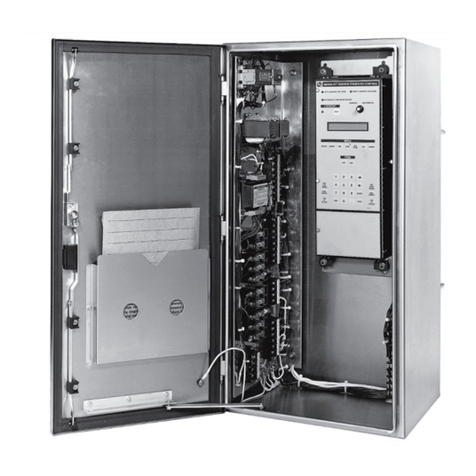
Figure 1. A Micro-AT Source-Transfer Control In a weatherproof enclosure.
The following instructions are for installation, eld programming, and operation of the
Micro-AT Source-Transfer Control In Weatherproof Enclosure. See Figure 1. This control is
designed for use in conjunction with pole-mounted or steel-structure-mounted S&C Alduti-
Rupter®Switches that are power-operated by S&C Switch Operators—Type AS-1A (for
rotating operating mechanisms) or Type AS-10 (for reciprocating operating mechanisms)
equipped for this application. This arrangement provides automatic source transfer for
grounded primary-selective overhead distribution systems rated 7.2 kV through 46 kV.
If already familiar with the Micro-AT control, you may wish to skip these instructions
and just check the quick-reference instructions for changing field-adjustable menu items
contained in Instruction Sheet 515-530.
For instructions on the use of the optional test panel feature for the Micro-AT control
(catalog number suffix “-Y5”), refer to S&C Instruction Sheet 515-505. For instructions
on the use of the optional communications card feature (catalog number suffix “-Y8”),
refer to Instruction Sheet 515-506. For instructions on the use of the Wi-Fi adapter for
applicable Micro-AT controls (kit number TA-3401), refer to Instruction Sheet 515-535.
For installation and operation instructions for the Alduti-Rupter Switches and switch
operators, refer to the specific S&C instruction sheets furnished with those devices.
General

6 S&C Instruction Sheet 515-600
Overview
The Micro-AT Source-Transfer Control in a weatherproof enclosure includes the
following standard features, illustrated in Figure 2 on page 7:
• A MANUAL/AUTOMATIC operation selector switch
• A two-line × 24-character backlit liquid-crystal display
• An automatic-transfer READY indicating lamp, SOURCE-VOLTAGE indicating lamps,
and an overcurrent LOCKOUT indicating lamp with a reset key
• A keypad for entry of the control’s operating characteristics and voltage-, current-,
and time-related operating parameters
• Test keys for simulating overcurrent and loss of voltage on the sources
• Input isolation transformers and a signal-voltage input isolation assembly to isolate
the source-transfer control from potential ground loops—as may occur because of
differences in voltage between the grounding points of the voltage transformers and
the control
• A control-voltage-seeking relay that transfers between the two sources, as required,
to ensure adequate control voltage for the switch operators
• A terminal strip for external connections (All necessary internal connections are
prewired.)
• Fuseholders for secondary fuses of user-furnished voltage transformers
• An unpainted 304L stainless steel NEMA 4X padlockable enclosure for steel structure
mounting

S&C Instruction Sheet 515-600 7
Overview
Figure 2. Close-up of the interior.
Control-voltage-seeking relay
Input isolation transformers
MANUAL/AUTOMATIC
operation selector switch
Two-line × 24-character
backlit liquid-crystal
display
Signal-voltage input
isolation assembly
Instruction manual
Test keys
Keypad
Stainless steel
enclosure
Voltage-transformer secondary fuses and
grounding circuit slugs
Terminal strips for external connections

8 S&C Instruction Sheet 515-600
Overview
The Micro-AT Source-Transfer Control In Weatherproof Enclosure ensures a high
degree of critical-load continuity for primary-selective overhead distribution systems
by minimizing interruptions resulting from the loss of one source. Excluding the inten-
tional time delay to coordinate with upstream protective devices and/or transition dwell
time●, transfer is achieved in 1.5 seconds maximum (when Type AS-1A Switch Opera-
tors are used) or 2.4 seconds maximum (when Type AS-10 Switch Operators are used).
Under normal operating conditions, the preferred-source interrupter switch is closed
and the alternate-source interrupter switch is open. See Figure 3.
The Micro-AT control monitors the condition of both power sources and initiates
automatic loss-of-source transfer switching when preferred-source voltage has been
lost (or reduced below a predetermined level) for a period of time sufficient to confirm
that the loss is not transient. The preferred-source interrupter switch is automatically
opened and the alternate-source interrupter switch is then automatically closed, restor-
ing service to the load.
Following a loss of the preferred source that has resulted in a transfer away from
the preferred-source and then to the alternate-source, the preferred-source interrupter
switch is open and the alternate-source interrupter switch is closed. While in this condi-
tion, if the preferred source voltage meets the criteria for being considered normal but
has not yet been normal for a sufficient period of time to satisfy the return-of-source
time setting and the alternate-source is lost (or reduced below a predetermined level)
for a period of time sufficient to confirm that the loss is not transient, the Micro-AT
control will initiate a loss-of-source transfer. The alternate-source interrupter switch
is automatically opened and the preferred-source interrupter switch is then automati-
cally closed, restoring service to the load.
Both types of loss-of-source transfers in the common-bus primary selective system
are always in “open transition.” The primary reason for the loss-of-source transfer always
being in “open transition” is to best ensure that a fault on the distribution system is not
fed by both sources simultaneously. In addition to the open transition loss-of-source
transfer providing protection for closing both sources into a fault on the distribution
system, the use of the transition dwell time can be made to further minimize the risk
of creating a system fault condition by closing a source interrupter switch to connect
a large motor load with the motor load out of synchronization during completion of a
loss-of-source transfer.
Load
Preferred source Alternate source
S&C Micro-AT Source-Transfer
Control in a weatherproof enclosure S&C Type AS-1A or Type
AS-10 Switch Operator
Figure 3. System diagram, normal configuration.
Voltage
transformer(s)
STC
SOSO
●An adjustable time delay to allow motor residual voltage—the voltage appearing at the terminals of a
connected motor when the source is interrupted—to drop sufficiently before service is restored.
Alduti-Rupter Switch

S&C Instruction Sheet 515-600 9
Overview
●The Unbalance Detection feature should not be programmed in applications using three-phase voltage
sensing provided by two line-to-line connected voltage transformers per source.
Depending on the control settings, return to the normal circuit configuration—
preferred-source interrupter switch closed, alternate-source switch open—may be
performed automatically on restoration of normal voltage to the preferred source after a
delay sufficient to establish that the return is not temporary (Automatic Return mode
or Window Return mode) or manually at a convenient time (Hold Return mode).
In the Automatic Return mode, such return-of-source transfer may be accomplished
with an open transition or a closed transition. With an open transition, retransfer—used
when the power sources are not to be paralleled—the alternate-source interrupter
switch opens before the preferred-source interrupter switch closes... with a momentary
interruption of service to the load. With a closed transition, retransfer—selected when
it is permissible to parallel the sources so that there will be no interruption of service to
the load—the alternate-source interrupter switch will open after the preferred-source
interrupter switch closes.
The Window Return mode is functionally identical to the Automatic Return mode,
except that return-of-source transfer is permitted to occur only if the time of day is within
a user-specified time “window,” typically at a time when the implications are least severe
for critical loads.
In Hold Return mode, if the preferred source voltage meets the criteria for being
considered normal and if the alternate-source is lost (or reduced below a predetermined
level) for a period of time sufficient to confirm that the loss is not transient, an automatic
open transition loss-of-source transfer will take place so that the load is served from the
preferred-source following the loss-of-source transfer.
The voltage-sensing input circuitry of the Micro-AT Source-Transfer Control In
Weatherproof Enclosure accommodates either of the following single-phase or three-
phase voltage-sensing schemes, using user-furnished voltage transformers having
240/120-Volt, 60-Hertz secondaries:
• For single-phase sensing, one line-to-ground or line-to-line connected voltage trans-
former per source
• For three-phase sensing, three line-to-ground connected voltage transformers per
source or—on delta-connected systems only—two line-to-line connected voltage
transformers per source
In instances where three-phase source voltage sensing is used, an output-voltage
magnitude unbalance and/or phase-angle unbalance will likely exist between the voltage
transformers on each source. The Micro-AT control must be normalized to compensate
for such differences on the left source and the right source, respectively. A source can
be normalized only if each phase has measurable voltage and its sequence of rotation is
the same as on the other source.
The base voltages on phase 2 of the left and right sources can also be calibrated to
known values.
An Unbalance Detection feature may be eld-programmed in the Micro-AT control in
instances where three-phase voltage sensing is provided by three line-to-ground
connected voltage transformers per source. This feature protects the loads from
any source-side open-phase condition at the same system voltage level as the S&C
Alduti-Rupter Switches—whether caused by utility-line burndown, broken conductors,
single-phase switching, equipment malfunctions, or single-phasing resulting from blown
source-side fuses. The unbalance detection feature continuously develops and monitors
the negative-sequence and zero-sequence voltages to detect any unbalance present as
the result of an open-phase condition●.
If the voltage unbalance exceeds a preset reference level for a period of time
sufficient to confirm that the loss is not transient, the Micro-AT control will initiate an
automatic loss-of-source transfer to the other source. By monitoring negative-sequence
and zero-sequence voltages, the unbalance detection feature detects virtually all source-
side open-phase conditions, even those where backfeed defeats simple voltage-magnitude
sensing schemes.
Voltage Sensing
Unbalance Detection

10 S&C Instruction Sheet 515-600
Overview
An Overcurrent Lockout feature may be optionally furnished in the Micro-AT Source-
Transfer Control In Weatherproof Enclosure. This feature prevents an automatic-transfer
operation that would close a source interrupter switch into a fault, thereby avoiding
further utility-system disturbance. The Overcurrent Lockout feature requires three
user-furnished Fisher Pierce Series 1301 Powerex® Line Post Current Sensors for each
source.
An overcurrent in excess of a preset level will set up the lockout feature. If the over-
current is due to a fault cleared by a source-side protective device, the prolonged loss
of voltage will cause the associated source interrupter switch to open. At the same
time, a lockout mode will be set up in the source-transfer control so the other source
interrupter switch will not automatically close into the fault. (If the overcurrent is due
to a fault cleared by a load-side protective device, however, there will be no
prolonged loss of voltage, so the source-transfer control will not initiate any switching
operations.)
To prevent nuisance lockouts resulting from reclosing operations by source-side
circuit breakers, the Overcurrent Lockout feature includes a magnetizing-inrush current
restraint scheme. Upon loss of source voltage or, if the Unbalance Detection feature is
programmed, upon voltage unbalance exceeding a preset reference level for 5 cycles, the
magnetic inrush current restraint scheme is initiated for a period of 2 minutes. During the
period of magnetic inrush current restraint scheme activation 1 second is added to the
overcurrent pickup delay setting duration, adjustable from 3 to 100 milliseconds. Unless
an overcurrent condition exists that is greater than the 1 second plus overcurrent pickup
delay duration, the magnetic inrush current restraint scheme remains in effect for 2 min-
utes immediately subsequent to the initial loss of voltage. The magnetic inrush current
restraint scheme prevents pickup of the Overcurrent Lockout feature due to transformer
magnetizing-inrush current that can be experienced during upstream recloser activity.
The lockout mode may be externally reset; a terminal block is included in the
weatherproof enclosure for attachment of user-furnished control wiring providing the
appropriate reset signal.
A Remote Indication feature may also be optionally furnished in the Micro-AT Source-
Transfer Control In Weatherproof Enclosure. This feature permits remote monitoring of
presence or absence of source voltages, manual or automatic operating mode, status of
the READY indicator, EVENT indicator, and (if furnished) overcurrent lockout. A terminal
block is included in the weatherproof enclosure for attachment of user-furnished control
wiring to remote indicators.
A Test Panel feature may also be optionally furnished. This feature permits the use of
an external, adjustable three-phase source to verify, through independent measurement,
the response of the control to Loss-of-Source, Phase Unbalance, and Overcurrent
Lockout conditions.
A Supervisory Control feature may be optionally furnished as well. This feature
permits switch operation and Micro-AT operating mode control from a remote location. A
terminal block is included in the weatherproof enclosure for attachment of user-
furnished control wiring providing the appropriate supervisory control signals.
A Communications Card feature may be optionally furnished as well. This feature is
used in conjunction with a user-furnished personal computer●for local uploading of the
Micro-AT control’s “events,” operating characteristics and operating parameters, digital
input and output states, and messages explaining why the automatic-transfer READY
indicating lamp isn’t lighted. This feature also allows local downloading of the user’s
standard operating parameters to the Micro-AT control.
A Micro-AT control communication cable is necessary for connecting the communi-
cations card to the personal computer. Refer to the “Accessories” table in Specification
Bulletin 515-31.
For Micro-AT control users with Windows 10, 64-bit operating system platforms, a
Wi-Fi adapter kit (catalog number TA-3401) in tandem with the HMI application software
can be used to locally connect to the Micro-AT control.
To obtain the HMI software application, go to sandc.com/en/support/sc-customer-
portal/ and download the Micro-AT control HMI application software installer.
●Requires a Windows® 95, 98, 2000, NT, XP, or Windows 7 32-bit operating system. A Windows 7 64-Bit
Operating System must be run in XP mode (only available for Professional and Ultimate Operating Systems).
Overcurrent Lockout
Remote Indication
Test Panel
Supervisory Control
Communications Card
Wi-Fi Adapter Kit
S&C Instruction Sheet 515-600 11
Operating Description
●Factory-set at 85.0 Volts.
■Factory-set at 2.00 seconds.
▲Factory-set at 105 Volts.
◆Factory-set at 3.00 minutes.
With adequate voltage available from both utility sources, the preferred-source interrupter
switch should be closed and the alternate-source interrupter switch should be open with
its associated circuit available as a standby. The manual/automatic operation selector
switch should be set to Automatic mode and—if the Supervisory Control option is
enabled—the supervisory manual/automatic dry contact is closed and the left source
voltage, right source voltage, and automatic-transfer READY indicating lamps should
be lit. See the “Conditions required to light automatic-transfer READY indicating lamp”
section on page 32.
At installations using single-phase source voltage sensing, the Micro-AT control
continuously monitors the signal-input voltage level on phase 2 of each of the two sources
and compares these inputs to the predetermined reference level to determine the status of
each source. The control will initiate a loss-of-source transfer when each of the following
conditions exist:
• The signal-input voltage from phase 2 of the source serving the load is reduced below
the predetermined loss-of-source voltage setting●,for a period of time considered
sufcient to conrm the condition is not transient—the predetermined loss-of-source
time setting■
• The signal-input voltage from phase 2 of the standby source exceeds the predetermined
return-of-source voltage setting▲
• The Overcurrent Lockout feature, if programmed, is not “set up” to prevent an auto-
matic transfer operation that would close a source interrupter switch into a fault (See
the “Overcurrent Lockout Condition” section on page 12.)
At installations using three-phase source voltage sensing, the Micro-AT control con-
tinuously monitors the signal-input voltage level on each phase of the two sources and
compares these inputs to the predetermined reference level to determine the status of
each source. The control will initiate a loss-of-source transfer when each of the follow-
ing conditions exist:
• The signal-input voltage from one or more phases of the source serving the load is
reduced below the predetermined loss-of-source voltage setting●for a period of time
considered sufcient to conrm the condition is not transient—the predetermined
loss-of-source time setting■
• The signal-input voltages from all three phases of the standby source exceed the pre-
determined return-of-source voltage setting▲
• The Overcurrent Lockout feature, if programmed, is not “set up” to prevent an auto-
matic transfer operation that would close a source interrupter switch into a fault (See
the “Overcurrent Lockout Condition” section on page 12.)
In addition, at installations using three-phase source voltage sensing, if the Unbalance
Detection feature is programmed, the control will initiate a transfer as a result of an
open-phase condition when the system unbalance exceeds the predetermined unbalance-
detection voltage. See the “Transfer on Unbalance Condition” section on page 12.
If a loss-of-source transfer occurs, the automatic-transfer READY indicating lamp will
extinguish—indicating the normal condition no longer exists.
Upon return of preferred-source voltage for a period of time sufcient to establish
that the return is not temporary—the predetermined return-of-source time setting◆,
automatic return-of-source transfer to the normal condition will occur if the control
has been programmed for Automatic Return mode. The return-of-source transfer will
either be a “closed transition” or an “open transition,” depending on the control settings.
With a “closed transition” return, the preferred-source interrupter switch will close
before the alternate-source interrupter switch is opened, so that there is no interruption
of service to the load. With an “open transition” return, which prevents an automatic
operation that would parallel the power sources, the alternate-source interrupter switch
will open prior to closing of the preferred-source interrupter switch.
Normal Condition
Transfer on
Loss-of-Source
Voltage
Transfer on Return-of-
Source Voltage

12 S&C Instruction Sheet 515-600
Operating Description
If the control has been programmed for “window return,” automatic return-of-source
transfer to the normal condition will be performed in the same manner as for an “auto-
matic return.” But return-of-source transfer is permitted to occur only if the time of day
is within the specified time “window.” The beginning of this window is the predetermined
Window Begin setting;●the window length is adjustable from 1 minute to 3 hours.
If the control has been programmed for “hold return,” transfer to the normal condition
must be accomplished manually—unless alternate-source voltage becomes inadequate
and preferred-source voltage is adequate. In this case of loss of alternate-source voltage,
an automatic “open transition” loss-of-source transfer will take place.
When the return-of-source transfer occurs, the automatic-transfer READY indicating
lamp will again light, indicating that the normal condition has been restored.
At installations using three-phase source voltage sensing, the control may be programmed
to detect phase unbalance conditions on the source. This feature protects the loads from
any source-side open-phase condition at the same system voltage level as the Alduti-Rupter
Switches—whether caused by utility-line burn-down, broken conductors, single-phase
switching, equipment malfunctions, or single-phasing resulting from blown source-side
fuses.■
When this feature has been programmed, the control will initiate an automatic source
transfer when each of the following conditions exist:
• The signal-input phase-voltage unbalance of the source serving the load exceeds the
predetermined unbalance-detect voltage,▲for a period of time considered sufcient
to conrm the condition is not transient—the predetermined Loss-Of-Source Time
setting◆
• The signal-input phase-voltage unbalance of the standby source is less than the pre-
determined unbalance-detection voltage▲
• The Overcurrent Lockout feature, if programmed, is not “set up” to prevent an
Automatic Transfer operation that would close a source interrupter switch into a
fault. See the “Overcurrent Lockout Condition” section below
Upon return of the preferred-source phase voltages to their normal, balanced state,
return to that source can be accomplished as described in the “Transfer on Return of
Source Voltage” section on page 11.
At installations where three user-furnished Fisher Pierce Series 1301 Powerex Line Post
Current Sensors have been provided on each source, the control may be programmed to
include an Overcurrent Lockout feature. This feature prevents an automatic-transfer
operation that would close a source interrupter switch into a fault, thereby avoiding
further utility-system disturbances.
An overcurrent in excess of the predetermined Lockout Level setting▼ detected as
the imbalance in the three-phase current—the summation of the currents sensed by the
individual phase current sensors of the source serving the load—will “set up” the Lockout
feature. The LOCKOUT lamp will light.
Transfer on Unbalance
Condition
Overcurrent Lockout
Condition
●Factory-set at 01:00 (24-hour format).
■The Unbalance Detection feature should not be programmed in applications using three-phase voltage
sensing provided by two line-to-line connected voltage transformers per source.
▲Factory-set at 18 Volts.
◆Factory-set at 2.00 seconds.
▼Factory-set at 1200 amperes. S&C recommends customers use the factory-default setting or adjust this
value to 70% of the available neutral fault current, whichever is lower. In some applications, the lockout level
setting is determined by the setting of user-furnished external relaying. An adjustable overcurrent-lockout
pickup time delay is provided to prevent nuisance lockouts due to motor load backfeed into upstream faults.
Factory-set at 50 milliseconds. Adjustment range is 3 to 100 milliseconds.

S&C Instruction Sheet 515-600 13
Operating Description
If the overcurrent is due to a fault that is cleared by a source-side protective device,
the prolonged loss of source voltage will cause the associated source interrupter switch
to open, and the Overcurrent Lockout feature will prevent the other source interrupter
switch from closing into the fault.
After the fault has been located and repaired, the manual/automatic operation selec-
tor switch must be set in Manual mode and the RESET key pressed to cancel the lockout
condition, which will extinguish the LOCKOUT lamp.
Service to the load can then be restored by pressing the CLOSE pushbutton on the
preferred-source interrupter switch operator. If, however, voltage is not available on the
preferred source, service to the load can be restored by pressing the CLOSE pushbutton
on the alternate-source interrupter switch operator. After the source interrupter switch
has closed, the manual/automatic operation selector switch should be placed in the
Automatic setting. If the normal condition has been restored, the automatic-transfer
READY indicating lamp will light.
If the overcurrent is due to a fault that is cleared by a load-side protective device, no
switching will occur because loss-of-source voltage is not of sufficient duration to ini-
tiate opening of the source interrupter switch serving the load. In this case, although the
fault current initially “sets up” the Lockout feature (and the LOCKOUT lamp lights), the
subsequent return of normal source voltage will actuate the lockout-reset time delay●.
After this predetermined time delay, the Lockout feature will automatically reset and
the control will return to its normal state and the LOCKOUT lamp will extinguish.
●Factory-set at 20.0 seconds.

14 S&C Instruction Sheet 515-600
Installation
Complete the following steps to install the Alduti-Rupter Switches, switch operators, and
Micro-AT Source Transfer Control:
STEP 1. Install the S&C Alduti-Rupter Switches and Type AS-1A or Type AS-10 Switch
Operators in accordance with the S&C instruction sheets and erection
drawings furnished with those devices. Also install the voltage transformers
and, if the Overcurrent Lockout feature has been specied, the current
sensors in accordance with the instructions provided by the suppliers of those
devices.
STEP 2. If the source-transfer control enclosure is to be pole-mounted by means
of the optional pole-mounting bracket (catalog number sufx “-P1”),
perform the following:
(a) Drill two -inch (17-mm) diameter holes 9⅜inches (238 mm) apart in the
center of the utility pole at the desired height for mounting the enclosure.
(b) Insert two 5/8-inch diameter through-bolts (not furnished) in the holes just
drilled. Secure these bolts loosely with the necessary washers and nuts in
such a manner the heads of the bolts project sufciently (approximately 3
inches (76 mm) from the face of the pole) to engage the pole mounting
bracket.
(c) Attach two eyebolts (not furnished) to the holes provided at the top of the
enclosure mounting frame. See Figure 4 on page 15. Securely tighten the
eyebolts. Attach two suitable lifting slings to the eyebolts and slowly raise
the slings so they become taut. Carefully raise the enclosure to its mounting
level and guide it so the through-bolts projecting from the utility pole slip
into the two keyholes in the pole mounting bracket. Lower the enclosure
slightly so it bears on the through-bolts. Fully tighten the through-bolts,
making sure the washer for each bolt is between the bolt head and the pole
mounting bracket. Proceed to Step 3.
If the source-transfer control enclosure is to be steel-structure-mounted:
Attach two eyebolts (not furnished) to the holes provided at the top of the enclo-
sure mounting frame. See Figure 4 on page 15. Securely tighten the eyebolts.
Attach two suitable lifting slings to the eyebolts and slowly raise the slings
so they become taut. Carefully raise the enclosure to its mounting level and
securely bolt it in place.
STEP 3. Ground the enclosure by solidly connecting one number 6 AWG wire (or wires
ofequivalentcross-sectionalarea)tothegroundlugonthebackofthe enclosure.
See Figure4 on page 15.
NOTICE
Failure to use proper-size ground wire may result in damage to the source-transfer
control.

S&C Instruction Sheet 515-600 15
Installation
STEP 4. Remove the voltage-transformer secondary fuses and grounding circuit slugs
from the source-transfer control enclosure. See Figure 2 on page 7 for location
of these components.
STEP 5. Prepare a weather-tight entrance in the bottom of the enclosure in accordance
with user’s practice. Install conduit and interconnection wiring between the
source-transfer control, the switch operators, the voltage transformers, and
the current sensors (as appropriate) in accordance with the system wiring
diagram and the interconnection wiring diagram furnished with the source-
transfer control. Then, replace the fuses and slugs removed in Step 4.
STEP 6. If three-phase voltage sensing is provided by two line-to-line connected
voltage transformers per source:It will be necessary to reposition the input
plug on the voltage-input isolation assembly. Remove the input plug from
Receptacle N and insert it in Receptacle V. See Figure 5.
Input plug in
Receptacle N
Receptacle V
Voltage-transformer
secondary fuse
Figure 5. Removing voltage-transformer secondary fuses
and grounding circuit slugs and repositioning the input
plug on the voltage-input isolation assembly.
Mounting frame
Pole
mounting
bracket
(catalog
number
suffix “-P1”)
Ground
lug
Figure 4. Hoisting the enclosure into position.
Lifting slings Eyebolts
(not furnished)
suffix “-P1”)

16 S&C Instruction Sheet 515-600
Features
The Micro-AT Source-Transfer Control uses an advanced electronic microprocessor
to perform control operations, as directed by settings programmed into the device at the
factory and in the field. Such settings—consisting of the control’s operating characteris-
tics and voltage-, current-, and time-related operating parameters—are entered into the
control by means of a keypad on the front panel. See Figure 6 on page 17.
To simplify entry of this information and to permit its quick review on the liquid-crystal
display, the operating characteristics have been grouped together as a series of “items”
in the Configure menu. Similarly, the voltage-, current-, and time-related operating
parameters have been grouped together as a series of items in the Voltage, Current, and
Time menus, respectively. A particular item can be accessed for display by first pressing
the appropriate menu key and then scrolling through the items, using the NEXT or LAST
item key. To prevent unauthorized changes to the operating characteristics and operating
parameters, each item is protected by an access code; the correct access code must be
entered before the item can be altered.
The Test menu provides the means for checking the functioning of the source-transfer
control and is also used to enable the test keys for simulating overcurrent and/or loss of
voltage on the sources.
The Micro-AT control features powerful built-in diagnostic tools. The control auto-
matically records system status and the status of the device’s controller circuits every
time a control operation occurs. Each such operation, referred to as an “event,” is
indicated by the illumination of a lamp on the Event menu key and is available for dis-
play under this menu. Further, the control has available for display, as items under the
Examine menu, the present source voltage and current inputs, and the present status
of discrete inputs to and outputs from the control.
The liquid-crystal display provides the means for viewing the operating characteristics
and operating parameters which have been programmed into the control as items in the
Congure, Voltage, Current, and Time menus, entries in the Event menu, and present
system and control states in the Examine menu.
The display normally appears like this:
EEDATEEEE EEEEEEEEEEEEETIME
PRESSEANYEMENUEKEY
If a menu key is pressed—for example, the VOLTAGE menu key—the display changes to:
VOLTAGE:
PRESS LAST/NEXT ITEM
If the NEXT item key is then pressed, the first item in the menu—in this case, loss-
of-source voltage— appears.
VOLTS: ELOSSEOFESOURCEE
E8 5 . 0EVOLTSEEEEEEEECHANGE
In this example, the display is indicating that the present value of loss-of-source voltage
programmed into the control is 85.0 volts. The Change message in the lower right-hand
corner of the display indicates that the value of loss-of-source voltage can be changed.
If a change to the present value of loss-of-source voltage is desired, the manual/
automatic operation selector switch must first be placed in Manual mode Then, if the
CHANGE key is pressed, the following display appears:
VOLTS: LOSS OF SOURCE
ENTER ACCESS CODE
The Display

S&C Instruction Sheet 515-600 17
Features
Figure 6. A Close-up of the front panel features.
LEFT SOURCE
VOLTAGE
indicating lamp
AUTOMATIC-TRANSFER
READY indicating lamp
TEST keys for simulating
overcurrent and loss of
voltage on left source
TEST keys for simulating
overcurrent and loss of
voltage on right source
RIGHT SOURCE VOLTAGE
indicating lamp
MANUAL/AUTOMATIC
operation selector switch
Two -line ×24-character backlit
liquid-crystal display (LCD)
Menu keys
Keypad
LAST and NEXT item keys
Overcurrent LOCKOUT
indicating lamp and RESET
key

18 S&C Instruction Sheet 515-600
Features
The display is indicating the access code must be entered before the value of loss-
of-source voltage can be changed. As each digit of the access-code number is pressed,
the display indicates that digit. When all the digits have been pressed—followed by the
ENTER key—the display changes to:
VOLTS: LOSS OF SOURCE
8 5 .0 VOLTS
The desired value of loss-of-source voltage can be entered at this time. If a value of 102
Volts were desired, the “1,” “0,” and “2” keys would be pressed—followed by the ENTER
key. The display changes to:
VOLTS: LOSS OF SOURCE
102 VOLTS CHANGE
Other items in the Voltage menu are accessed by use of the NEXT item key (or LAST
item key) and changed, if necessary, in the same manner. The access code need not be
reentered. When no further items are to be accessed in the Voltage menu, the NEXT key
should be pressed and then the QUIT key should be pressed.
Items in other menus are similarly accessed by pressing the appropriate menu key,
followed by the NEXT item key (or LAST item key) and exited gracefully by pressing
the QUIT key. Following completion of the changes to the various settings, the manual/
automatic operation selector switch placed in Automatic mode.
DATE TIME
PRESS ANY MENU KEY
Incidentally, the display will also revert to its normal appearance if no keystrokes of
the keypad have been detected for 5 minutes. Should this occur, the access code will
need to be reentered before the value of an item can be changed.
If an invalid access code is entered in the course of changing the value of an item, an
Error message will be displayed for 5 seconds. For the example given above, this display
would appear as follows:
VOLTS: LOSS OF SOURCE
INVALID ACCESS CODE
If an unacceptable value (one not within the specified range) is entered in the course
of changing the value of an item, another Error message will be displayed for 5 seconds.
For the example given above, this display would appear as follows:
ENTRY MUST BE BETWEEN
80.0 AND 105 VOLTS
Error Messages

S&C Instruction Sheet 515-600 19
Features
A few field changeable items in the Configure menu require a non-numeric
response. In such instances, the display will be similar to this:
CONFIG: SELECT TRANSITION
OPEN CHANGE
Here the display is indicating the Open option has been selected as the type of transi-
tion by which an automatic return-of-source transfer will be effected. The Change mes-
sage in the lower right-hand corner of the display indicates this selection can be changed.
If a change is desired, the access code will need to be entered in the same manner
described above.
After the access code has been entered, pressing the “ ” or “ ” key will display
the other possible selection(s): in this case, “CLOSED.” The ENTER key must be pressed
to accept the selection of “CLOSED” transition.
The display will now look like this:
CONFIG: SELECT TRANSITION
CLOSED CHANGE
Some items are available only for display of information. One such item, in the
Voltage menu, is left-source phase 2 voltage. The display will be similar to this:
VOLTS: LEFT PHASE 2
118 VOLTS MENU/ITEM
Here the display is indicating that the actual voltage on left-source phase 2 is
118 Volts. The Menu/Item message in the lower right-hand corner of the display
indicates that a menu key, the NEXT item key, or LAST item key can be pressed to exit
this particular menu item.
Non-Numeric
Items
Read-Only Items

20 S&C Instruction Sheet 515-600
Field Adjustment and Programming
To operate properly, the Micro-AT Source-Transfer Control must be correctly
programmed. Some menu items have been factory-set and cannot be field-adjusted●.
Some menu items have factory-settings but can be field-adjusted. Still other menu items
must be field-adjusted.
Notes: Be sure to check each field-adjustable item in the Configure, Voltage,
Current, and Time menus in the manner described below. The factory settings for
these items may not all be appropriate for a particular installation.
To perform the field-adjustment and programming procedures outlined in this docu-
ment, enter the correct access-code number when directed.
The access-code number is 6601.
Notes:
• To ensure any changes to the factory settings in all menus are stored in memory, press
the NEXT item key before the QUIT key.
• Always normalize the left and right sources and set the base voltages on Phase 2 of
the left and right sources after executing CONFIG: RESTORE VALUES.
• When changing Select Bus Type setting or the Select Preferred setting in the Con-
gure menu, the Micro-AT control will power down and reboot. A “System Startup”
will be recorded in the event log.
●Non-field-adjustable items in the Configure and Voltage menus are listed in the “Appendix” on page 38.
Other manuals for Micro-AT
3
Table of contents
Other S&C Controllers manuals

S&C
S&C 6800 Series User manual

S&C
S&C IntelliCap Plus Operating instructions

S&C
S&C 6802 User guide

S&C
S&C Micro-AT User manual

S&C
S&C Vista SD Owner's manual

S&C
S&C PMH Operation and maintenance manual

S&C
S&C Vista SD Owner's manual

S&C
S&C 5800 Series Operating instructions

S&C
S&C BankGuard PLUS Manual

S&C
S&C Micro-AT User manual

S&C
S&C IntelliCap User manual

S&C
S&C PMH Installation instructions

S&C
S&C IntelliCap Plus User manual

S&C
S&C IntelliCap Instruction Manual

S&C
S&C BankGuard PLUS User manual

S&C
S&C GridMaster User manual

S&C
S&C 6800 Series Parts list manual

S&C
S&C 5800 Series User manual

S&C
S&C BankGuard PLUS Instruction Manual

S&C
S&C Micro-AT Instruction Manual