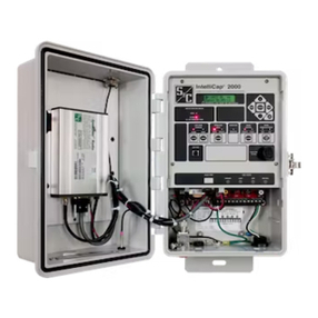
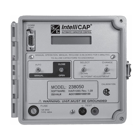
S&C IntelliCap User manual

S&C IntelliCap®Automatic Capacitor Control
Instruction Sheet 1022-510
© S&C Electric Company 2003-2017, all rights reserved
December 4, 2017
Installation
Table of Contents
Section Page Section Page
Introduction
Qualified Persons .............................2
Read this Instruction Sheet ......................2
Retain this Instruction Sheet .....................2
Proper Application .............................2
Special Warranty Provisions .....................2
Safety Information
Understanding Safety-Alert Messages .............4
Following Safety Instructions .....................4
Replacement Instructions and Labels ..............4
Safety Precautions ............................5
Installation
Applicable Software ............................6
Pre-Installation Checklist ........................6
Optional In-Shop Setup .........................6
Installing the Current Sensor (var only) .............7
Onsite Installation..............................9
Meter Base Mounting ..........................10
Bracket Mounting .............................14
Testing Capacitor Bank Operation ................17
Setting the Control for Manual Operation ..........17
Wiring Diagrams ..........................18
NOTICE
The latest instruction sheets are posted as PDF files at sandc.com/en/support/product-literature/.IntellCap software
can be downloaded at sandc.com/en/support/sc-customer-portal/.If you need assistance, please contact GSMC@
sandc.com or call (888) 762-1100.

2S&C Instruction Sheet 1022-510
Introduction
WARNING
The equipment covered by this publication must be installed, operated, and main-
tained by qualified persons who are knowledgeable in the installation, operation, and
maintenance of overhead electric power distribution equipment along with the
associated hazards.
A qualified person is one who is trained and competent in:
• The skills and techniques necessary to distinguish exposed live parts from nonlive
parts of electrical equipment
• The skills and techniques necessary to determine the proper approach distances
corresponding to the voltages to which the qualified person will be exposed
• The proper use of the special precautionary techniques, personal protective
equipment, insulating and shielding materials, and insulated tools for working on or
near exposed energized parts of electrical equipment
These instructions are intended only for such qualified persons. They are not intended
to be a substitute for adequate training and experience in safety procedures for this type
of equipment.
NOTICE
Read this instruction sheet thoroughly and carefully before installing or operating your
S&C IntelliCap Automatic Capacitor Control. Familiarize yourself with the Safety Infor-
mation on page 4 and Safety Precautions on page 5. The latest version of this publication
is available online in PDF format at sandc.com/en/support/product-literature/.
This instruction sheet is a permanent part of your S&C IntelliCap Automatic Capacitor Control.
Designate a location where you can easily retrieve and refer to this publication.
WARNING
The equipment in this publication must be selected for a specific application.
The application must be within the ratings furnished for the selected equipment.
The standard warranty contained in S&C’s standard conditions of sale, as set forth in Price
Sheets 150 and 181, applies to the S&C IntelliCap Automatic Capacitor Control, except that
the rst paragraph of the said warranty is replaced by the following:
(1) General: The seller warrants to the immediate purchaser or end user for a period of
10 years from the date of shipment that the equipment delivered will be of the kind and quality
specified in the contract description and will be free of defects of workmanship and material.
Should any failure to conform to this warranty appear under proper and normal use within 10
years after the date of shipment, the seller agrees, upon prompt notification thereof and con-
firmation that the equipment has been stored, installed, operated, inspected, and maintained
in accordance with the recommendations of the seller and standard industry practice, to cor-
rect the nonconformity either by repairing any damaged or defective parts of the equipment
or (at the seller’s option) by shipment of necessary replacement parts. The seller’s warranty
does not apply to any equipment that has been disassembled, repaired, or altered by anyone
other than the seller. This limited warranty is granted only to the immediate purchaser or,
if the equipment is purchased by a third party for installation in third-party equipment, the
end user of the equipment. The seller’s duty to perform under any warranty may be delayed,
at the seller’s sole option, until the seller has been paid in full for all goods purchased by the
immediate purchaser. No such delay shall extend the warranty period.
Replacement parts provided by the seller or repairs performed by the seller under the war-
ranty for the original equipment will be covered by the above special warranty provision for
its duration. Replacement parts purchased separately will be covered by the above special
warranty provision.
Qualified Persons
Read this
Instruction Sheet
Retain this
Instruction Sheet
Proper Application
Special Warranty
Provisions

S&C Instruction Sheet 1022-510 3
Introduction
Warranty of the S&C IntelliCap Automatic Capacitor Control is contingent upon the instal-
lation, configuration, and use of the control or software in accordance with S&C’s applicable
instruction sheets.
This warranty does not apply to major components not of S&C manufacture. However,
S&C will assign to the immediate purchaser or end user all manufacturer’s warranties that
apply to such major components.
Warranty of equipment/services packages is contingent upon receipt of adequate informa-
tion on the user’s distribution system, sufficiently detailed to prepare a technical analysis.
The seller is not liable if an act of nature or parties beyond S&C’s control negatively impact
performance of equipment/services packages; for example, new construction that impedes
radio communication, or changes to the distribution system that impact protection systems,
available fault currents, or system-loading characteristics.

4S&C Instruction Sheet 1022-510
Safety Information
Understanding
Safety-Alert Messages
Following
Safety Instructions
Replacement
Instructions and
Labels
Several types of safety-alert messages may appear throughout this instruction sheet and on
labels attached to the S&C IntelliCap Automatic Capacitor Control. Familiarize yourself with
these types of messages and the importance of these various signal words:
DANGER
“DANGER” identifies the most serious and immediate hazards that will likely result in
serious personal injury or death if instructions, including recommended precautions,
are not followed.
WARNING
“WARNING” identifies hazards or unsafe practices that can result in serious personal
injury or death if instructions, including recommended precautions, are not followed.
CAUTION
“CAUTION” identifies hazards or unsafe practices that can result in minor personal
injury if instructions, including recommended precautions, are not followed.
NOTICE
“NOTICE”identifies important procedures or requirements that can result in product or
property damage if instructions are not followed.
If you do not understand any portion of this instruction sheet and need assistance,
contact your nearest S&C Sales Office or S&C Authorized Distributor. Their tele-
phone numbers are listed on S&C’s website sandc.com Or call S&C Headquarters
at (773) 338-1000; in Canada, call S&C Electric Canada Ltd. at (416) 249-9171.
NOTICE
Read this instruction sheet thoroughly and
carefully before installing or operating your S&C
IntelliCap Automatic Capacitor Control.
If you need additional copies of this instruction sheet, contact your nearest S&C Sales Ofce,
S&C Authorized Distributor, S&C Headquarters, or S&C Electric Canada Ltd.
It is important that any missing, damaged, or faded labels on the equipment be replaced
immediately. Replacement labels are available by contacting your nearest S&C Sales Office,
S&C Authorized Distributor, S&C Headquarters, or S&C Electric Canada Ltd.

S&C Instruction Sheet 1022-510 5
Safety Precautions
DANGER
The S&C IntelliCap Automatic Capacitor Control line voltage input range is 93 to 276
Vac. Failure to observe the precautions below will result in serious personal injury
or death.
Some of these precautions may differ from your company’s operating procedures and
rules. Where a discrepancy exists, follow your company’s operating procedures and rules.
1. QUALIFIED PERSONS.Access to the IntelliCap
Automatic Capacitor Control must be restricted only to
Qualified Persons.
2. SAFETY PROCEDURES. Always follow safe operating
procedures and rules. Always maintain proper clearance
from energized components.
3. PERSONAL PROTECTIVE EQUIPMENT. Always use
suitable protective equipment, such as rubber gloves,
rubber mats, hard hats, safety glasses, arc-flash
clothing, and fall protection, in accordance with safe
operating procedures and rules.
4. SAFETY LABELS AND TAGS. Do not remove or
obscureanyofthe“DANGER,”“WARNING,”“CAUTION,”
or “NOTICE” labels and tags. Remove tags ONLY if
instructed to do so.
5. MAINTAINING PROPER CLEARANCE.Always
maintain proper clearance from energized components.

6S&C Instruction Sheet 1022-510
Applicable Software
This instruction sheet was prepared for use with IntelliCap
software: ICAP109S and I VA R10 9 S.
Software identification is shown on the IntelliLink®Setup
Software Troubleshooting>Control & Switch Information
screen. For questions regarding the applicability of informa-
tion in this instruction sheet to future product releases, please
contact S&C Electric Company.
Pre-Installation Checklist
Before installing the IntelliCap control, carry out the following
steps in the shop:
STEP 1. Inspect the control for visible damage.
Make sure there is no obvious damage to the
control enclosure or any internal components.
STEP 2. Check whether a sensor cable may be needed.
With var sensing, the control may require a
connection cable for the sensors.
STEP 3. Use the required setup software and equipment.
It is possible to use the faceplate switches
and LCD screen for initial setup of an IntelliCap
control, but using IntelliLink software is easier
and faster. The faceplate switches can be used for
later adjustments in the eld. Equipment needed
includes:
• A personal computer The computer should
have a Microsoft Windows®7 or 10 operating
system, Internet Explorer 5.0 or higher, 32 MB of
RAM, a USB or serial port, and Internet access to
the S&C Automation Customer Support Portal.
• A serial communication cable This cable
connects the computer to the LOCAL COMM
PORT on the control. Use a straight-through
cable, not a null-modem cable. The cable must
be long enough to connect to an installed
IntelliCap control.
The serial connection is RS232 with a
DB9-pin connector.
If the computer only has USB ports, use a
serial-to-USB cable adapter.
STEP 4. Do one of the following:
• Go to the installation site and install the
IntelliCap control. Then congure the control
as described in Instruction Sheet 1022-530, ”S&C
IntelliCap®Automatic Capacitor Control: Setup.”
• Complete the conguration steps summarized
in the “Optional In-Shop Setup” section while
you are in the shop. Then install the control at
the site.
Optional In-Shop Setup
The following steps can be completed while you are still in
the shop or later at the installation site:
STEP 1. Install the IntelliLink software on your computer.
For details, see the “Install the IntelliLink
Software” section in Instruction Sheet 1022-530,
“S&C IntelliCap®Automatic Capacitor Control:
Setup.”
STEP 2. Congure the control software.
Most of the software setup can be done in the
shop. For an explanation of how to configure
the software, see the “Setting Up the Capacitor
Control” section in Instruction Sheet 1022-530, S&C
IntelliCap®Automatic Capacitor Control: Setup.”
Installation

S&C Instruction Sheet 1022-510 7
Installing the Current Sensor (var only)
The IntelliCap with Var control uses the phase-angle
relationship between the voltage waveform of the 120-Vac
control power source and the current waveform from the
current sensor. Calculations will be incorrect if the control-
power source is not connected to the feeder being monitored
for current.
Other factors that may also affect accuracy:
• To achieve the most accurate var-calculation results,
power the control with a dedicated potential transformer
(PT) that has at least one leg connected to the same phase
as the current sensor.
• The PT supplying control power to the control may be
connected phase to phase or phase to ground. Either
connection can be congured in the setup software.
• When the control is powered from an adjacent secondary,
the phase angle may be affected slightly. The calculated
var level may also be changed by a few percentage points,
depending on the secondary loading and its associated
voltage reduction. With this wiring conguration, voltage-
override logic will not have effective control of the primary
feeder voltage.
• Because calculations are based on single-phase current,
balanced three-phase currents or loads will produce the
best results. Current measurements at the time of instal-
lation may help to decide the best phase to monitor if the
feeder is signicantly unbalanced.
• Install the current sensor on the source side of the
capacitor bank connection. See Figure 1 on page 8. The
source side is the side nearest the substation during
normal operation. The control will then measure the effect
of the capacitor bank on power factor when the bank is
switched in.
• Signal polarity reversal can be congured in the setup
software.
• Ground the sensor base at the top of the pole.
• With S&C and Lindsey line-post current Sensors, the signal
wires are shielded, and the shield must be grounded at the
IntelliCap control for safety.
• We recommend that a Lindsey current sensor be installed
with a permanent current-sensor choke. This eliminates
the need for eld calibration and ensures more accurate
results. The S&C current sensor does not require a choke.
Installation

8S&C Instruction Sheet 1022-510
Figure 1. The current sensor installation (IntelliCap with Var only
control).
Detail notes for Figure 1:
1. Install the current sensor on the source side of the
capacitor bank connection.
2. The current sensor must be grounded at the top of the pole.
3. A dedicated potential transformer for control power
should be connected with one leg connected to the same
phase as the current sensor.
Installation

S&C Instruction Sheet 1022-510 9
Installation
Onsite Installation
Follow these steps to install the IntelliCap control at the site:
STEP 1. Read the following warnings before you install or
operate this equipment.
WARNING
This control is connected to capacitors operat-
ing at primary voltage levels. High voltage may be
present in the wiring to the control or the control
itself during certain malfunctions of the capacitor
bank wiring or grounding system, or because of a
malfunction of the capacitor bank itself. For this reason,
access to the control should be treated with the same
safety precautions that would be applied when access-
ing other high-voltage lines and equipment. Follow all
locally approved safety procedures when working on or
around this control.
When open-circuited, current transformers can pro-
duce high voltages that can result in injury or death.
Proper shorting hardware and operating procedures
are required for safe operation. The current transformer
must be shorted before installing or removing the con-
trol. This control does NOT provide for shorting of
the current transformer.
WARNING
Do not energize the 110-240 Vac power source entering
the control enclosure until all wiring is complete.
Do not plug the sensor cable into the control until called
for in the instructions.
Before attempting to access an existing installation,
check carefully for visible or audible signs of electri-
cal or physical malfunction—do this before touching or
operating the control or any other part of the installation.
These warning signs include such things as smoke,
fire, open fuses, crackling noises, loud buzzing, etc. If a
malfunction is suspected, treat all components of
the installation, including the control and associated
mounting hardware, as if they were elevated to primary
(HIGH) voltage.
You must follow the sequence of installation steps
outlined in this instruction sheet to ensure a safe and
successful control installation.
WARNING
These instructions do NOT replace the need for utility
operation standards. Any conflict between the informa-
tion in this document and utility practices should be
reviewed by appropriate utility personnel and a decision
made as to the correct procedures to follow.
The S&C IntelliCap Automatic Capacitor Control is
connected to switchgear operating at primary voltage
levels. High voltage may be present in the wiring to
the switch control or in the switch control itself during
certain failures of the switchgear wiring or grounding
system, or because of a failure of the switch itself. For
this reason, access to the switch control should be
treated with the same safety precautions that would be
applied when accessing other high-voltage lines and
equipment. Follow all locally approved safety proce-
dures when working on or around this switch control.
Before attempting to access an existing switch
installation, check carefully for visible or audi-
ble signs of electrical or physical malfunction (do
this before touching or operating the switch con-
trol or any other part of the installation). These
warning signs include such things as smoke, fire,
open fuses, crackling noises, loud buzzing, etc. If a
malfunction is suspected, treat all components of the
installation, including the switch control and associated
mounting hardware, as if they were elevated to primary
(high) voltage.
STEP 2. Remove the load fuse.
Remove the 10-A fuse near the lower left corner
of the faceplate. See Figure 2 on page 10.
10 S&C Instruction Sheet 1022-510
Figure 2. The control faceplate, showing the load fuse location.
Figure 3. Four-jaw meter base socket configuration for capacitor
controls with catalog number suffix -J40.
Ac line
Open
Ac neutral
Close
LCD screen
Local comm port
Switches
Test points
10-A load fuse
Installation
NOTICE
Leave the 10-A fuse out until instructed to replace it
later in the installation process.
STEP 3. Install the control.
Install the control on the meter base, pole, or panel,
in a location with minimum trafc exposure.
All IntelliCap controls have an internal terminal
strip. The terminal strip wires connect to the meter
base, cable connector, or the cable wire directly.
A meter base with a pole-mounting bracket and a
meter ring assembly is available from S&C Electric
Company.
Meter Base Mounting
STEP 4. Conrm that the meter base socket is wired
correctly for this control.
The required socket wiring for a four-jaw plug
is shown in Figure 3. The wiring for each type of
six-jaw meter base is shown in Figures 4 through
9 on pages 11 and 12. The correct conguration for
the control is indicated by a label on the back of the
control enclosure.

S&C Instruction Sheet 1022-510 11
Figure 4. Six-jaw meter base socket configuration for capacitor
controls with catalog number suffix -J61.
Figure 5. Six-jaw meter base socket configuration for capacitor
controls with catalog number suffix -J62.
Ac line Open
Ac neutral
Close
Current sensor
neutral
Current sensor
hot
Ac line
Open
Ac neutral
Close
Current sensor
neutral
Current sensor hot
Figure 6. Six-jaw meter base socket configuration for capacitor
controls with catalog number suffix -J63.
Ac line Open
Ac neutral
Close
Current sensor
neutral
Current sensor
hot
Installation

12 S&C Instruction Sheet 1022-510
Figure 7. Six-jaw meter base socket configuration for capacitor
controls with catalog number suffix -J64.
Figure 8. Six-jaw meter base socket configuration for capacitor
controls with catalog number suffix -J65.
Figure 9. Six-jaw meter base socket configuration for capacitor
controls with catalog number suffix -J68.
Ac line Open
Ac neutral and current
sensor neutral
Close
Current sensor
hot (alternate)
Current sensor
hot
Ac line Open
Ac neutral
Close
Not connected
Not connected
Ac neutral
Close
Neutral sensor hot
Ac line
Open
Neutral sensor
return
Installation

S&C Instruction Sheet 1022-510 13
STEP 5. Connect the ground lug on the bottom of the control.
Ground the control with the ground lug on the
bottom of the control enclosure. See Figure 10.
The ground lug accommodates up to #2 copper
or aluminum, solid or stranded wire. Ground
impedance must be 25 ohms or less to properly
protect the equipment.
WARNING
The control must be properly grounded. You must read
and understand all applicable grounding codes and
requirements for your service area before installing this
control.
Figure 10. Grounding diagram for the IntelliCap control.
Voltage
transformer
Open
Ground lug
Close
Ac line
Ac neutral
Capacitor
bank switch
Common neutral
Installation
WARNING
These instructions do not replace the need for utility
construction and operating standards. Any conflict
between the information in this document and utility
standards and practices should be reviewed by appro-
priate utility personnel and a decision made as to the
correct action to follow.
The IntelliCap control must be properly grounded. We
recommend that all equipment and pole ground con-
ductors and neutral conductors be tied at one point,
preferably at the secondary neutral level.

14 S&C Instruction Sheet 1022-510
STEP 6. Set the IntelliCap control to Manual operation
mode.
WARNING
The AUTO/MANUAL switch must be set to Manual
mode to avoid unexpected operation of the capacitor
bank during installation or setup operations.
STEP 7. Reinstall the 10-A load fuse.
The faceplate LCD screen should start
scrolling through real-time and setpoint data.
See Figure 2 on page 10. If one of the following is true,
see Instruction Sheet 1022-550, “S&C IntelliCap®
Automatic Capacitor Control: Troubleshooting.”
• The display is blank.
• The display reads **RE**, **REA**, **READ**,
or **READY** and does not clear.
• The display shows an error message.
Bracket Mounting
Attach the control to the pole with either lag bolts for a
wood pole, or metal straps for a concrete or metal pole. Then
connect the cables.
For a Wood Pole
Follow these steps to attach the enclosure to a wood pole:
WARNING
The control must be set to Manual mode to avoid
unexpected operation of the capacitor bank during
installation or setup operations.
STEP 1. Use two 1/2-inch through-bolts or lag bolts, and at
washers if necessary. Drill a hole for the top bolt, or
start the top lag screw.
STEP 2. Support the control and install the top bolt to hold
the control on the pole, or hang the control on the
top lag screw.
STEP 3. Vertically align the control on the pole and drill the
bottom hole. Install the bottom bolt, or lag screw.
STEP 4. Tighten the two bolts or lag screws.
STEP 5. Conrm that the cable from the switch and power
source is wired correctly for the connector on the
control. Wiring options for the connector are shown
in Figure 11 on page 16.
A bracket-mounted control may have additional
sensor-cable connectors installed on the bottom
of the enclosure. The connector configuration is
shown on a label inside the enclosure door.
STEP 6. Connect the ground lug.
Use the ground lug on the bottom of the
enclosure to ground the control. The ground lug
will accommodate up to #2 copper or aluminum,
solid or stranded wire.
WARNING
The control must be properly grounded. You must read
and understand all applicable grounding codes and
requirements for your service area before installing this
device.
STEP 7. Connect the cable from the junction box to the
connector on the bottom of the control.
When an energized cable is connected to the
control, after a few seconds the LCD screen will
start to scroll.
Installation

S&C Instruction Sheet 1022-510 15
For a Metal or Concrete Pole
Follow these steps to attach the enclosure to a metal or
concrete pole:
WARNING
The control must be set to Manual mode to avoid
unexpected operation of the capacitor bank during
installation or setup operations.
STEP 1. Pass a stainless steel strap or clamp through the
two upper mounting slots in the bracket. Pass a
second strap through the two lower mounting slots.
STEP 2. Lift the control into position on the pole. Then
support the control while tightening the upper and
lower straps around the pole.
STEP 3. Conrm that the cable from the switch and power
source is wired correctly for the connector on this
control. See Figure 11 on page 16.
A bracket-mounted control may have
additional sensor-cable connectors
installed on the bottom of the enclosure. The con-
nector configuration is shown on a label inside the
enclosure door.
STEP 4. Connect the ground lug.
Use the ground lug on the bottom of the enclo-
sure to ground the control. See Figure 10 on page
13. The ground lug accommodates up to #2 copper
or aluminum, solid or stranded wire.
WARNING
The control must be properly grounded. You must read
and understand all applicable grounding codes and
requirements for your service area before installing this
control.
STEP 5. Connect the cable from the junction box to the
connector on the bottom of the control.
When an energized cable is connected to the
control, after a few seconds the LCD screen will
start to scroll.
Installation

16 S&C Instruction Sheet 1022-510
Connector configuration–M1
Connector configuration–M3
Ac neutral & shield ground
Ac line
Open
Close
Line current
sensor hot
Not connected
Return for
line & neutral
sensors
Ac line
Open
Close
Not connected
Ac neutral
IntelliCap terminal strip configuration
Ac line
Ac neutral
Current sensor return
Ground
Conduit entrance
Current sensor hot
Open
Close
Figure 11.The terminal strip and connectors for a bracket-mounted
control.
Installation

S&C Instruction Sheet 1022-510 17
Testing Capacitor Bank Operation
Follow these steps to check control operation:
STEP 1. Check that the control is operating properly. If the
faceplate LCD screen is scrolling through the
setpoints, go to step 2 below. If the LCD screen has
an error message:
(a) Connect your computer to the control and start
IntelliLink Setup Software. See Instruction Sheet
1022-530, “S&C IntelliCap®Automatic Capacitor
Control: Setup,” for more information.
Read the message(s) on the
Troubleshooting>Event Log screens, and take
appropriate action to correct any problems. See
Instruction Sheet 1022-550, “S&C IntelliCap®
Automatic Capacitor Control: Troubleshooting,”
for more information.
(b) After error conditions are corrected, go to step 2.
STEP 2. Check operation of the close/open relays:
(a) Make sure the AUTO/MANUAL switch is set to the
Manual mode.
(b) Following your company procedures, use the
CLOSE/OPEN switch on the faceplate to operate
the capacitor bank. Verify visually that the
faceplate LCD screen correctly indicates each
bank-switch position.
The bank status on the LCD screen
(**Stat=BankOffline** or **Stat=Bank
Online**) indicates the last requested operation,
which is normally the same as the present switch
position. The **Stat=** display will be blank until
the bank has been switched for the first time.
NOTICE
The capacitor bank cannot be closed for a period of 5
minutes after being opened. This delay provides time
for the capacitor charge to bleed off. For more details,
see Instruction Sheet 1022-540, “S&C IntelliCap Auto-
matic Capacitor Control: Operation.”
Setting the Control for Manual Operation
The IntelliCap control will only respond to a manual operation.
CAUTION
Be sure to leave IntelliCap control in Manual (not Auto)
mode until the software in the control has been config-
ured for this installation site.
This completes the IntelliCap control hardware
installation.
See Instruction Sheet 1022-530, “S&C IntelliCap®Automatic
Capacitor Control: Setup” for control configuration
instructions.
Installation

18 S&C Instruction Sheet 1022-510
Wiring Diagrams

S&C Instruction Sheet 1022-510 19
Wiring Diagrams

20 S&C Instruction Sheet 1022-510
Wiring Diagrams
Other manuals for IntelliCap
1
Table of contents
Other S&C Controllers manuals

S&C
S&C PMH Installation instructions

S&C
S&C PMH Operation and maintenance manual

S&C
S&C IntelliCap 2000 User manual

S&C
S&C GridMaster User manual

S&C
S&C 6800 Series User manual

S&C
S&C Micro-AT Instruction Manual

S&C
S&C IntelliCap Plus User manual

S&C
S&C 6802 User guide

S&C
S&C TripSaver II User manual

S&C
S&C Vista SD Owner's manual

S&C
S&C Micro-AT User manual

S&C
S&C Vista Owner's manual

S&C
S&C BankGuard PLUS Instruction Manual

S&C
S&C BankGuard PLUS User manual

S&C
S&C Micro-AT User manual

S&C
S&C Vista SD Owner's manual

S&C
S&C 6800 Series User manual

S&C
S&C BankGuard PLUS Guide

S&C
S&C 6800 Series Parts list manual

S&C
S&C IntelliCap Plus Operating instructions