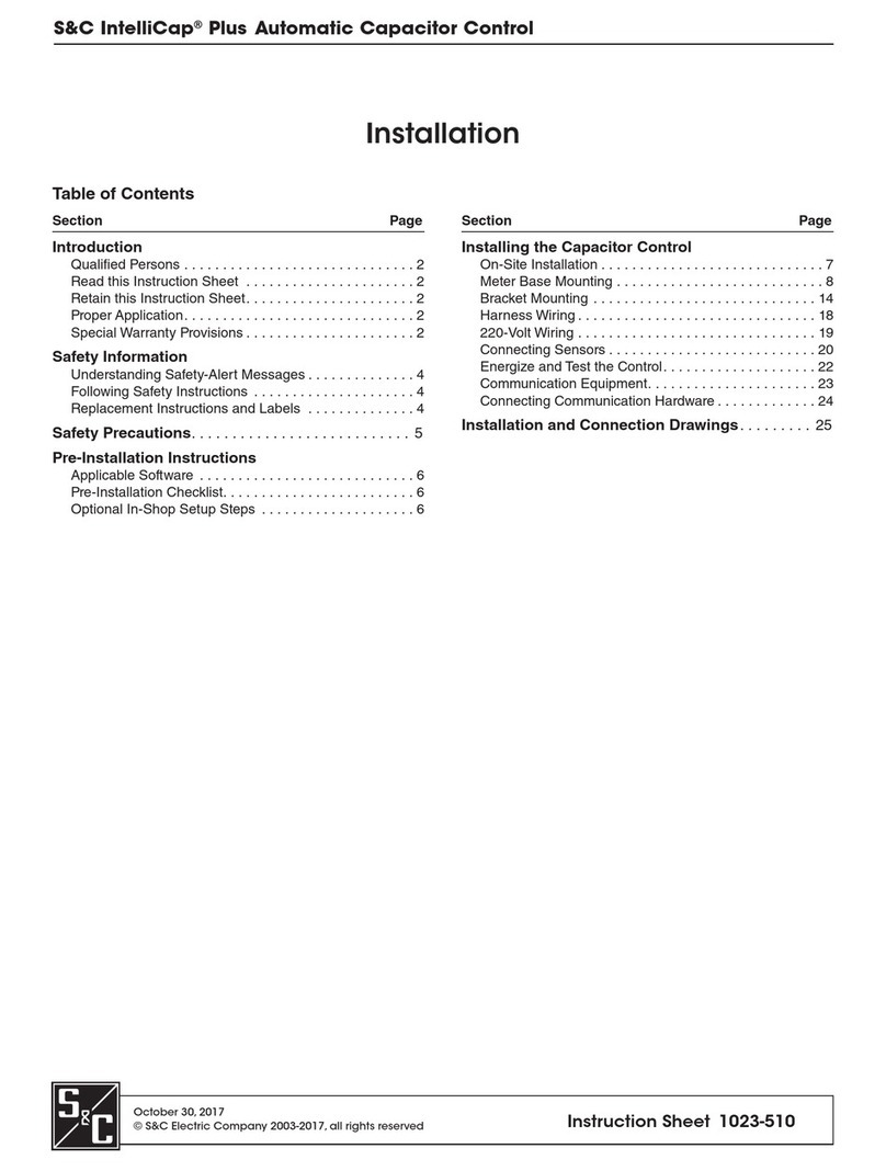
S&C BankGuard PLUS Manual

S&C ELECTRIC COMPANY
Specialists in Electric Power Switching and Protection
Instruction Sheet 1011-530
October 22, 2007 ©2007
Supersedes 1011-530 dated 2-13-06
TABLE OF CONTENTS
Section Page Section Page
INTRODUCTION
Qualified Persons . . . . . . . . . . . . . . . . . . . . . . . . . . . . . . . 2
Read this Instruction Sheet. . . . . . . . . . . . . . . . . . . . . . . 2
Retain this Instruction Sheet. . . . . . . . . . . . . . . . . . . . . . 2
Warranty . . . . . . . . . . . . . . . . . . . . . . . . . . . . . . . . . . . . . . 2
Latest Document Release . . . . . . . . . . . . . . . . . . . . . . . . 2
SAFETY INFORMATION
Understanding Safety-Alert Messages . . . . . . . . . . . . . . 3
Following Safety Instructions. . . . . . . . . . . . . . . . . . . . . 3
Replacement Instructions and Labels . . . . . . . . . . . . . . 3
UNGROUNDED WYE BANKS
Applicable Software . . . . . . . . . . . . . . . . . . . . . . . . . . . . . 5
Ungrounded Wye Banks . . . . . . . . . . . . . . . . . . . . . . . . . 5
Graphical Method . . . . . . . . . . . . . . . . . . . . . . . . . . . . . . . 5
Formula Method . . . . . . . . . . . . . . . . . . . . . . . . . . . . . . . . 9
Gross Overvoltage . . . . . . . . . . . . . . . . . . . . . . . . . . . . . 11
Unbalance Compensation . . . . . . . . . . . . . . . . . . . . . . . 12
GROUNDED WYE BANKS . . . . . . . . . . . . . . . . . . . . . . . . . . 15
Graphical Method . . . . . . . . . . . . . . . . . . . . . . . . . . . . . . 16
Formula Method . . . . . . . . . . . . . . . . . . . . . . . . . . . . . . . 19
Gross Overvoltage . . . . . . . . . . . . . . . . . . . . . . . . . . . . . 21
Alarm Level . . . . . . . . . . . . . . . . . . . . . . . . . . . . . . . . . . . 22
UNGROUNDED WYE SHUNT REACTORS
Formula Method . . . . . . . . . . . . . . . . . . . . . . . . . . . . . . . 23
Gross Overvoltage . . . . . . . . . . . . . . . . . . . . . . . . . . . . . 23
Unbalance Compensation . . . . . . . . . . . . . . . . . . . . . . . 24
USING THE LCD FOR SETUP. . . . . . . . . . . . . . . . . . . . .25
Display Mode Shortcut Buttons . . . . . . . . . . . . . . . . . .26
LCD Setup Mode . . . . . . . . . . . . . . . . . . . . . . . . . . . . . . .27
Hardware and Software Requirements . . . . . . . . . . . .29
Install IntelliLINK Software . . . . . . . . . . . . . . . . . . . . . .29
Start IntelliLINK Software . . . . . . . . . . . . . . . . . . . . . . .29
IntelliLINK Screens. . . . . . . . . . . . . . . . . . . . . . . . . . . . .31
IntelliLINK Menu Tree . . . . . . . . . . . . . . . . . . . . . . . . . .32
IntelliLINK Setup. . . . . . . . . . . . . . . . . . . . . . . . . . . . . . .32
Enter Setup Information . . . . . . . . . . . . . . . . . . . . . . . .33
Unbalance Compensation Feature . . . . . . . . . . . . . . . .40
Calculated Lockout Level. . . . . . . . . . . . . . . . . . . . . . . .47
Calculated Alarm Level . . . . . . . . . . . . . . . . . . . . . . . . .48
Normal Operation . . . . . . . . . . . . . . . . . . . . . . . . . . . . . .49
S&C BankGuard PLUS™ Control
Setup Instructions
1011-530 2
Qualified Persons
Read this
Instruction Sheet
Thoroughly and carefully read this instruction sheet before programming, operating, or
maintaining your IntelliTEAM II Interface Module. Familiarize yourself with “SAFETY
INFORMATION” on pages 3 and 4.
Retain this
Instruction Sheet
This instruction sheet is a permanent part of your IntelliTEAM II Interface Module.
Designate a location where you can easily retrieve and refer to this publication.
Warranty The standard warranty contained in S&C’s standard conditions of sale, as set forth in
Price Sheet 150, is applicable to the IntelliTEAM II Interface Module.
Latest Document
Release
The latest release of this instruction sheet is available online at www.sandc.com.
Select: Support/ Product Support Documents. Documents are posted in PDF format.
!WARNING
The equipment covered by this publication must be installed, operated, and main-
tained by qualified persons who are knowledgeable in the installation, operation, and
maintenance of overhead electric power distribution equipment along with the asso-
ciated hazards. A qualified person is one who is trained and competent in:
• The skills and techniques necessary to distinguish exposed live parts from non-live
parts of electrical equipment.
• The skills and techniques necessary to determine the proper approach distances cor-
responding to the voltages to which the qualified person will be exposed.
•The proper use of the special precautionary techniques, personal protective equip-
ment, insulating and shielding materials, and insulated tools for working on or near
exposed energized parts of electrical equipment.
These instructions are intended only for such qualified persons. They are not intended
to be a substitute for adequate training and experience in safety procedures for this type
of equipment.
INTRODUCTION

3 1011-530
Understanding
Safety-Alert
Messages
There are several types of safety-alert messages which may appear throughout this
instruction sheet as well as on labels attached to the IntelliTEAM II Interface Module.
Familiarize yourself with these types of messages and the importance of the various
signal words, as explained below.
Following Safety
Instructions
If you do not understand any portion of this instruction sheet and need assistance, con-
tact your nearest S&C Sales Office or call S&C Headquarters at (773) 338-1000, Monday
through Friday between 8:30 AM and 5:00 PM Central Standard Time. (In Canada, call
S&C Electric Canada Ltd. at (416) 249-9171.)
Replacement
Instructions and
Labels
If you need additional copies of this instruction sheet, contact your nearest S&C Sales
Office, S&C Headquarters, or S&C Electric Canada Ltd.
It is important that any missing, damaged, or faded labels on the equipment be replaced
immediately. Replacement labels are available by contacting your nearest S&C Sales
Office, S&C Headquarters, or S&C Electric Canada Ltd.
!DANGER
“DANGER” identifies the most serious and immediate hazards which will likely re-
sult in serious personal injury or death if instructions, including recommended pre-
cautions, are not followed.
!WARNING
“WARNING” identifies hazards or unsafe practices which can result in serious per-
sonal injury or death if instructions, including recommended precautions, are not fol-
lowed.
!CAUTION
“CAUTION” identifies hazards or unsafe practices which can result in minor personal
injury or product or property damage if instructions, including recommended precau-
tions, are not followed.
!NOTICE
“NOTICE” identifies important procedures or requirements that, if not followed, can
result in product or property damage if instructions are not followed.
!NOTICE
SAFETY INFORMATION
Thoroughly and carefully read this in-
struction sheet before programming
and operating your IntelliTEAM II In-
terface Module.

1011-530 4

5 1011-530
Ungrounded Wye Banks
Applicable
Software
This instruction sheet was prepared for use with software UPPD106S. You can find the
release date on the Setup disk label. For questions regarding the applicability of infor-
mation in this instruction sheet to future software releases, please contact S&C.
Ungrounded Wye
Banks
You must establish the settings for each control device installation, using either graphs
or formulas. Both methods are described in this section for ungrounded wye-con-
nected shunt capacitor banks only. It also describes how to calculate the gross over-
voltage level and when to use unbalance compensation.
Before you begin, you will need on the following information:
•The number of series groups per phase
•The number of capacitor units in parallel per series group
•The highest anticipated continuous system line-to-neutral voltage (in kV)
•The nameplate rating of the capacitor units (in kV)
This section uses the following variable names:
S=Number of series groups per phase
P=Number of capacitor units in parallel per series group
VL-n= Highest anticipated continuous system line-to-neutral voltage
Vr= Nameplate rating of the capacitor units
Vo= Voltage applied to surviving capacitor units, per unit of capacitor-unit normal volt-
age
Vn= Capacitor bank neutral-to-ground voltage, per unit of line-to-neutral voltage
F= Number of isolated capacitor units
Fc=The “critical step” – the number of isolated capacitor units at which Voexceeds the
capacitor manufacturer’s recommended maximum working voltage (which is generally
1.1 per unit)
Graphical Method Figure 1 shows the per-unit voltage applied to surviving capacitor units in a series
group (Vo), versus the percentage of capacitor units isolated from the same series
group (F/P). shows the per-unit capacitor bank neutral-to-ground voltage (Vn), versus
the percentage of capacitor units isolated from the same series group (F/P).
A. Using Figure 1, find the Vo for a series of steps corresponding to increasing values of F, up
to and including Fc.
NOTE: If the capacitor units are operating at a voltage other than the rated voltage,
multiply these F/P values by VL-n/Vr.
B. Using , find the Vn for the same series of steps corresponding to increasing values of F, up
to and including Fc.
C. Convert Vn to an actual voltage by multiplying the values found in Step B by VL-n.
D. Determine the desired lockout level: the midpoint between the Vn (actual voltage) for the
critical step Fc and the Vn (actual voltage) for Fc-1.

1011-530 6
Figure 1. Voversus F/P (Ungrounded Wye Capacitor Bank).

7 1011-530
Figure 2. Vnversus F/P (Ungrounded Wye Capacitor Bank)
Graphical Method – Example 1
An installation has the following profile:
•Highest anticipated continuous system line-to-neutral voltage (VL-n): 20 kV
•Nameplate rating of the capacitor units (Vr): 9.96 kV
•Number of series groups per phase (S): 2
•Number of capacitor units in parallel per series group (P): 10
For F= 1, enter at 10 on the horizontal scale (1/10 = 10% of capacitor units isolated
from a series group). Follow this up to the curve for S= 2 (2 series groups per phase).
Here on the vertical scale, Vo= 1.072 per unit.
Similarly, for F= 2, enter the graph at 20 on the horizontal scale (2/10 = 20% of capaci-
tor units isolated from the same series group). Follow this up to the curve for S=2.
Here, Vo= 1.16 per unit. Because we are looking for a Voof 1.1 or less per unit, our Fcin
this example is 2.
With VL-n = 20 kV and 2 series groups per phase, the capacitor units are normally oper-
ated at 10 kV. Therefore:

1011-530 8
For F= 1,
For F= 2,
For F= 1, enter at 10 on the horizontal scale. Follow this up to the curve for S= 2 (2
series groups per phase). Here, Vn= 0.018 per unit.
Similarly, for F= 2, enter the graph at 20 on the horizontal scale. Follow this up to the
curve for S=2.Here,Vn= 0.038 per unit.
To convert Vnto an actual voltage, multiply by the system voltage VL-n:
For F= 1,
For F= 2,
To determine the lockout level, calculate the midpoint value between Vnfor F= 1 and Vnfor F
= 2 (= Fc):
Thus, the desired lockout level for this capacitor bank is 560 volts.
Graphical Method – Example 2
An installation has the following profile:
•Highest anticipated continuous system line-to-neutral voltage (VL-n): 139.44 kV
•Nameplate rating of the capacitor units (Vr): 19.92 kV
•Number of series groups per phase (S): 7
•Number of capacitor units in parallel per series group (P): 12
For F= 1, enter at 8.33 on the horizontal scale (1/12 = 8.33% of capacitor units isolated
from a series group). Follow this up to a point corresponding to 7 series groups per
phase (interpolate between the curves for S= 6 and S= 8). Here on the vertical scale,
Vo= 1.085 per unit.
Similarly, for F= 2, enter the graph at 16.67 on the horizontal scale (2/12 = 16.67% of
capacitor units isolated from the same series group). Follow this up to a point corre-
sponding to 7 series groups per phase. Here, Vo= 1.18 per unit. Because we are looking
for a Voof 1.1 or less per unit, our Fcin this example is 2.
With VL-n = 139.44 kV and 7 series groups per phase, the capacitor units are normally
operated at 19.92 kV, their rated voltage. Therefore, no correction factor is needed.
For F= 1, enter at 8.33 on the horizontal scale. Follow this up to a point corresponding
Vo1.072 10kV×
9.96kV
----------------------------------1.076 per unit==
Vo1.16 10kV×
9.96kV
-------------------------------1.16 per unit==
Vn0.018 20000 volts×360 volts==
Vn0.038 20000 volts×760 volts==
360 volts 760 volts+
2
---------------------------------------------------560 volts=

9 1011-530
to 7 series groups per phase (interpolate between the curves for S= 6 and S= 8). Here,
Vn= 0.0043 per unit.
Similarly, for F= 2, enter the graph at 16.67 on the horizontal scale. Follow this up to a
point corresponding to 7 series groups per phase. Here, Vn= 0.0093 per unit.
To convert Vnto an actual voltage, multiply by the system voltage VL-n:
For F= 1,
For F= 2,
To determine the lockout level, calculate the midpoint value between Vnfor F= 1 and
Vnfor F= 2 (= Fc):
Thus, the desired lockout level for this capacitor bank is 949 volts.
Formula Method To calculate the lockout level for the capacitor bank:
A. Calculate Vofor a series of steps corresponding to increasing values of F(up to and
including Fc) using the following formulas:
B. For each value of Fused in Step A, calculate Vn:
C. Determine the desired lockout level: the midpoint between the Vn(actual voltage) for the
critical step Fcand the Vn(actual voltage) for Fc-1.
Formula Method – Example 1
An installation has the following profile:
•Highest anticipated continuous system line-to-neutral voltage (VL-n): 20 kV
•Nameplate rating of the capacitor units (Vr): 9.96 kV
•Number of series groups per phase (S): 2
•Number of capacitor units in parallel per series group (P): 10
Vn0.0043 139440 volts×600 volts==
Vn0.0093 139440 volts×1297 volts==
600 volts 1297 volts+
2
------------------------------------------------------949 volts=
Vo(volts) 3P()VLn–
2F3S()PF–()+
-------------------------------------------=
Vo(per unit) Vo(volts)
Vr
------------------------=
Vn(volts) F()VLn–
2F3S()PF–()+
-------------------------------------------=

1011-530 10
For F= 1,
For F= 2,
Because we are looking for a Voof 1.1 or less per unit, our Fcin this example is 2.
Now calculate Vn:
For F= 1,
For F= 2,
To determine the lockout level, calculate the midpoint value between Vnfor F= 1 and Vnfor F
= 2 (= Fc):
Thus, the desired lockout level for this capacitor bank is 563 volts.
Formula Method – Example 2
An installation has the following profile:
•Highest anticipated continuous system line-to-neutral voltage (VL-n): 139.44 kV
•Nameplate rating of the capacitor units (Vr): 19.92 kV
•Number of series groups per phase (S): 7
•Number of capacitor units in parallel per series group (P): 12
Vo(volts) 3 10 20000⋅⋅
21() 32⋅()10 1–()+
------------------------------------------------------- 10714 volts==
Vo(per unit) 10714
9960
---------------1.0757 per unit (or 7.57% overvoltage)==
Vo(volts) 3 10 20000⋅⋅
22() 32⋅()10 2–()+
------------------------------------------------------- 11538 volts==
Vo(per unit) 11538
9960
---------------1.1585 per unit (or 15.85% overvoltage)==
Vn(volts) 1() 20000⋅
21() 32⋅()10 1–()+
------------------------------------------------------- 357 volts==
Vn(volts) 2() 20000⋅
22() 32⋅()10 2–()+
------------------------------------------------------- 769 volts==
357 volts 769 volts+
2
---------------------------------------------------563 volts=

11 1011-530
For F= 1,
For F= 2,
Because we are looking for a Voof 1.1 or less per unit, our Fcin this example is 2.
Now calculate Vn:
For F= 1,
For F= 2,
To determine the lockout level, calculate the midpoint value between Vnfor F= 1 and Vnfor F
= 2 (= Fc):
Thus, the desired lockout level for this capacitor bank is 951 volts.
Gross
Overvoltage
You can calculate the capacitor bank neutral-to-ground voltage (Vn) resulting from a
fault within the capacitor bank that would short out an entire series group:
The desired gross overvoltage lockout level is the midpoint between the Vnfor the crit-
ical step and the Vnresulting from shorting out a series group.
For Example 1 above, the Vnfor the critical step (Fc= 2) was 769 volts. The Vnresult-
ing from shorting out a series group is:
Vo(volts) 3 12 139440⋅⋅
21() 37⋅()12 1–()+
------------------------------------------------------- 21544 volts==
Vo(per unit) 21544
19920
---------------1.0815 per unit (or 8.15% overvoltage)==
Vo(volts) 3 12 139440⋅⋅
22() 37⋅()12 2–()+
------------------------------------------------------- 23457 volts==
Vo(per unit) 23457
19920
---------------1.1776 per unit (or 17.76% overvoltage)==
Vn(volts) 1() 139440⋅
21() 37⋅()12 1–()+
------------------------------------------------------- 598 volts==
Vn(volts) 2() 139440⋅
22() 37⋅()12 2–()+
------------------------------------------------------- 1303 volts==
598 volts 1303 volts+
2
------------------------------------------------------951 volts=
Vn1
3S2–
---------------VLn–
=
Vn1
32() 2–
--------------------20000 volts 5000 volts==

1011-530 12
Therefore, the desired gross overvoltage lockout level is:
For Example 2 above, the Vnfor the critical step (Fc= 2) was 1303 volts. The Vnresult-
ing from shorting out a series group is:
Therefore, the desired gross overvoltage lockout level is:
NOTE: If the calculated gross overvoltage lockout level is more than 65,536 volts, set
the setpoint value to its maximum level.
Unbalance
Compensation
A certain amount of error voltage is always present between the capacitor bank neutral
and ground. This voltage comes from system voltage imbalances and/or inherent
capacitor bank imbalances (from manufacturing tolerance variations among capacitor
units in the bank). Because it is impossible to predict how these error voltages will
combine vectorially, it is important that the magnitude of the error voltage remain low
compared to the magnitude of the bank neutral-to-ground voltage resulting from isola-
tion of one capacitor unit.
For example, the error voltage may be additive with respect to the neutral-to-ground
voltage resulting from isolation of capacitor in one phase leg, but subtractive with
respect to the neutral-to-ground voltage resulting from isolation of capacitor units in
another leg.
In general, you should use the unbalance compensation feature if the magnitude of the
error voltage approaches 50% of the value of the neutral-to-ground voltage calculated
for one isolated capacitor unit.
If the capacitor bank manufacturer can supply an estimate of the per-unit imbalances
between phases, and if you know the per-unit system voltage imbalances between
phases, you can calculate an estimate of the error voltage:
769 volts 5000 volts+
2
------------------------------------------------------2885 volts=
Vn1
37() 2–
--------------------139440 volts 7339 volts==
1303 volts 7339 volts+
2
---------------------------------------------------------4321 volts=
Error Voltage
from Capacitor Bank
Imbalance
Per-unit
Capacitor Bank
Imbalance
⎝⎠
⎜⎟
⎜⎟
⎜⎟
⎛⎞
System
Line-to-Neutral
Voltage
⎝⎠
⎜⎟
⎜⎟
⎜⎟
⎛⎞
3
------------------------------------------------------------------------------------------------=

13 1011-530
Unbalance Compensation – Example 1
Assume a per-unit capacitor bank imbalance of 0.01 and a per-unit system voltage
imbalance of 0.005.
If these error voltages are additive, the total error voltage could be as high as
100 volts – 28% of the neutral-to-ground voltage resulting from the isolation of one
capacitor unit (357 volts in this example). Therefore, you do not need to use unbalance
compensation (and the required additional potential devices) unless field experience
indicates otherwise.
Unbalance Compensation – Example 2
Assume a per-unit capacitor bank imbalance of 0.01 and a per-unit system voltage
imbalance of 0.005.
If these error voltages are additive, the total error voltage could be as high as
697.2 volts. This does require unbalance compensation, since the neutral-to-ground
voltage resulting from the isolation of one capacitor unit in this example is 598 volts.
Error Voltage
from System Voltage
Imbalance
Per-unit
System Voltage
Imbalance
⎝⎠
⎜⎟
⎜⎟
⎜⎟
⎛⎞
System
Line-to-Neutral
Voltage
⎝⎠
⎜⎟
⎜⎟
⎜⎟
⎛⎞
3
------------------------------------------------------------------------------------------------=
Error Voltage
from Capacitor Bank
Imbalance
0.01()20000 volts()
3
-------------------------------------------------66.7 volts==
Error Voltage
from System Voltage
Imbalance
0.005()20000 volts()
3
----------------------------------------------------33.3 volts==
Error Voltage
from Capacitor Bank
Imbalance
0.01()139440 volts()
3
----------------------------------------------------464.8 volts==
Error Voltage
from System Voltage
Imbalance
0.005()139440 volts()
3
-------------------------------------------------------232.4 volts==

1011-530 14
Field Determination of the need for Unbalance Compensation.
Close the capacitor bank switching device to energize the capacitor bank.
Verify that no capacitor units have been isolated from the capacitor bank (check for
blown fuses).
The LCD should display a voltage that is essentially zero, or at most 50% of the capaci-
tor bank neutral-to-ground voltage calculated to result from the isolation of one capaci-
tor unit. If the voltage reading exceeds the 50% guideline, it will be necessary to either
increase the alarm level setting or to utilize the optional Unbalance Compensation fea-
ture.
Coordinating Bank Lockout and Individual Capacitor Unit Fuses
It is important to coordinate capacitor bank isolation and lockout with the individual
capacitor unit fuses. The control device should not lock out before the fuse of the last-
failing capacitor unit has had sufficient time to operate. If the fuse does not operate,
there will be no indication of which capacitor unit was in the process of failing.
In general, bank lockout and the individual capacitor unit fuses will be coordinated if
all of the following are true:
The lockout and alarm levels are set as described above (graphical method or formula
method.
The lockout delay time is adequate.
The individual capacitor unit fuses use a fusing ration of 1.25 or less.
The gross overvoltage circuit time delay should be a minimum of 0.5 seconds* plus the
elapsed time between energization of the capacitor bank switching device opening cir-
cuit and closing of the switching device “b” contact (which is coincident with mechani-
cal parting of the disconnect blades, if an S&C Circuit-Switcher is furnished).
For example, if the capacitor-bank switching device is a 230-kV S&C Circuit-Switcher,
the minimum gross overvoltage circuit time delay setting should be 0.5 seconds plus 0.6
seconds, or 1.1 seconds total. The elapse time between energization of the opening cir-
cuit and mechanical parting of the disconnect blades can be approximated as 40% of
the maximum operating time of the particular S&C Circuit-Switcher used.
* Required to prevent gross overvoltage lockout due to transient system voltage.

15 1011-530
You must establish the settings for each control device installation, using either graphs
or formulas. Both methods are described in this section for grounded wye-connected
shunt capacitor banks only. It also describes how to calculate the gross overvoltage
and alarm levels, and how to coordinate capacitor bank isolation with the individual
capacitor unit fuses.
Both the graphical and formula methods assume that the intermediate tap point for
each phase of the bank is located as follows:
•For capacitor banks with an even number of series groups per phase, the number
of series groups between the tap point and ground should equal the number of
series groups between the tap point and the line.
•For capacitor banks with an odd number of series groups per phase, the number
of series groups between the tap point and ground should be one less than the
number of series groups between the tap point and the line.
Before you begin, you will need on the following information:
•The number of series groups per phase
•The number of capacitor units in parallel per series group
•The highest anticipated continuous system line-to-neutral voltage (in kV)
•The nameplate rating of the capacitor units (in kV)
This section uses the following variable names:
S= Number of series groups per phase
P= Number of capacitor units in parallel per series group
VL-n = Highest anticipated continuous system line-to-neutral voltage
VL-g = Highest anticipated continuous system line-to-ground voltage
Vr= Nameplate rating of the capacitor units
Vo= Voltage applied to surviving capacitor units, per unit of capacitor-unit normal voltage
Utp = Tap-point voltage percent imbalance
F= Number of isolated capacitor units
Fc= The “critical step” – the number of isolated capacitor units at which Voexceeds the
capacitor manufacturer’s recommended maximum working voltage (which is
generally 1.1 per unit)
NOTE: The values of Utp that you find in this section (whether using the graphs or the
formulas) are valid for the isolation of capacitor units in any series group of a capacitor
bank with an even number of series groups per phase. When the total number of series
groups per phase is odd, the values of Utp are also valid for the isolation of capacitor
units in any series located between the tap point and the line.
When the total number of series groups per phase is odd, and the capacitor unit is
located between the tap point and ground, you must multiply Utp by the following
adjustment factor:
Adjustment factor S1+
S1–
------------=
Grounded Wye Banks

1011-530 16
Graphical Method Figure 3 shows the per-unit voltage applied to surviving capacitor units in a series
group (Vo), versus the percentage of capacitor units isolated from the same series
group (F/P). shows the tap-point voltage percent imbalance (Utp), versus the percent-
age of capacitor units isolated from the same series group (F/P).
A. Using , find the Vofor a series of steps corresponding to increasing values of F, up to and
including Fc.
NOTE: If the capacitor units are operating at a voltage other than the rated voltage,
multiply these F/P values by VL-n/Vr.
B. Using , find the Utp for the same series of steps corresponding to increasing values of F, up
to and including Fc.
C. Determine the desired lockout level: the midpoint between the Utp for the critical step Fc
and the Utp for Fc-1. (For capacitor banks with an odd number of series groups per phase,
compute alternate values of Utp using the adjustment factor, then choose a lockout level
that provides the best overall response.)
Figure 3. Voversus F/P (Grounded Wye Capacitor Bank).

17 1011-530
Graphical Method – Example 1
An installation has the following profile:
•Highest anticipated continuous system line-to-neutral voltage (VL-n): 20 kV
•Nameplate rating of the capacitor units (Vr): 9.96 kV
•Number of series groups per phase (S): 2
•Number of capacitor units in parallel per series group (P): 10
For F= 1, enter at 10 on the horizontal scale (1/10 = 10% of capacitor units isolated
from a series group). Follow this up to the curve for S= 2 (2 series groups per phase).
Here on the vertical scale, Vo= 1.053 per unit.
Similarly, for F= 2, enter the graph at 20 on the horizontal scale (2/10 = 20% of capaci-
tor units isolated from the same series group). Follow this up to the curve for S=2.
Here, Vo= 1.11 per unit. Because we are looking for a Voof 1.1 or less per unit, our Fcin
this example is 2.
Figure 4. Utp versus F/P (Grounded Wye Capacitor Bank).
With VL-n = 20 kV and 2 series groups per phase, the capacitor units are normally oper-
ated at 10 kV. Therefore:
For F= 1,
For F= 2,
Vo1.053 10kV×
9.96kV
----------------------------------1.057 per unit==

1011-530 18
For F= 1, enter at 10 on the horizontal scale. Follow this up to the curve for S= 2 (2
series groups per phase). Here, Utp = 5.2%.
Similarly, for F= 2, enter the graph at 20 on the horizontal scale. Follow this up to the
curve for S=2.Here,Utp = 11%.
To determine the lockout level, calculate the midpoint value between Utp for F= 1 and
Utp for F= 2 (= Fc):
Thus, the desired lockout level for this capacitor bank is 8.1%.
Graphical Method – Example 2
An installation has the following profile:
•Highest anticipated continuous system line-to-neutral voltage (VL-n): 139.44 kV
•Nameplate rating of the capacitor units (Vr): 19.92 kV
•Number of series groups per phase (S): 7
•Number of capacitor units in parallel per series group (P): 12
For F= 1, enter at 8.33 on the horizontal scale (1/12 = 8.33% of capacitor units isolated
from a series group). Follow this up to a point corresponding to 7 series groups per
phase (interpolate between the curves for S= 6 and S= 8). Here on the vertical scale,
Vo= 1.076 per unit.
Similarly, for F= 2, enter the graph at 16.67 on the horizontal scale (2/12 = 16.67% of
capacitor units isolated from the same series group). Follow this up to a point corre-
sponding to 7 series groups per phase. Here, Vo= 1.17 per unit. Because we are looking
for a Voof 1.1 or less per unit, our Fcin this example is 2.
With VL-n = 139.44 kV and 7 series groups per phase, the capacitor units are normally
operated at 19.92 kV, their rated voltage. Therefore, no correction factor is needed.
For F= 1, enter at 8.33 on the horizontal scale. Follow this up to a point corresponding
to 7 series groups per phase (interpolate between the curves for S= 6 and S= 8). Here,
Utp = 1.3%.
Similarly, for F= 2, enter the graph at 16.67 on the horizontal scale. Follow this up to a
point corresponding to 7 series groups per phase. Here, Utp = 2.8%.
Because the number of series groups per phase in this example is odd, you must com-
pute alternate values of Utp using the adjustment factor for isolation of capacitor units
in a series group between the tap point and ground. In this example, the adjustment
factor is (7 + 1)/(7 - 1) = 1.33.
For F= 1,
For F= 2,
In this example, the desired tap-point voltage imbalance lockout level is the midpoint
Vo1.11 10kV×
9.96kV
-------------------------------1.114 per unit==
5.2% 11%+
2
------------------------------ 8.1%=
Utp 1.3% 1.33×1.7%==
Utp 2.8% 1.33×3.7%==

19 1011-530
between the higher value of Utp for F= 1 and the lower value of Utp for F= 2 (= Fc):
Thus, the desired lockout level for this capacitor bank is 2.25%.
Formula Method To calculate the lockout level for the capacitor bank:
A. Calculate Vofor a series of steps corresponding to increasing values of F(up to and
including Fc) using the following formulas:
B. For each value of Fused in Step A, calculate Utp:
C. Determine the desired lockout level: the midpoint between the Utp for the critical step Fc
and the Utp for Fc-1. (For capacitor banks with an odd number of series groups per phase,
compute alternate values of Utp using the adjustment factor, then choose a lockout level
that provides the best overall response.)
Formula Method – Example 1
An installation has the following profile:
•Highest anticipated continuous system line-to-ground voltage (VL-g): 20 kV
•Nameplate rating of the capacitor units (Vr): 9.96 kV
•Number of series groups per phase (S): 2
•Number of capacitor units in parallel per series group (P): 10
For F= 1,
For F= 2,
1.7% 2.8%+
2
--------------------------------2.25%=
Vo(volts) PV
Lg–
()
SP F–()F+
-------------------------------=
Vo(per unit) Vo(volts)
Vr
------------------------=
Utp (volts) 100F
SP F–()F+
-------------------------------=
Vo(volts) 10 20000⋅
210 1–()1+
-------------------------------- 10526 volts==
Vo(per unit) 10526
9960
---------------1.0568 per unit (or 5.68% overvoltage)==

1011-530 20
Because we are looking for a Voof 1.1 or less per unit, our Fcin this example is 2.
Now calculate Utp:
For F= 1,
For F= 2,
To determine the lockout level, calculate the midpoint value between Utp for F= 1 and
Utp for F= 2 (= Fc):
Thus, the desired lockout level for this capacitor bank is 8.19%.
Formula Method – Example 2
An installation has the following profile:
•Highest anticipated continuous system line-to-ground voltage (VL-g): 139.44 kV
•Nameplate rating of the capacitor units (Vr): 19.92 kV
•Number of series groups per phase (S): 7
•Number of capacitor units in parallel per series group (P): 12
For F= 1,
For F= 2,
Because we are looking for a Voof 1.1 or less per unit, our Fcin this example is 2.
Now calculate Utp:
Vo(volts) 10 20000⋅
210 2–()2+
-------------------------------- 11111 volts==
Vo(per unit) 11111
9960
---------------1.1156 per unit (or 11.56% overvoltage)==
Utp 100 1⋅
210 1–()1+
-------------------------------- 5.26%==
Utp 100 2⋅
210 2–()2+
-------------------------------- 11.11%==
5.26% 11.11%+
2
-----------------------------------------8.19%=
Vo(volts) 12 139440⋅
712 1–()1+
-------------------------------- 21452 volts==
Vo(per unit) 21452
19920
---------------1.0769 per unit (or 7.69% overvoltage)==
Vo(volts) 12 139440⋅
712 2–()2+
-------------------------------- 23240 volts==
Vo(per unit) 23240
19920
---------------1.1667 per unit (or 16.67% overvoltage)==
Other manuals for BankGuard PLUS
4
Table of contents
Other S&C Controllers manuals

S&C
S&C TripSaver II User manual

S&C
S&C Vista SD Owner's manual

S&C
S&C BankGuard PLUS Instruction Manual

S&C
S&C GridMaster User manual

S&C
S&C IntelliCap User manual

S&C
S&C BankGuard PLUS Guide

S&C
S&C PMH Installation instructions

S&C
S&C Micro-AT User manual

S&C
S&C BankGuard PLUS User manual

S&C
S&C IntelliCap Instruction Manual

S&C
S&C IntelliCap Plus Operating instructions

S&C
S&C Vista Owner's manual

S&C
S&C 6800 Series User manual

S&C
S&C PMH Operation and maintenance manual

S&C
S&C Micro-AT User manual

S&C
S&C Micro-AT User manual

S&C
S&C IntelliCap 2000 User manual

S&C
S&C 6802 User guide

S&C
S&C 6800 Series Parts list manual

S&C
S&C Vista SD Owner's manual