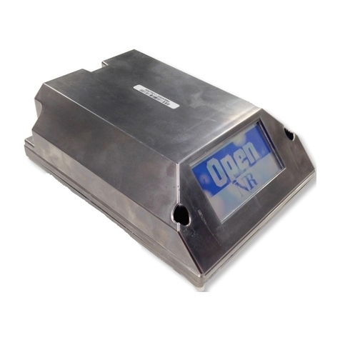
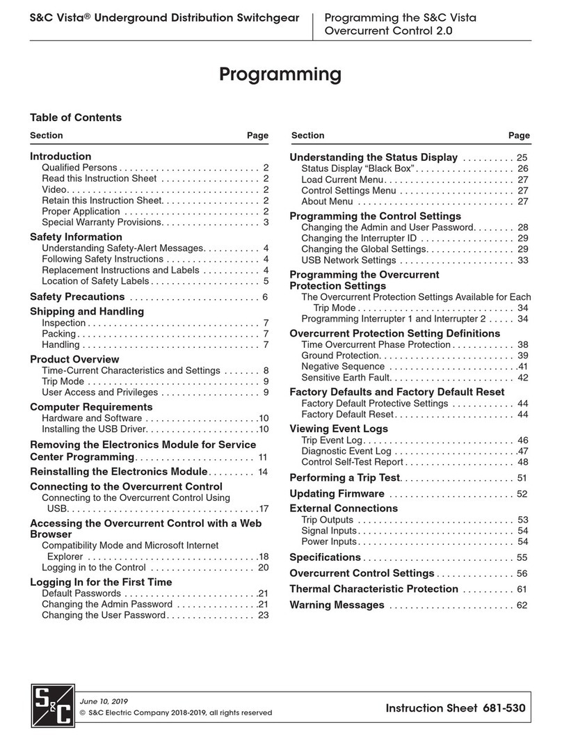
S&C Vista SD Owner's manual

S&C Vista®SD Underground
Distribution Switchgear
Programming the S&C Vista Overcurrent Control 2.0
June 10, 2019
© S&C Electric Company 2018-2019, all rights reserved Instruction Sheet 695-535
Programming
Table of Contents
Section Page Section Page
Introduction
Qualified Persons ........................... 2
Read this Instruction Sheet ................... 2
Video..................................... 2
Retain this Instruction Sheet. . . . . . . . . . . . . . . . . . . 2
Proper Application .......................... 2
Special Warranty Provisions................... 3
Safety Information
Understanding Safety-Alert Messages........... 4
Following Safety Instructions .................. 4
Replacement Instructions and Labels ........... 4
Location of Safety Labels ..................... 5
Safety Precautions ........................6
Shipping and Handling
Inspection ................................. 7
Packing ................................... 7
Handling .................................. 7
Product Overview
Power and Sensing.............................8
Time-Current Characteristics and Settings ...........8
Trip Mode ....................................9
User Access and Privileges ......................9
Computer Requirements
Hardware and Software ......................10
Installing the USB Driver. . . . . . . . . . . . . . . . . . . . . .10
Connecting to the Overcurrent Control
Using USB ...............................11
Accessing the Overcurrent Control with a
Web Browser
Compatibility Mode and Microsoft Internet Explorer ...12
Logging Into the Control ........................14
Logging In for the First Time
Default Passwords ............................15
Changing the Admin Password ...................15
Changing the User Password ....................17
Understanding the Status Display ........... 19
Status Display “Black Box” ................... 20
Load Current Menu..........................21
Control Settings Menu .......................21
About Menu ...............................21
Programming the Control Settings
Changing the Admin and User Password........ 22
Changing the Interrupter ID .................. 23
Changing the Global Settings................. 23
USB Network Settings ...................... 27
Programming the Overcurrent
Protection Settings
Programming Interrupter 1 and Interrupter 2 ..... 28
Overcurrent Protection Setting Definitions
Time Overcurrent Phase Protection .............31
Ground Protection.......................... 32
Negative Sequence ........................ 33
Sensitive Earth Fault........................ 34
Factory Defaults and Factory Default Reset
Factory Default Protective Settings ............ 36
Factory Default Reset ....................... 37
Viewing Event Logs
Trip Event Log................................39
Diagnostic Event Log ..........................40
Control Self-Test Report ........................41
Performing a Trip Test...................... 43
Updating Firmware ........................44
External Connections
Trip Outputs .............................. 45
Signal Inputs .............................. 46
Power Inputs .............................. 46
Specifications............................ 47
Overcurrent Control Settings ..............48
Thermal Characteristic Protection ..........53
Warning Messages .......................54
2S&C Instruction Sheet 695-535
Introduction
Qualified Persons WARNING
The equipment covered by this publication must be installed, operated, and
maintained by qualified persons who are knowledgeable in the installation, operation,
andmaintenanceofundergroundelectricpowerdistributionequipment,vault-mounted
switchgear, and switchgear installed in metal enclosures, along with all associated
hazards. A qualified person is someone who is trained and competent in:
• The skills and techniques necessary to distinguish exposed live parts from nonlive
parts of electrical equipment.
• The skills and techniques necessary to determine the proper approach distances
corresponding to the voltages to which the qualified person will be exposed.
• The proper use of special precautionary techniques, personal protective
equipment, insulated and shielding materials, and insulated tools for working on
or near exposed energized parts of electrical equipment.
• The principles of selective coordination and system protection.
These instructions are intended ONLY for such qualified persons. They are
not intended to be a substitute for adequate training and experience in safety
procedures for this type of equipment.
Read this
Instruction Sheet NOTICE
Thoroughly and carefully read this instruction sheet and all materials included in the
product’s S&C Instruction Handbook before installing or operating your S&C Vista
Overcurrent Control. Familiarize yourself with the Safety Information on pages 4
and 5 and the Safety Precautions on page 6.
Video A video of this instruction sheet is available at www.sandc.com/videos/install-occ.
The video is supplementary to this instruction sheet and should in no way be considered
a replacement for the written instructions.
Retain this
Instruction Sheet
This instruction sheet is a permanent part of your S&C Vista SD Underground Distribution
Switchgear. Designate a location where you can easily retrieve and refer to this publication.
A copy of these instructions should be stored in the instruction manual holder, if present.
The latest version is available online in PDF format at sandc.com/en/Support/
Product-Literature.
Proper Application WARNING
The equipment in this publication is only intended for use with S&C Vista SD
Underground Distribution Switchgear. The switchgear must be installed according to
its applicable instruction sheet. The application must be within the ratings furnished
for the equipment. Ratings for the Vista SD Underground Distribution Switchgear
are listed on the ratings table in Specification Bulletin 695-31. The ratings are also
on the S&C nameplate affixed to the product.

S&C Instruction Sheet 695-535 3
Introduction
Special Warranty
Provisions
The standard warranty contained in seller’s standard conditions of sale, as set forth in
Price Sheets 150 and 181, applies to Vista SD Underground Distribution Switchgear and
its associated options. The Vista Overcurrent Control 2.0. has the following warranty: the
rst and second paragraphs of Price Sheet 150 warranty are replaced with the following:
(1) General: The seller warrants to the immediate purchaser or end user for a period
of 10 years from the date of shipment that the equipment delivered will be of the
kind and quality specified in the contract description and will be free of defects of
workmanship and material. Should any failure to conform to this warranty appear
under proper and normal use within 10 years after the date of shipment the seller
agrees, upon prompt notification thereof and confirmation that the equipment has
been stored, installed, operated, and maintained in accordance with recommenda-
tions of the seller and standard industry practice, to correct the nonconformity
either by repairing any damaged or defective parts of the equipment or (at seller’s
option) by shipment of necessary replacement parts. The seller’s warranty does not
apply to any equipment that has been disassembled, repaired, or altered by anyone
other than the seller. This limited warranty is granted only to the immediate pur-
chaser or, if the equipment is purchased by a third party for installation in third
party equipment, the end user of the equipment. The seller’s duty to perform under
any warranty may be delayed, at the seller’s sole option, until the seller has been
paid in full for all goods purchased by the immediate purchaser. No such delay shall
extend the warranty period.
The seller further warrants to the immediate purchaser or end user that for a
period of two years from the date of shipment the software will perform substan-
tially in accordance with the then-current release of specifications if properly used
in accordance with the procedures described in seller’s instructions. The seller’s
liability regarding any of the software is expressly limited to exercising its reason-
able efforts in supplying or replacing any media found to be physically defective or
in correcting defects in the software during the warranty period. The seller does
not warrant the use of the software will be uninterrupted or error-free.

4S&C Instruction Sheet 695-535
Safety Information
Understanding
Safety-Alert
Messages
Several types of safety-alert messages may appear throughout this instruction sheet and
on labels attached to the S&C Vista Overcurrent Control. Familiarize yourself with these
types of messages and the importance of these various signal words:
DANGER
“DANGER” identifies the most serious and immediate hazards that will likely
result in serious personal injury or death if instructions, including recommended
precautions, are not followed.
WARNING
“WARNING” identifies hazards or unsafe practices that can result in serious
personal injury or death if instructions, including recommended precautions, are
not followed.
CAUTION
“CAUTION” identifies hazards or unsafe practices that can result in minor
personal injury if instructions, including recommended precautions, are not followed.
NOTICE
“NOTICE” identifies important procedures or requirements that can result in
product or property damage if instructions are not followed.
Following Safety
Instructions
If you do not understand any portion of this instruction sheet and need assistance, contact
your nearest S&C Sales Ofce or S&C Authorized Distributor. Their telephone numbers
are listed on S&C’s website sandc.com or call the S&C Global Monitoring and Support
Center at 1-888-762-1100 or 1-773-338-1000 outside the U.S.
NOTICE
Read this instruction sheet thoroughly and carefully
before installing and programming your S&C Vista
Overcurrent Control.
Replacement
Instructions
and Labels
If additional copies of this instruction sheet are needed, contact your nearest S&C Sales
Ofce, S&C Authorized Distributor, S&C Headquarters, or S&C Electric Canada Ltd.
It is important that any missing, damaged, or faded labels on the equipment be replaced
immediately. Replacement labels are available by contacting your nearest S&C Sales
Ofce, S&C Authorized Distributor, S&C Headquarters, or S&C Electric Canada Ltd.

S&C Instruction Sheet 695-535 5
Safety Information
Reorder Information for Safety Labels
Location Safety Alert Message Description Part Number
ADANGER Hazardous voltage inside. Will shock, burn, or cause death . . . G-9636
BDANGER Never disconnect CT secondary circuits without de-energizing the switchgear.
Hazardous voltage will shock, burn, or cause death . . . G-9635
CNOTICE To remove or install the control, grasp both the control handle and the tab
opposite the handle . . . G-9688
Location of Safety Labels
B
C
A

6S&C Instruction Sheet 695-535
Safety Precautions
DANGER
The Vista SD Underground Distribution System protected by this overcurrent
control operates at high voltage. Failure to observe the precautions below will
result in serious personal injury or death.
Some of these precautions may differ from your company’s operating procedures
and rules. Where a discrepancy exists, follow your company’s operating procedures
and rules.
1. QUALIFIED PERSONS. Access to the Vista
Overcurrent Control must be restricted only to
qualified persons.
2. SAFETY PROCEDURES. Always follow safe
operating procedures and rules. Always maintain
proper clearance from energized components.
3. PERSONAL PROTECTIVE EQUIPMENT. Always
use suitable protective equipment, such as rubber
gloves, rubber mats, hard hats, safety glasses, and
arc-flash clothing in accordance with safe operating
procedures and rules.
4. SAFETY LABELS. Do not remove or obscure any of
the “DANGER,” “WARNING,” “CAUTION,” or
“NOTICE” labels and tags. Remove tags ONLY if
instructed to do so.
5. ENERGIZED COMPONENTS. Always consider all
parts live until de-energized, tested, and grounded.
6. MAINTAINING PROPER CLEARANCE. Always
maintain proper clearance from energized
components.

S&C Instruction Sheet 695-535 7
Shipping and Handling
Examine the shipment for external evidence of damage as soon after receipt as possible,
preferable before the carrier departs. Check the bill of lading to make sure the listed
shipping packages are present.
If there is visible loss and/or damage:
1. Notify the delivering carrier immediately.
2. Ask for a carrier inspection.
3. Note condition of shipment on all copies of the delivery receipt.
4. File a claim with the carrier.
If concealed damaged is discovered:
1. Notify the delivering carrier within 15 days of receipt of shipment.
2. Ask for a carrier inspection.
3. File a claim with the carrier.
Notify S&C Electric Company in all instances of loss and/or damage.
The overcurrent control for the S&C Vista SD Underground Distribution System is
housed in a enclosure mounted on the operation side of the switchgear. The enclosure
is fully submersible.
DANGER
Never disconnect the current transformer secondary circuits without de-energizing
the switchgear. Hazardous voltage is present and will shock, burn, or cause death.
NOTICE
S&C does not recommend removing the submersible S&C Overcurrent
Control used in Vista SD Underground Distribution Switchgear from its enclosure
for workbench programming. Opening the submersible enclosure may damage the
sealing gasket. Contact your local S&C Sales Office or the S&C Global Support
and Monitoring Center at 1-888-762-1100 (or 1-773-338-1000 outside the U.S.) for
more information.
Inspection
Packaging
Handling

8S&C Instruction Sheet 695-535
Product Overview
The overcurrent control is programmed using a personal computer connected to the
control via a USB cable. The control features a variety of time-current characteristic
(TCC) curves and denite time settings listed in the "Overcurrent Control Settings" section
starting on page 47. Each overcurrent control can control up to two fault interrupters.
Current transformers are integral to the switchgear. These current transformers pro-
vide primary current sensing for the switchgear. The overcurrent control is capable of
sensing and responding to phase overcurrents, ground overcurrents, negative sequence,
and sensitive earth faults.
The power derived from the current transformers is used to operate the control and
to charge the trip capacitors that discharge into magnetic latching solenoids to trip
the fault interrupters during a fault. No external power is required for operation of the
control in the field.
In the absence of power from the current transformers, the overcurrent control will
draw its power from the connected personal computer via the USB connection.
The overcurrent control features time-current characteristic (TCC) curves consisting
of phase-overcurrent curves and ground-overcurrent curves. The families of curves are
as follows:
• IEEE (ANSI. U.S.) curves per IEEE Standard C37.112-1996 and IEC curves per IEC
60255-3: U1, U2, U3, U4, U5, C1, C2, C3, C4, and C5.
• S&C standard speed curves (for use in place of conventional “E”-rated power fuses)
• S&C “K”-speed curves (for use in place of conventional “K”-rated power fuses)
• S&C “T”-speed curves (for use in place of conventional “T”-rated power fuses)
• Tap fault interrupter curves
• Main fault interrupter curves
The TCC curves can be customized into hundreds of different curves using a variety of
definite-time delay settings. For even more specialized shapes, there are two definite-time
settings that can be programmed. The definite-time settings can be programmed with
a minimum time value of 0 seconds, which is used to create an instantaneous overcur-
rent response. Ground Protection, Negative Sequence, and Sensitive Earth Fault
protection elements are also available. The factory default settings for the overcurrent
control are shown in the “Factory Default Protective Settings” section on page 35.
A choice of 50- or 60-Hertz operation is also offered.
Power and Sensing
Time-Current
Characteristics and
Settings

S&C Instruction Sheet 695-535 9
Product Overview
Three-phase fault interrupters are designed for three-phase tripping. Single-phase
tripping is not possible with three-phase fault interrupters.
The overcurrent control has three levels of access. All access levels can view the
status page, which includes the status of the control, load currents, settings, and
firmware version.
Table 1. Access Levels
Access Level Description
admin Can access the Time Overcurrent Phase Protection menus of “Interrupter 1” and
“Interrupter 2” and make settings changes.
Can access all Control Settings and make changes.
Can change admin password and user password.
Can clear Diagnostic and Trip Event Logs.
Can perform a trip test.
Can upgrade firmware.
Can perform a factory default reset.
user Can access the protective settings menus of “Interrupter 1” and “Interrupter 2” and
make changes.
Can change user password ONLY.
Can clear Diagnostic and Trip Event Logs.
View button Can view and clear Diagnostic and Trip Event Logs.
Trip Mode
User Access and
Privileges

10 S&C Instruction Sheet 695-535
Computer Requirements
To access the Overcurrent Control you will need:
• USB driver from www.sandc.com/vistaocc
• Administrative privileges to install software on your personal computer for USB
driver installation
• A computer with a USB 2.0 (or newer) Type A USB receptacle
• A computer running Microsoft Windows (7 through Windows 10), with Microsoft
Internet Explorer 8.0 or later or Mozilla Firefox 34.0.5 or later recommended (Google
Chrome and Microsoft Edge can be used. Contact S&C Technical Support for a list of
known issues using non-recommended browsers.)
• A USB 2.0 Type A-to-Type A cable (A two-meter long cable is available from S&C Electric
Company, part number TR-11887.)
A Vista Overcurrent Control USB driver is required to access and program the control via
USB. The latest Vista overcurrent control USB driver software release for your version
of Microsoft Windows is posted at http://www.sandc.com/vistaocc.
NOTICE
DO NOT connect to the Vista Overcurrent Control 2.0 before installing the USB
driver available from S&C Electric Company. Connecting to the device before
installing the proper driver may prompt Microsoft Windows to install the incorrect
driver.
To install the driver:
STEP 1. There are two versions of the driver—one for Microsoft Windows 10, and one
for earlier versions of Microsoft Windows. Download the driver le for your
version of Microsoft Windows and move it from the Downloads folder to your
desktop. Double-click and follow the prompts to unzip the le.
STEP 2. After downloading the driver, disconnect from all network and Internet
connections by disabling Wi-Fi and Ethernet. As an administrator, open a
command prompt to the folder where the driver is located. To open a command
prompt:
(a) Open the Start menu in windows.
(b) In the “Search Programs and Files” box, type “cmd.exe.”
(c) Right click on cmd.exe, and select “Run as Administrator.” Type in your
admin credentials if prompted.
(d) Using the command prompt “cd” for change directory, navigate to the
directory where the USB driver les are located. In this example, the folder
is located on the desktop. The command prompt “cd” is used to change the
directory.
For example, your directory might be cd\users\<your username>\desktop\scelec-
tric-20140311. See Figure 1.
NOTICE
Your version of the driver may have a different folder name than the one shown in
Figure 1.
(e) Run “setup.bat” from the command prompt, and follow the driver-
installation dialogs to complete the installation.
Figure 1. Run “setup.bat” from the Command Prompt.
Hardware and
Software
Installing the USB
Driver

S&C Instruction Sheet 695-535 11
To connect to the overcurrent control:
STEP 1. Make sure the USB driver has been installed on the computer per the
instructions in the “Installing the USB Driver” section on page 10.
STEP 2. Remove the USB data port cap. Plug the A-male end of a USB cable, no longer
than three meters, into the USB receptacle on the side of the overcurrent
control. See Figure 2. This cable should have a minimum conductor size of
24AWG. Plug the opposite end of the USB cable into an open USB receptacle on
the PC. Windows OS will detect the overcurrent control as a USB device.
STEP 3. When nished programming the overcurrent control, make sure to replace the
data port cap.
NOTICE
Make sure the data port cover is secure after programming the control. Failure to
secure the data port cap may result in damage to the data port. A control with a
damaged data port cannot be accessed via personal computer through the port.
Connecting to the
Overcurrent Control
Using USB
Connecting to the Overcurrent Control
Figure 2. Remove the data port cap and plug a USB cable into the control. Plug the opposite
end of the cable into a PC.
USB cable
Cap

12 S&C Instruction Sheet 695-535
Accessing the Overcurrent Control with a Web Browser
The software for the overcurrent control is resident on the control and can be accessed
using a Web browser. (See the “Computer Requirements” section on page 10 for compatible
Web browsers and operating systems.) After connecting to the control by connecting to
the USB port, access the control by opening the Web browser.
Microsoft Internet Explorer may perform better when running in Compatibility mode.
If encountering unexpected behavior with Internet Explorer versions 8 through 11, please
change to Compatibility mode or contact S&C Technical Support.
STEP 1. Click on the Gear icon. (Or the Tools menu in Microsoft 8 through 10.) From the
drop down menu, click on the Compatibility View settings item. See Figure 3.
Compatibility Mode
and Microsoft Internet
Explorer
Figure 3. Choose “Compatibility View settings” from the Gear menu. (Microsoft Explorer
11 shown.)

S&C Instruction Sheet 695-535 13
STEP 2. From the Compatibility View Settings menu, uncheck the box next to “Display
Intranet sites in Compatibility View.” See Figure 4.
Accessing the Overcurrent Control with a Web Browser
Figure 4. Uncheck “Display intranet sites in Compatibility View” from the Compatibility View
Settings menu. (Microsoft Explorer 11 shown.)

14 S&C Instruction Sheet 695-535
To get to the Login screen, open a compatible Web browser and enter the address:
http://sandcvista. If an error is encountered, enter the IP address http://10.1.11.58.
This will open the Login screen. See Figure 5.
There are three types of login:
Figure 5. The Vista Overcurrent Control Login screen.
• admin – The admin login should ONLY be used when initially setting up the control
or as directed by S&C, such as for installing a rmware update.
• user – The user login should be used for general access to the control when changes
to the protective settings must be made.
• View– The View mode should be the primary means of accessing the control. The
View button allows the user to view the status of the control, load currents, protective
settings, rmware revision, and to view and clear event logs. No changes to the protec-
tive settings or control settings can be made.
For more information on the types of login privileges, see the “User Access and
Privileges” section on page 9.
To log in to the control using the admin or user login, enter the appropriate login name
and password in the Username and Password fields. Then click on the Login button.
To log in to the control using the View mode, click on the View button.
See the “Logging in for the First Time” section on page 15 for more information on
setting the admin and user passwords.
Logging Into the
Control
Accessing the Overcurrent Control with a Web Browser

S&C Instruction Sheet 695-535 15
NOTICE
DO NOT lose the admin password. For security reasons, there is no password-
retrieval system built in to the overcurrent control. If the admin password is lost, the
control must be returned to S&C Electric Company to restore access to the control.
The overcurrent control comes with two default passwords, one for the “admin” login
and one for the “user” login. (See “User access and privileges” on page 9 for details on
the access levels of the two logins.) S&C strongly recommends changing admin and user
login passwords from the default setting when rst logging in to the control. You will be
prompted to change the user login password upon the rst login under this username.
The default passwords are:
Username Password
admin 4731
user 6601
NOTICE
After changing the password, S&C recommends logging in to the “admin” login
ONLY when directed to do so by S&C Electric Company. Use the “user” login when
general changes need to be made to the Overcurrent Control settings. Use the
View button for regular access to the overcurrent control.
To change the admin password:
STEP 1. At the login screen, enter in the default admin username and password.
See Figure 6.
Default Passwords
Changing the Admin
Password
Logging In for the First Time
Figure 6. Enter the default admin username and password.

16 S&C Instruction Sheet 695-535
STEP 2. Click on the “Control Settings” tab on the side menu. Then navigate to the
“Change Admin Password” section of the Control Settings tab. See Figure 7.
Control Settings
Figure 7. The “Change Admin Password” menu.
STEP 3. If desired, click on the Eye icon on the right side of the Current Password
eld to reveal the text of the password. See Figure 8.
Eye icon
Figure 8. Click on the “Eye” icon to reveal the password.
STEP 4. Enter a new password, an alpha-numeric sequence of a minimum of 4
characters and a maximum of 12 characters with at least one letter, one number
and one special character: !, #, $, *, _ or – into the New Password eld.
Passwords are case sensitive. Re-enter the new password in the Conrm
Password eld.
STEP 5. Click on the Save button directly under the “Change Admin Password”
section. A message that the password has been saved successfully will open.
See Figure 9.
Figure 9. Click on the “Save” button. A confirmation message will display.
Logging In for the First Time

S&C Instruction Sheet 695-535 17
To change the User password:
STEP 1. At the Login screen, enter the user username and password. See Figure 10.
Figure 10. Enter the username and password.
When logging in with the user login for the rst time, prompt to change password will
open in the Control Settings menu.
STEP 2. Enter the default user password “6601.” See Figure 11.
Figure 11. The “Change User Password” menu.
Changing the User
Password
Logging In for the First Time

18 S&C Instruction Sheet 695-535
STEP 3. If desired, click on the Eye icon to on the right side of the Current Password
eld to reveal the text of the password. See Figure 12.
Figure 12. Click on the “Eye” icon to reveal the password.
STEP 4. Enter a new password, an alpha-numeric sequence of a minimum of 4
characters and a maximum of 12 characters with at least 1 letter, 1 number and
1 special character: !, #, $, *, _ or – into the New Password eld. Passwords are
case sensitive. Re-enter the new password in the Conrm Password eld.
STEP 5. Click on the Save button. A message that the password has been saved
successfully will open. See Figure 13.
Figure 13. Click on the Save button. A confirmation message will display.
NOTICE
The overcurrent control will logout the user after five minutes of inactivity. Any
settings not saved before the inactivity logout will be lost.
Logging In for the First Time
Eye icon

S&C Instruction Sheet 695-535 19
Understanding the Status Display
The Status screen and menus provide a summary of the status of the overcurrent control,
measurement of the load current of the associated fault interrupters, and the control
settings. It also provides a summary of the login status, the overcurrent control serial
number and MAC address, and the rmware installed on the control. This page can be
viewed from admin and user logins and when using the View button.
The overcurrent control has a physical LED status display located on the outside of
the electronics module that is visible when the overcurrent control is removed from its
enclosure. An on-screen replica of this status display can be viewed when a computer is
connected to the control. See Figure 14. See Table 2 for the LED key.
Figure 14. The Status screen.
Table 2. Status Display LED Key
LED Key Description
Orange Trip operation recorded
Red Element initiated trip
Green Flashing: Control OK
Solid: Control Error
White All prior trip operations cleared

20 S&C Instruction Sheet 695-535
Understanding the Status Display
The FAULT INTERRUPTER 1 and FAULT INTERRUPTER 2 orange LED displays will
indicate whether a fault interrupter has experienced a Trip event initiated by the
overcurrent control. If more than one fault interrupter has responded to a fault, both
LED displays will light. See Figure 14 on page 19.
During a Trip event, the FAULT INTERRUPTER LED will blink after passing the mini-
mum pickup level. If the current goes below the fault level and the control resets without
initiating a trip operation, the FAULT INTERRUPTER LED will turn white again. If the
fault interrupter trips, the LED will glow solid orange. The appropriate events (pickup,
timing, trip, or reset) are logged in the event log.
The CONTROL ENABLED indicator LED will flash green when the overcurrent control
is powered. When the control is operating normally, the indicator will blink. If the control
is in an error state, or a firmware update is being performed, the CONTROL ENABLED
indicator LED will glow a solid green. If the control is displaying solid green when the
firmware is NOT being updated, contact your local S&C Sales Office or the S&C Global
Support and Monitoring Center at 1-888-762-1100 (or 1-773-338-1000 outside the U.S.)
for support.
The OVERCURRENT CONDITION “A, B, and C” indicator LEDs show the phase involved
with a Phase Overcurrent Trip event, if one has occurred. If more than one phase is
involved in a Trip event, then more than one lamp may be lit. The Q and G indicators
will show whether there was a control-initiated Trip event in response to a Negative-
Sequence “Q” or Ground “G” protective setting. If more than one fault interrupter has
responded to a fault, then more than one lamp will be lit. See Table 3 for a key to the
overcurrent conditions:
Table 3. Overcurrent Conditions
Key Description
AA Phase fault
BB Phase fault
CC Phase fault
QNegative-Sequence trip
GGround
The RESET/LAMP TEST button is used on both the status screen replica and on the
physical control to test the physical LED lights and to clear the fault indication LED lights.
To test the LED lights:
Click on and hold the RST (Reset/Lamp Test) button on screen; or press and hold
the RST RESET/LAMP TEST button on the physical control. All LEDs will light, and the
Control Status display will show the present status of the control.
To clear the OVERCURRENT CONDITION indicators after an Overcurrent event:
Click on and hold the RST button on the screen or press and hold the RESET/LAMP
TEST button on the control until all LEDs (except for the OCC ENABLED LED, which
will remain blinking) show a solid color.
Status Display “Black
Box”
Other manuals for Vista SD
4
Table of contents
Other S&C Controllers manuals

S&C
S&C BankGuard PLUS Manual

S&C
S&C 6800 Series User manual

S&C
S&C BankGuard PLUS Instruction Manual

S&C
S&C IntelliCap Instruction Manual

S&C
S&C IntelliCap User manual

S&C
S&C 6800 Series User manual

S&C
S&C GridMaster User manual

S&C
S&C 5800 Series Operating instructions

S&C
S&C IntelliCap 2000 User manual

S&C
S&C Vista SD Owner's manual

S&C
S&C Micro-AT User manual

S&C
S&C Vista Owner's manual

S&C
S&C 5800 Series User manual

S&C
S&C PMH Operation and maintenance manual

S&C
S&C BankGuard PLUS User manual

S&C
S&C Micro-AT User manual

S&C
S&C PMH Installation instructions

S&C
S&C BankGuard PLUS Guide

S&C
S&C Micro-AT User manual

S&C
S&C 6800 Series Parts list manual