Satel Versa Plus User manual

1471
Firmware Version 1.07
USER
MANUAL
SATEL sp. z o.o.
ul. Budowlanych 66
80-298 Gdańsk
POLAND
tel. 58 320 94 00
www.satel.eu
versa_plus_u_en 04/16
Alarm Control Panel

WARNING
Before you start using the control panel, please read carefully this manual in order to avoid
mistakes that can lead to malfunction or even damage to the equipment.
Changes, modifications or repairs not authorized by the manufacturer shall void your rights
under the warranty.
The control panels should only be connected to the analog subscriber lines. In case of
changing the analog line to the digital one, it is necessary to contact the alarm system
installer.
Pay special attention if the telephone line used by the control panel is frequently busy and/or
failures are reported, concerning the line and/or monitoring. Report such situations to the
alarm system installer immediately.
To ensure adequate protection, the alarm security system must be in good working order,
therefore SATEL recommends that it be regularly tested. The control panel is equipped with
a number of self-diagnostic functions which, when properly configured by the installer, ensure
control over correct functioning of the system.
The alarm security system cannot prevent burglary, assault or fire from happening, but it
guarantees that in case of emergency measures will be taken to reduce the possible damage
(the alarm will be signaled optically and acoustically, appropriate services will be notified,
etc.), which may deter the potential burglars.
SATEL's goal is to continually upgrade the quality of its products, which may result in some
changes of their technical specifications and firmware. The current information on
the introduced modifications is available on our website.
Please visit us:
http://www.satel.eu
Hereby, SATEL sp. z o.o., declares that this control panel is in compliance with the
essential requirements and other relevant provisions of Directive 1999/5/EC. The
declaration of conformity may be consulted at www.satel.eu/ce
Factory default codes:
Service code: 12345
User 30 code: 1111
The following symbols may be used in this manual:
- note,
- caution.

CONTENTS
1. Introduction.....................................................................................................................3
2. Technical reliability of the alarm system......................................................................3
3. Alarm system operating costs ......................................................................................3
4. Glossary..........................................................................................................................4
5. Control panel compliance with EN 50131 standard requirements for Grade 2.........5
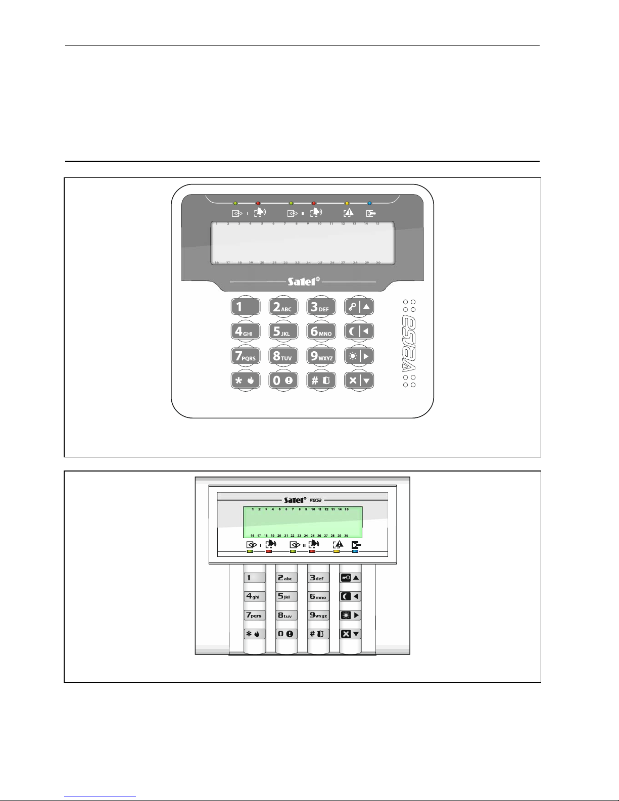
6. Operating the alarm system with LCD keypad.............................................................6
6.1 Keypads description............................................................................................................... 7
6.1.1 LEDs presenting partition and system state..................................................................................7
6.1.2 Display ...........................................................................................................................................8
6.1.3 Keys...............................................................................................................................................9
6.1.4 Built-in proximity card reader.........................................................................................................9
6.1.5 Sound signaling .............................................................................................................................9
6.2 Codes................................................................................................................................... 11
6.2.1 Factory default codes ..................................................................................................................11
6.3 Arming.................................................................................................................................. 11
6.3.1 Arming without partition selection................................................................................................11
6.3.2 Arming with proximity card VERSA-LCDR / VERSA-LCDM-WRL ..............................................11
6.3.3 Arming the selected partition.......................................................................................................12
6.3.4 Quick arming................................................................................................................................12
6.3.5 Arming without delay ...................................................................................................................12
6.3.6 Information about bypassed zones .............................................................................................12
6.3.7 Denial of arming and forced arming ............................................................................................13
6.3.8 Failure of arming procedure ........................................................................................................13
6.4 Disarming and alarm clearing............................................................................................... 14
6.4.1 Disarming and alarm clearing without partition selection ............................................................14
6.4.2 Disarming and alarm clearing with a proximity card VERSA-LCDR / VERSA-LCDM-WRL .......14
6.4.3 Disarming and alarm clearing in selected partition......................................................................14
6.4.4 Viewing the zones which triggered alarm....................................................................................14
6.5 Quick inspection of partition status....................................................................................... 14
6.6 Triggering the alarm from keypad ........................................................................................ 15
6.7 Turning the CHIME on /off.................................................................................................... 15
6.8 User menu............................................................................................................................ 15
6.8.1 Navigating through the menu and running functions...................................................................15
6.8.2 “Step by step” programming method...........................................................................................16
6.8.3 Entering data ...............................................................................................................................16
6.8.4 User functions list ........................................................................................................................17
6.9 Change own code ................................................................................................................ 18
6.10 Users.................................................................................................................................... 18
6.10.1 Adding a user...............................................................................................................................19
6.10.2 User editing..................................................................................................................................24
6.10.3 Removing a user .........................................................................................................................25
6.11 Canceling the telephone messaging .................................................................................... 25
6.12 Zone bypassing.................................................................................................................... 25
6.12.1 Zone inhibiting .............................................................................................................................26
6.12.2 Zone isolating ..............................................................................................................................26
6.13 Viewing the event log ........................................................................................................... 26
6.14 Auto-arming deferment......................................................................................................... 27
6.14.1 Simple auto-arming deferment ....................................................................................................27
6.14.2 Auto-arming deferment by means of function .............................................................................27
6.15 Setting the system time and date ......................................................................................... 27
6.16 Programming the timers....................................................................................................... 27
6.16.1 Programming the weekly schedule..............................................................................................28
6.16.2 Programming an exception..........................................................................................................28

2 VERSA Plus SATEL
6.16.3 Selecting the arming mode......................................................................................................... 28
6.17 Programming the telephone numbers to be notified ............................................................ 28
6.18 Programming codes to acknowledge / clear messaging...................................................... 30
6.19 Checking the troubles / system state................................................................................... 30
6.19.1 Information on system state ....................................................................................................... 30
6.19.2 Trouble handling procedure........................................................................................................ 30
6.19.3 Trouble memory and clearing the trouble memory..................................................................... 30
6.20 Output control ...................................................................................................................... 31
6.20.1 Quick control of outputs.............................................................................................................. 31
6.20.2 Controlling the outputs by means of proximity card VERSA-LCDR / VERSA-LCDM-WRL ....... 31
6.20.3 Controlling the outputs by means of function ............................................................................. 31
6.21 Tests .................................................................................................................................... 31
6.21.1 Zone test..................................................................................................................................... 31
6.21.2 Output test .................................................................................................................................. 32
6.21.3 Checking the level / quality of radio / GSM signal ...................................................................... 32
6.21.4 Starting the manual test transmission ........................................................................................ 32
6.21.5 Telephone reporting test............................................................................................................. 32
6.21.6 Checking the firmware version of control panel ......................................................................... 33
6.21.7 Checking the firmware version of modules................................................................................. 33
6.21.8 Checking the current supply voltage in modules........................................................................ 33
6.21.9 Outputs reset .............................................................................................................................. 33
6.22 Service................................................................................................................................. 33
6.22.1 Defining the service access rules ............................................................................................... 33
6.22.2 Defining the service access time ................................................................................................ 34
7. Operating the alarm system by means of keyfob ......................................................34
7.1 Denial of arming................................................................................................................... 36
7.1.1 Forced arming............................................................................................................................. 36
7.2 Failure of the arming procedure initiated from keyfob.......................................................... 36
8. Operating the alarm system by telephone..................................................................36
8.1 Starting the operating by telephone..................................................................................... 37
8.2 Voice menu.......................................................................................................................... 37
8.3 Ending the operating by telephone ...................................................................................... 39
9. Acknowledgement of voice messaging......................................................................39
10. SMS control...................................................................................................................39
11. VERSA CONTROL application.....................................................................................39
12. Manual update history..................................................................................................41

SATEL VERSA Plus 3
1. Introduction
Thank you for choosing the product offered by the SATEL Company. Wishing you full
satisfaction with the choice you made, we are always ready to provide you with professional
assistance and information on our products.
The SATEL Company is manufacturer of a broad range of devices dedicated for use in
security alarm systems. Further information is available on our website www.satel.eu or at
the points of sale offering our products.
This manual describes various ways of operating the alarm system, except by using the LED
keypad and the touchscreen keypads (INT-TSG and INT-TSH), the description of which can
be found in separate manuals.
It is recommended that that the installers prepare their own user manual for the alarm
system installed by them. The manual must include all changes and modifications in
relation to the factory default settings.
The installer should train the users in the rules of operating the alarm system.
2. Technical reliability of the alarm system
A failure of any component of the alarm system will result in deterioration of the level of
protection. Unfortunately, the devices which are installed outside (e.g. the outdoor sirens) are
exposed to the adverse effects of weather. During storms, the devices connected to the
electrical system or telephone line are vulnerable to damage as a result of atmospheric
discharge.
The control panel is provided with a number of safeguards and automatic diagnostic features
to test the system performance. Detection of irregularities is signaled by the LED on the
keypad. You should immediately respond to such a signal, and, if necessary, consult
the installer.
In addition, some features designed for testing the alarm system are available in the control
panel. They make it possible to check the detectors, sirens, telephone communicators, etc for
correct functioning. Only regular testing and inspection of the alarm system will allow
you to keep a high level of protection against intrusion.
It is recommended that the installer, at the request of the user, carry out periodic
maintenance of the alarm system.
It is in the interest of the user to anticipate and plan in advance the procedures in case an
alarm is set off by the control panel. It is important to be able to verify the alarm, determine its
source and take appropriate actions (e.g. evacuation in the event of a fire alarm).
3. Alarm system operating costs
The control panel can inform the users and the monitoring station about the status of
protected facility. Realization of these functions by means of the phone line or GSM means
financial costs. The amount of the costs incurred depends on the amount of information sent.
A failure of telephone links, as well as an incorrect programming of the control panel, may
result in increased costs (due to making of excessive number of calls).
Please inform the installer, which is a priority: to deliver information at any cost, or to prevent
excessive costs. For example, after an event code has failed to be sent successfully to the
monitoring station, the control panel may repeat attempts every few minutes to send the code
or to cease the attempts to send the code until a next event occurs.

4 VERSA Plus SATEL
4. Glossary
Alarm – reaction of the alarm system to detection by the detectors of an intruder in the
protected area, or to another event within the protected area (e.g. glass pane break, gas
detection, etc.). The alarm can be signaled in keypads, proximity card arm/disarm devices,
or by sirens (during a defined time or until cleared). Additionally, information on the alarm
can be sent to the monitoring station or the user.
Alarm zone – the zone whose violation can result in the alarm being triggered. The alarm
zones can be either instant (violation will trigger the alarm at once) or delayed (violation
will only trigger the alarm after a defined period of time has elapsed, e.g. the entry delay).
Armed mode – the status of alarm system in which zone violation will trigger the alarm.
Code – a sequence of digits that allows the user to operate the alarm system by using
keypad.
Day armed mode – the status in which only some zones in the partition are armed, as
selected by the installer. The installer should indicate the zones to be armed when a user
stays in the protected area, but there is no risk of the zones being violated by the user
during the daytime. If no such zones are indicated by the installer, the user will not be able
to arm the partition in this mode.
Detector – the basic component of alarm system, which analyzes the environment and, if
a situation recognized as a threat occurs, transmits appropriate information to the control
panel (e.g. motion detectors on registering motion, magnetic contacts on opening the
door/window, glass-break detectors on breaking glass pane, gas detectors on sensing
gas, etc.).
Entry delay – time counted from the moment of entry into the protected area, which makes it
possible to disarm the partition before the alarm is triggered.
Entry route – the route which the user must have to follow after entry into the protected area
before being able to disarm the system. It is usually the same as the exit route.
Exit delay – time counted from the moment of starting the arming procedure in the partition,
which makes it possible to leave the protected area before the alarm is triggered.
Exit route – the route which the user must have to take after arming before he leaves the
protected area. It is usually the same as the entry route.
Fire alarm – alarm triggered by fire detectors, or from the keypad, in the event of fire.
Full armed mode – the status in which all zones belonging to the partition are armed.
Installer – the person who has installed and programmed the alarm system.
Medical (auxiliary) alarm – alarm triggered by means of a button, or from the keypad, if it is
necessary to call the medical assistance.
Night armed mode – the status in which only some zones in the partition are armed, as
selected by the installer. The installer should indicate the zones to be armed when a user
stays in the protected area, but there is no risk of the zones being violated by the user at
night. If no such zones are indicated by the installer, the user will not be able to arm the
partition in this mode.
Panic alarm – alarm triggered by means of the panic button, or from the keypad, in case of
a hold-up.
Partition – a part of the protected area, composed of a number of zones. The division into
partitions makes it possible to limit the access to part of the premises to some selected
users, and to arm/disarm the system only in part of the protected area.
Passive transponder – a wireless device which has no power supply of its own, but, under
the action of electromagnetic field, it can emit a signal that enables the device to be
identified. It can have the form of proximity card, proximity tag, etc.

SATEL VERSA Plus 5
Protected area – the area supervised by detectors being part of the alarm system.
Proximity card – a passive transponder that allows the user to operate the alarm system by
means of a proximity card reader (INT-CR and INT-IT proximity card arm/disarm devices
are provided with the reader).
Reporting – reporting events that occurred in the alarm system to the monitoring station. The
information about occurrence of an event can be transmitted via telephone line, Ethernet
network, etc. The companies offering the alarm system monitoring service undertake to
intervene if specific events occur (e.g. alarms, troubles, etc.).
Service code – a code that allows access to the service mode, as well as some functions in
the user menu.
Service technician – the person whose function is to control operability of the installed alarm
system and its components, as well as to eliminate possible problems. These duties can
be fulfilled by the installer or a person assigned by him.
Siren/beacon – a device providing information about alarms or other events in the alarm
system by means of acoustic or optical signaling.
Tamper alarm – reaction of the alarm system to opening the housing of a device which is
part of the alarm system, tearing off the device from the wall, cutting through the alarm
system cables, etc. Actions taken by the alarm system may be similar as in the event of
alarm, however, if the tamper alarm occurs, it is advisable to call in the installer so that he
can make a checkup.
User – a person which can operate the alarm system, using a code, proximity card or remote
control keyfob.
Warning alarm – in some situations, when the alarm criteria are met, the alarm system does
not take up immediately all the actions provided for in the event of alarm. These actions
are postponed, reaction of the system being limited to signaling warning alarm in keypads,
proximity card arm/disarm devices or on indoor sirens/beacons. Thus the user who made
a mistake when entering the protected area (failed to disarm the system before the entry
delay expires), or moving around the area when the day or night armed mode is activated
(violated the armed zone), has some extra time to disarm the system. Contact your
installer to obtain detailed information on the situations when the alarm will be preceded by
warning alarm.
Zone – 1. a separated portion of the protected area that can supervised by a detector or
detectors. 2. the terminals on control panel/expander electronics board to which you can
connect a detector or another device whose state is to be supervised (panic button, siren
tamper contact, power supply output indicating loss of 230 V AC supply, etc.).
Zone bypassing (inhibiting / isolating) – procedure preventing the alarm from being
triggered by the selected zone when it is in the armed mode. Violations of the zone will be
ignored by the control panel.
Zone violation – a change of the zone status to another, different from that defined for the
normal state (e.g. as a result of motion being sensed by the motion detector, gas being
sensed by the gas detector, etc.).
5. Control panel compliance with EN 50131 standard
requirements for Grade 2
If the installer has configured the control panel in compliance with the EN 50131 standard
requirements for Grade 2:
1. The user codes should be composed of at least 5 characters.
2. The amount of information provided in the keypads by means of LEDs, display and sound
signaling is limited.

6 VERSA Plus SATEL
3. The quick arming from keypad (without entering the code) is not available.
4. Arming may be impossible, if one of the situations provided for in the standard occurs
(zone violation, trouble).
How requirements of the standard affect the use of the control panel is described in detail
hereunder.
6. Operating the alarm system with LCD keypad
Fig. 1. VERSA-LCDM keypad (the VERSA-LCDR and VERSA-LCDM-WRL keypads differ
only in some graphic elements on its glass).
Fig. 2. VERSA-LCD keypad.
SATEL offers the following LCD keypads for VERSA Plus control panels:
VERSA-LCDM – hardwired keypad,
VERSA-LCDR – hardwired keypad with built-in proximity card reader,
VERSA-LCDM-WRL – wireless keypad with built-in proximity card reader,

SATEL VERSA Plus 7
VERSA-LCD – hardwired keypad.
The keypads are available in a variety of color options for the display and key backlight. The
color variant is indicated by the additional designation in the keypad name (e.g.
VERSA-LCD-GR – green display and keys backlight; VERSA-LCDM-WH – white display and
keys backlight).
6.1 Keypads description
6.1.1 LEDs presenting partition and system state
LED Color Description
green indicates the partition state (each partition has its own LED)
ON – partition is armed
blinking – exit delay countdown is running in partition
red indicates alarm or alarm memory in the partition (each partition has its
own LED)
The way of presenting the information is shown graphically below.
The information is presented for 2 seconds and repeated ( – LED is
OFF; – LED is ON). The higher position in the list means the higher
priority of the presented status:
– fire alarm,
–burglary alarm,
– warning alarm,
– tamper alarm,
– fire alarm memory,
– burglary alarm memory,
– warning alarm memory,
– tamper alarm memory.
yellow blinking when the system requires user's attention (e.g. because of
a trouble or trouble memory)
The LED goes off, if one or both partitions are armed.
blue indicates the service mode
ON – the service menu is available on the keypad
blinking – the service menu is not available on the keypad (it is either
available on another keypad or has been hidden by the installer)
Information about the armed state can be extinguished after a time period defined by
the installer. Entering the code and pressing the key will display again the
armed state information.
If the GRADE 2 global option is enabled by installer:
the LEDs indicate alarms only after entering the code and pressing the
key,
blinking of the LED means that there is a trouble in the system, some zones
are bypassed, or that there was an alarm.
When programming by means of the “step-by-step” method, the and LEDs present
the number of the current step (see p. 16).

8 VERSA Plus SATEL
When you are using the user menu or service menu, the LED is:
blinking rapidly during navigation through the menus and submenus,
steady on after a function is started.
6.1.2 Display
The display provides a number of data, facilitating communication between the alarm system
and the user. The installer defines how the display will be backlit and selects the information
to be shown on the display screen.
The display can work in normal mode or in zone presentation mode (the modes being
toggled by means of the key). When in the normal mode, the date and time (in installer
defined format) or the keypad name are presented in the upper line of the display. In the
zone presentation mode, symbols are displayed, showing the status of zones available in the
system (where the control panel settings do not provide for detector presence at a zone, the
status of the zone is not displayed). The numbers around the display correspond to the zone
numbers. The symbols illustrate the following zone states (the higher position on the list, the
higher priority of the presented state):
– inhibited (not displayed when armed),
[blinking] – isolated (not displayed when armed),
– long violated (not displayed when armed),
– no violations (not displayed when armed),
– first triggered alarm,
– tampered (2EOL type zone),
– violated,
– tamper memory (2EOL type zone),
– alarm memory,
– normal state.
If the global GRADE 2option is enabled by the installer, switching the display over to
the zone status presentation mode ( key) is impossible.
Irrespective of the selected mode, the occurrence of specific events may result in the
following information being displayed (the higher position = the higher priority of the status
presented):
countdown of auto-arming delay,
countdown of entry delay,
countdown of exit delay,
alarm from zone – the message contains the name of zone which triggered the alarm and
remains displayed until the alarm is cleared (in case of alarm from several zones,
messages about successive alarms are displayed alternately every 2 seconds – use the
or key to scroll them through),
alarm in partition – the message contains the name of partition where the alarm occurred
and remains displayed until the alarm is cleared (if there is alarm in both partitions,
messages about the alarm are displayed alternately every 2 seconds in the first and
second partition – use the or key to scroll them through),
there was a tamper and the service must be called in – the message is displayed until
trouble memory is cleared by a person using the service code (see: “Trouble memory and
clearing the trouble memory” p. 30).

SATEL VERSA Plus 9
If the GRADE 2global option is enabled by the installer, the messages on alarms and
tampers are not displayed.
6.1.3 Keys
The keys bearing digits and letters enable entering the code, as well as data when the
keypad is being used.
Other functions of these keys and the basic function of the other keys are described below.
allows to trigger the medical (aux) alarm (press and hold down for 3 seconds)
allows to turn on/off the CHIME signal in the keypad (press and hold down for
3 seconds)
allows to toggle the LCD keypad display between the normal mode and the zone
state presentation mode (press and hold down for 3 seconds)
allows to:
arm in the full mode [if the system is disarmed and there is no alarm] or disarm
the system and clear the alarm [if the system is armed and/or there is an alarm]
(enter the code and press )
trigger the panic alarm (press and hold down for 3 seconds)
allows to:
open the user menu (enter the code and press )
trigger the fire alarm (press and hold down for 3 seconds)
allows to arm in the full mode (see “Arming”)
allows to arm in the night mode (see “Arming”)
allows to arm in the day mode (see “Arming”)
allows to:
disarm the system and clear the alarm (see “Disarming and alarm clearing”)
quickly check the partition state (press and hold down for 3 seconds)
6.1.4 Built-in proximity card reader
The VERSA-LCDR and VERSA-LCDM-WRL keypads have a built-in proximity card reader.
You can use proximity cards (tags or other 125 kHz passive transponders) to:
– arm the system,
– disarm the system and/or clear alarm,
– toggle the state of the devices connected to the alarm system outputs.
6.1.5 Sound signaling
The installer can disable the sound signaling.
Beeps generated when operating
1 short beep – pressing any number key.
3 short beeps – confirmation of:
– starting the arming procedure (there is exit delay in the partition) or arming (there is no
exit delay in the partition),
– disarming and/or alarm clearing,

10 VERSA Plus SATEL
– selecting the partition which is to be armed or disarmed, or where alarm is to be cleared
– in such a case the keypad is waiting for the code to be entered,
– turning output off,
– turning off the CHIME in the keypad, using the key,
– switching over the display from the normal mode to the zone status presentation mode,
and vice versa, by means of the key.
4 short beeps and 1 long beep – confirmation of:
– turning output on,
– turning on the CHIME in the keypad, using the key.
1 long beep – some zones are bypassed (when arming) or denial of arming (some zones in
the partition are violated or there is a trouble).
2 long beeps – incorrect code / card or pressing the , , , or
key, if not preceded by entering code or selecting a partition.
3 long beeps – refusal to carry out a command (the user does not have the required
authority level or the function is not available).
Beeps generated during programming
1 short beep – pressing any number key.
2 short beeps – entering the user menu, submenu or a function, or going to a next
programming step.
3 short beeps – end of timer parameters editing, exiting the service function on pressing the
key.
4 short beeps and 1 long beep – termination of the user function on pressing the key,
or quitting the service mode.
2 long beeps – exiting the function on pressing the key, or an unavailable function.
Events signaled by sounds
Only installer selected events are signaled.
Duration of the alarm signaling is to be defined by the installer.
If the GRADE 2 option is enabled by installer, the keypad will not signal by sounds any
new troubles and alarms.
5 short beeps – zone violation (CHIME).
Long beep every 3 seconds, followed by a series of short beeps for 10 seconds
and 1 long beep – countdown of exit delay (if the time is shorter than 10 seconds, only
the final sequence of short beeps will be generated).
A sequence of 7 beeps of diminishing duration, repeated every few seconds –
countdown of auto-arming delay.
2 short beeps every seconds – countdown of entry delay.
2 short beeps every 3 seconds – signaling a new trouble.
Short beep every 0.5 seconds – warning alarm.
Continuous beep – alarm.
Long beep every second – fire alarm.

SATEL VERSA Plus 11
6.2 Codes
Operating the alarm system by means of the keypad is possible after entering the code. Only
some functions can be run without the code being entered.
Do not make your code available to other people.
Using an incorrect code three times may:
trigger an alarm,
block the keypad for 90 seconds.
6.2.1 Factory default codes
By default, the following codes are preprogrammed in the control panel:
user 30 code: 1111
service code: 12345
The factory default codes should be changed before you start using your alarm
system (see: “Change own code”).
6.3 Arming
Completion of the steps below will start the arming procedure. The procedure ends when the
exit delay time elapses (if the countdown is completed successfully, the system becomes
armed – see also “Failure of arming procedure” p. 13). If the exit delay time is 0, the system
becomes armed instantly.
You can change the arming mode, which means you do not have to disarm the system to set
the partition to another arming mode. In the case of alarm, changing the arming mode or re-
activating the same arming mode will result in clearing the alarm (it does not apply to the
quick arming mode).
The day/night arming modes are available if the installer has defined which zones are
to be active in this armed mode.
If exit delay is programmed for a partition, you can leave the partition through the exit
route without triggering alarm after the partition arming procedure has started. The
exception is when the partition is armed without exit delay.
6.3.1 Arming without partition selection
Enter the code, and then press:
- to arm in full mode,
- to arm in day mode,
- to arm in night mode.
The partitions to which you have access will be armed.
6.3.2 Arming with proximity card VERSA-LCDR / VERSA-LCDM-WRL
You can use one of the following methods to arm the system (consult with the installer which
method is to be used):
– bring the card close to the keys and move it away,
– bring the card close to the keys and hold it there for about 3 seconds.
The partitions to which you have access will be armed in full mode.

12 VERSA Plus SATEL
The reader in VERSA-LCDM-WRL keypad is enabled:
for 5 seconds after disappearance of the connection establishment message (the
message is displayed after the keypad is activated by pressing any key),
for 20 seconds after pressing the and keys simultaneously.
6.3.3 Arming the selected partition
1. Indicate the partition which is to be armed (press one of the keys: - partition 1;
- partition 2).
2. Select the arming mode (press one of the keys: - full arming; - day arming;
- night arming). Backlight of the keys will start blinking, which indicates that the
code must be entered.
3. Enter the code.
4. Press the key or press again the key corresponding to the selected arming mode.
When the quick arming is available, the steps 3 and 4 are skipped.
6.3.4 Quick arming
The installer may permit arming without entering the code.
1. Indicate the partition(s) to be armed (press one of the keys: - partition 1; -
partition 2; or - both partitions).
2. Select the arming mode (press one of the keys: - full arming; - day arming;
- night arming).
You can switch the arming mode from the night mode to the full mode and from the
day mode to the full mode without entering the code. Otherwise, you will have to enter
the code – see “Arming the selected partition”.
The installer can configure the system so that the quick arming can be impossible, if
there is a violated zone in the partition, or a trouble has occurred in the system.
6.3.5 Arming without delay
When arming the system using one of the above mentioned methods, press and hold down
the arming mode selection key ( , or ) for about 3 seconds. The system will
become armed without delay, i.e. the delayed zones will act as instant ones (without any
exit/entry delay time).
In the day armed mode, the entry delay countdown may run, if the control panel is so
configured by the installer.
6.3.6 Information about bypassed zones
During an arming attempt you may get a message about bypassed zones in the partition. The
information will be displayed, if:
the control panel has been suitably configured by the installer,
you have the INSPECTION right.
The message is displayed in the following form:
“Bypassed zones 1=Arm 4=Bypasses” – if you have the ZONE INHIBITION right. You can:
– press the key to cancel the arming,
– press the key to proceed with the arming,
– press the key to start the INHIBIT function (see: “Zone inhibiting” p. 26).

SATEL VERSA Plus 13
“Bypassed zones 1=Arm” – if you don’t have the ZONE INHIBITION right. You can:
– press the key to cancel the arming,
– press the key to proceed with the arming.
6.3.7 Denial of arming and forced arming
The installer can configure the control panel so that initiating the arming procedure is
impossible, if:
in the partition to be armed, at least one zone that must not be violated during arming (the
PRIORITY option has been enabled for the zone by the installer) is violated,
in the partition to be armed, at least one alarm zone is violated beyond the exit route,
there is trouble in the system.
If you have the INSPECTION right, you will be informed about the cause of refusal to arm the
system (the order of message descriptions corresponds to their priority):
“Zone [zone number] violat.” – a zone with enabled PRIORITY option is violated. If two or
more such zones are violated, the indicator will be flashing on the display. To scroll
through the list of violated zones, use the and keys. You can:
– press the key to cancel the arming,
– press the key to inhibit the violated zone (you must have the ZONE INHIBITION
right). A message will be displayed, prompting you to confirm the command to inhibit the
zone (press to inhibit the zone, or to cancel inhibiting the zone).
The system can be armed after eliminating the cause of the zone violation, or after
bypassing the zone.
“Violated zones 1=Ok 2=Check” – an alarm zone outside of the exit route is violated. You
can:
– press the key to cancel the arming,
– press the key to force the arming,
– press the key to check which zone is violated. If two or more such zones are
violated, the indicator will be flashing on the display. To scroll through the list of
violated zones, use the and keys. If you have the ZONE INHIBITION
permission, you will be able inhibit the violated zone by pressing . A message will
be displayed, prompting you to confirm the command to inhibit the zone (press to
inhibit the zone, or to cancel inhibiting the zone).
“Troubles 1=Ok 2=Check” – there is a trouble in the system. You can:
– press the key to cancel the arming,
– press the key to force the arming,
– press the key to view the trouble log – the 7. SYSTEM STATE function will start
(see: “Checking the troubles / system state” p. 30).
Information on the forced arming is written into the event log.
6.3.8 Failure of arming procedure
The installer can configure the alarm system in such a manner that it will not be armed, if at
the moment of completing the exit delay countdown:
there is a violated zone in partition which was not violated when the arming procedure was
started,
there is a trouble which did not exist when the arming procedure was started.

14 VERSA Plus SATEL
If the arming has been forced, the control panel will ignore violations and troubles
which took place after starting the arming procedure.
6.4 Disarming and alarm clearing
Disarming and alarm clearing are carried out in the same way, the procedures being
interconnected. If the partition is armed and an alarm is triggered in it, then disarming will
also mean alarm clearing.
In order to clear the alarm without disarming the partition, arm again the partition in the
same mode (see: “Arming” p. 11).
6.4.1 Disarming and alarm clearing without partition selection
Enter the code and then press the key. Disarming / alarm clearing will take place in the
partitions to which you have access.
6.4.2 Disarming and alarm clearing with a proximity card VERSA-LCDR /
VERSA-LCDM-WRL
Bring the card close to the keys and move it away. Disarming / alarm clearing will take place
in the partitions to which you have access.
The reader in VERSA-LCDM-WRL keypad is enabled:
for 5 seconds after disappearance of the connection establishment message (the
message is displayed after the keypad is activated by pressing any key),
for 20 seconds after pressing the and keys simultaneously.
6.4.3 Disarming and alarm clearing in selected partition
1. Indicate partition which is to be disarmed and/or where alarm is to be cleared (press one
of the keys: - partition 1; - partition 2).
2. Press the key. Backlight of the keys will start blinking, which indicates that the code
must be entered.
3. Enter the code.
4. Press the or key.
6.4.4 Viewing the zones which triggered alarm
Having cleared the alarm, you can check which zones triggered the alarm (this does not
apply to the TMP zone of the control panel). The information will be available until viewing the
zones or arming the system.
1. Enter the code and press .
2. The “View cleared zones? 1=Yes” will appear on the display. Press .
3. The list of zones which triggered the alarm will be displayed.
4. Having viewed the list, press (the user menu will be displayed).
6.5 Quick inspection of partition status
If such an option is provided by the installer, pressing and holding down the key for
about 3 seconds will display information on the partition state (whether it is armed and what
type of arming mode is set). At the same time, the LED will come on. In the upper line,
a message about the first partition state is displayed, and in the lower line – about the second
partition state.

SATEL VERSA Plus 15
To terminate the function of partition state presentation, press . The keypad will quit the
function automatically after 2 minutes.
6.6 Triggering the alarm from keypad
The installer can permit triggering alarms from the keypad. To trigger an alarm, do the
following:
fire alarm – press for approx. 3 seconds,
medical (auxiliary) alarm – press for approx. 3 seconds,
panic alarm – press for approx. 3 seconds. The installer defines whether the loud
panic alarm (setting off the loud alarm signal) or the silent panic alarm (without the loud
signal) will be triggered.
6.7 Turning the CHIME on /off
The CHIME is five short sounds by means of which the keypad will inform you e.g. that
a door / window is open, when the system is disarmed. The installer defines which zones of
the alarm system can trigger the CHIME and whether it can be turned on/off by the users.
Press and hold down for about 3 seconds to turn on or off the CHIME signaling.
6.8 User menu
Enter the code and press to get access to the user menu. The functions you can run
will be displayed. The list of available functions depends on your rights, as well as on the
state and configuration of the system.
In order to quit the function and/or user menu, press . The keypad will quit the menu
automatically, if 2 minutes have elapsed since the last keypress.
6.8.1 Navigating through the menu and running functions
Using the arrow keys
1. Using the and keys, find the required submenu or function. The currently
selected submenu or function is indicated by the cursor on the left (the submenu
indicating cursor: ; the function indicating cursor: ).
2. Press or to open a submenu or run a function (use the key to go back
to the previous menu/submenu).
Using the digit shortcuts
All submenus and functions are numbered. In order to enter a submenu, just press the key
with number corresponding to the submenu number. In order to start a function, press the
key with number corresponding to the function number, and then . You can quickly start
the selected function by entering at once a sequence of some digits (corresponding to the
consecutive submenu numbers and the function number) and pressing .
For example, to start the zone inhibiting function, enter the user menu and then press
, where:
- entering the 4. BYPASSES submenu,
- running the 1. INHIBIT function.
Remember that the sequence of digits which starts a function e.g. from the main menu
level will not start the same function from the submenu level.

16 VERSA Plus SATEL
6.8.2 “Step by step” programming method
In case of some functions (e.g. adding and editing users, configuring timers, etc.), the
programming is effected by using the “step by step” method. After calling the function and
selecting the item to be configured from the list, the first parameter available for programming
will be displayed. After pressing , you will go on to programming another parameter (if
you have entered some changes, they will be saved). After all parameters have been
configured, you will either return to the selection list or exit the user menu, depending on the
function. The and LEDs of the first and second partition show the number of
programming step (see: table 1). Some programming steps may be sometimes not available.
LED status
Number of
programming step
1
2
3
4
5
6
7
8
9
10
Table 1. The manner of indicating the programming step
(- LED OFF; - LED ON).
6.8.3 Entering data
The changes entered will be saved after pressing the key. Use the key to quit
the function without saving changes.
Entering digits
To enter digits, use the numeric keys.
Entering hexadecimal characters
To enter digits, use the numeric keys, and to enter characters from A to F, use the and
keys (keep pressing the key until the required character appears).
Entering names
The characters that can be entered by using the keys are presented in Table 2. Keep
pressing the key until the required character appears. Long press the key to display the digit
assigned to it.

SATEL VERSA Plus 17
Key Characters available after next keystroke
! ? ' ` " { } $ % & @ \ ^ | # 1
abc2
def3
ghi4
jkl5
mno6
pqrs7
t u v 8
wxyz9
. , : ; + - / = _ < > ( ) [ ] 0
Table 2. Characters available when entering names. The upper case letters are available
under the same keys (to change the letter case, press ).
Shown on the left side in the upper line of the display is information about the letter case:
[Abc], [ABC] or [abc] (it will be displayed after pressing any key and will be visible for a few
seconds after the last keystroke).
The key moves the cursor to the right, and the key – to the left. The key
deletes the character on the left side of the cursor.
6.8.4 User functions list
Shown in square brackets are key sequences that enable calling the given submenu or
starting the given function from the main menu level. The functions that are only available
after entering the service code have been specially highlighted (white text against black
background). The access to other functions depends on the user rights. Highlighted with
a frame are the functions which are available or change the operating mode, if the GRADE 2
option has been enabled by the installer.
[1#] 1. Change code changing own code
[2] 2. Users
[21#] 1. New user adding new user
[22#] 2. Edit user editing user
[23#] 3. Remove user removing user
[3#] 3. Abort v.msg. canceling telephone messaging
[4] 4. Bypasses
[41#] 1. Inhibit inhibiting zones
[42#] 2. Isolate isolating zones
[5#] 5. Event log viewing events
[5#1#] 1. All viewing all events
[5#2#] 2. Grade2 backup viewing events required for Grade 2
[6] 6. Settings
[61#] 1. A-arm defer. auto-arming deferment
[62#] 2. RTC clock programming the clock

18 VERSA Plus SATEL
[63#] 3. Timers programming the timers
[64#] 4. Tel. numbers programming telephone numbers to be notified
[65#] 5. Msg.clr.codes programming codes to acknowledge / clear messaging
[7#] 7. System state checking troubles / checking partition, alarm, trouble status
[8#] 8. Control controlling the outputs
[9] 9. Tests
[91#] 1. Zone test starting zone test
[92#] 2. Output test starting output test
[93#] 3. Wrls/GSM sig. checking radio / GSM signal level
[94#] 4. Manual MS tst starting manual test transmission
[95#] 5. MS1 test test of telephone reporting to station 1
[96#] 6. MS2 test test of telephone reporting to station 2
[97#] 7. VERSA version checking firmware version of control panel
[98#] 8. Expander ver. checking firmware version of system modules
[99#] 9. Supply volt. checking current supply voltage in modules
[90#] 0. Outputs reset deactivating outputs / activating 21. DETECTORS RESETTING output
[0] 0. Service
[00#] 0. Service mode starting service mode
[01#] 1. Start DwnlTEL starting programming via analog telephone communicator
[02] 2. Start DwnlGSM
[021#] 1. GSM audio starting programming via GSM communicator (300 bps)
[022#] 2. GSM CSD starting programming via GSM communicator (CSD)
[03#] 3. Start DwnlUSB starting local programming
[04#] 4. FinishDwnlUSB finishing local programming
[05#] 5. Serv. access defining service code access rules
[06#] 6. Access time defining service code access time
[07#] 7. ETHM-1DLOADXstarting programming via Ethernet
[08#] 8. GPRSDLOADX starting programming via GPRS
6.9 Change own code
1. Enter the user menu and press in turn .
2. Enter the new code, and then press .
6.10 Users
There can be up to 30 users in the system. A person using the service code (installer
/ service technician), who is an additional user, has a special status, but his/her access can
be limited (see: “Defining the service access rules” p. 33 and “Defining the service access
time” p. 34).
Other manuals for Versa Plus
5
Table of contents
Other Satel Control Panel manuals

Satel
Satel Versa Plus Owner's manual

Satel
Satel CA-10 User manual

Satel
Satel Integra 24 User manual

Satel
Satel CA10 plus User manual

Satel
Satel PERFECTA-T User guide

Satel
Satel CA-5 User guide

Satel
Satel VERSA IP Owner's manual

Satel
Satel Integra Series User guide

Satel
Satel Versa Owner's manual

Satel
Satel PERFECTA-IP-32 User guide

Satel
Satel INTEGRA Plus User manual

Satel
Satel Integra Series User manual

Satel
Satel CA-5 User manual

Satel
Satel PERFECTA User manual

Satel
Satel INTEGRA Plus Owner's manual

Satel
Satel CA-6-P User guide

Satel
Satel Integra Series User guide

Satel
Satel INTEGRA Plus User manual

Satel
Satel CA-10 Owner's manual

Satel
Satel PERFECTA User manual