manuals.online logo
Brands
  1. Home
  2. •
  3. Brands
  4. •
  5. Sauder
  6. •
  7. Indoor Furnishing
  8. •
  9. Sauder Boone Mountain 416971 User manual

Sauder Boone Mountain 416971 User manual

NOTE: THIS INSTRUCTION
BOOKLET CONTAINS IMPORTANT
SAFETY INFORMATION.
PLEASE READ AND KEEP FOR
FUTURE REFERENCE.
Enlish p 1-26
Français p 27-29
Español p 20-32
Lot # 361887 07/25/14
Purchased: __________________
Be sure to ive us a rin before
makin any returns. 1-800-523-3987
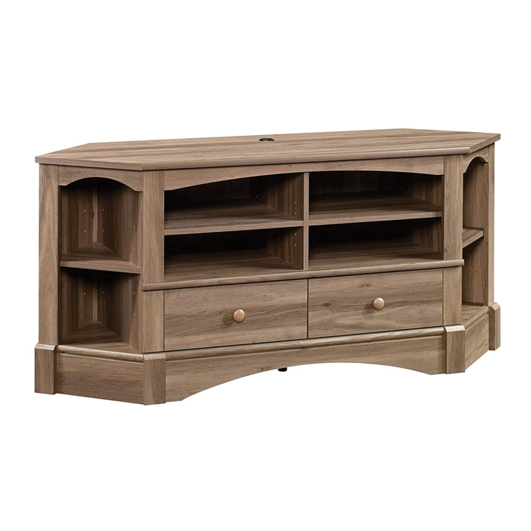
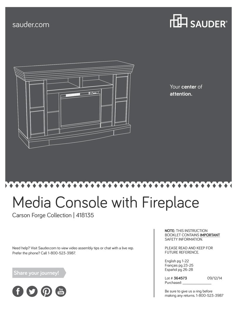
Anywhere Console
Boone Mountain Collection | Model 416971
Need help? Visit Sauder.com to view video assembly tips or chat with a live rep.
Prefer the phone? Call 1-800-523-3987.
Share your journey!
sauder.com
It stands. You sit.
A thin of beauty,
this one.
Table of Contents Assembly Tools Required
3
4
5-26
27-29
30-32
33-34
35
Part Identification
Hardware Identification
Assembly Steps
Français
Español
Safety
Warranty
Hammer
Not actual size
No. 2 Phillips Screwdriver
Tip Shown Actual Size
Use of a TV that is too heavy or lare is hazardous. A TV that is too heavy will create a risk of a tip-over that can cause severe injury or
death. A TV that is too lare for the available space miht be accidentally pushed or bumped o the furniture, or subject to tip-over.
• Check the size and weiht of your TV. Compare it to the diaram below – before you begin assembly!
• This Sauder unit is desined for use with televisions weihin less than 70 pounds. Never use with a TV that weihs more.
• The size of the television, front-to-back and side-to-side, must fit within the space defined in the diaram.
• Never place the front ede of the TV past the front ede of the TV support shelf (or stop moldin – if equipped)
• Never allow the sides of the TV to extend past the side edes of the TV support surface.
• If the TV has a CRT picture tube, the picture tube cone may extend past the rear of the support shelf.
• Be sure to apply the warnin label as instructed in the last assembly step. The label provides important safety related information.
WARNING
!
70 lbs.
70 lbs.
16-1/2"
16-1/2"
48"
48"
Skip the power trip.
This time.
416971 www.sauder.com/servicesPae 2
Part Identification
åWhile not all parts are labeled, some of the parts will have a label or an inked letter on the ede
to help distinuish similar parts from each other. Use this part identification to help identify similar parts.
A RIGHT END (1)
B LEFT END (1)
C UPRIGHT (1)
D BACK UPRIGHT (1)
E TOP (1)
F BOTTOM (1)
G SHELF (1)
H LOWER SHELF (1)
I BACK (2)
J RIGHT FRONT LEG (1)
K LEFT FRONT LEG (1)
L RIGHT FRONT SIDE LEG (1)
M LEFT FRONT SIDE LEG (1)
N RIGHT REAR LEG (1)
O LEFT REAR LEG (1)
P RIGHT REAR SIDE LEG (1)
Q LEFT REAR SIDE LEG (1)
R RIGHT DRAWER FRONT (1)
S LEFT DRAWER FRONT (1)
T SHELF MOLDING (1)
U BOTTOM MOLDING (1)
V RIGHT TOP MOLDING (1)
W LEFT TOP MOLDING (1)
X TOP MOLDING (1)
D16 RIGHT DRAWER SIDE (2)
D17 LEFT DRAWER SIDE (2)
D73 DRAWER BACK (2)
D720 DRAWER BOTTOM (2)
Now you know
our ABCs.
416971www.sauder.com/services Pae 3
D16
A
B
C
D
E
F
G
H
I
J
K
L
M
N
O
P
Q
S
T
U
V
W
X
D720
D73
D17
D16
R
D720
D73
D17
I
Hardware Identification
åScrews are shown actual size. You may receive extra hardware with your unit.
416971 www.sauder.com/servicesPae 4
(Refer to step 22 for proper
location and application)
WARNING LABEL - 1
2L
WARNING
Never use this furniture with a TV that is too
large or too heavy. Severe injury or death
can occur.The TV and furniture will be
unstable and may tip.
-The TV must less than 70 lbs.
-The base of the TV must be able to sit
completely on this shelf.
-Refer to instruction book for complete
safety information.
Note: This is a permanent label. Do not try
to remove. Surface will be damaged.
02/ 02 269224
BB LEFT DRAWER SLIDE - 2LEFT CABINET RAIL - 2
Z
RIGHT CABINET RAIL - 2
YRIGHT DRAWER SLIDE - 2
AA
BLACK 1-1/8" PAN HEAD SCREW - 2
9S
15S SILVER 5/8" MACHINE SCREW - 4
HIDDEN CONNECTOR - 6
9F
CONNECTOR SCREW - 6
8S
BLACK 1-7/8" FLAT HEAD SCREW - 10
2S
CAM COVER - 6
13P SCREW COVER - 8
18P
3S GOLD 5/16" FLAT HEAD SCREW - 16
METAL PIN - 2
1R
10A SLIDE CAM - 4
NAIL - 20
1N
30S BLACK 1-9/16" FLAT HEAD SCREW - 8
HIDDEN CAM - 36
1F CAM DOWEL - 30
2F
CAM SCREW - 6
20F PULL - 2
103K
Step 1 Look for this icon. It means a
video assembly tip is available at
www.sauder.com/services/tips
416971www.sauder.com/services Pae 5
å Assemble your unit on a carpeted floor or on the empty
carton to avoid scratchin your unit or the floor.
å Use your hammer to tap four HIDDEN CONNECTORS with
SCREWS into the ENDS (A and B).
å Repeat this step for the FRONT SIDE LEGS (L and M).
Step 2
9F
(6 used)
8S
9F
A
å Insert a CONNECTOR SCREW (8S) into each
HIDDEN CONNECTOR (9F).
B
Scan this QR code or go to this address:
http://qr.sauder.com/?ID=1495
to watch a video on how to assemble your unit.
Step 3
å Push twenty-eiht HIDDEN CAMS (1F) into the UPRIGHT (C),
TOP (E), BOTTOM (F), SHELVES (G and H), and REAR LEGS (N
and O). Then, insert the metal end of a CAM DOWEL (2F) into
each HIDDEN CAM.
416971 www.sauder.com/servicesPae 6
Arrow
1F
2F
(28 used)
Arrow
1F
2F
Insert the metal end of the CAM
DOWEL into the HIDDEN CAM.
Arrow
Do not tihten the HIDDEN CAMS in this step.
C
E
F
H
N
O
G
Arrow
1F
2F
å Push two HIDDEN CAMS (1F) into the REAR SIDE LEGS (P and Q).
Then, insert the metal end of a CAM DOWEL (2F) into each
HIDDEN CAM.
å Push six HIDDEN CAMS (1F) into the FRONT SIDE LEGS (L and M).
Step 4
416971www.sauder.com/services Pae 7
Arrow
The arrow in the HIDDEN
CAM must point toward the
hole in the ede of the board.
Hole
Arrow
1F
2F
(2 used)
Do not insert CAM
DOWELS into this part.
Do not insert CAM
DOWELS into this part.
Arrow
1F
L
M
P
Q
Do not tihten the HIDDEN CAMS in this step.
(8 used)
1F
Arrow
Step 5
å Turn six CAM SCREWS (20F) into the
FRONT LEGS (J and K).
416971 www.sauder.com/servicesPae 8
20F
Remember:
Rihty tihty.
Lefty loosey.
J
K
å Fasten the RIGHT CABINET RAILS (Y) to the RIGHT END (A)
and UPRIGHT (C). Use four GOLD 5/16" FLAT HEAD
SCREWS (3S) throuh holes #1 and #3.
å NOTE: The CABINET RAILS are marked "CABINET RIGHT"
and "CABINET LEFT" for easy identification.
å Turn the UPRIGHT (C) over and fasten the LEFT CABINET
RAILS (Z) to the LEFT END (B) and other surface of the
UPRIGHT (C). Use four GOLD 5/16" FLAT HEAD
SCREWS (3S) throuh holes #1 and #3.
Step 6
416971www.sauder.com/services Pae 9
1
2
3
3
2
1
Z
Y
Roller end
Roller end
GOLD 5/16" FLAT HEAD SCREW
(8 used in this step)
3S
Finished ede
Z
Y
1
2
3
1
2
3
Roller end
Roller end
C
Surface with
HIDDEN CAMS
Surface without
HIDDEN CONNECTORS
Surface without
HIDDEN CONNECTORS
A
B
Ede with HIDDEN
CONNECTORS
Ede with HIDDEN
CONNECTORS
Step 7
å Fasten the TOP MOLDINGS (V, W, and X) to the TOP (E).
Tihten eiht HIDDEN CAMS.
416971 www.sauder.com/servicesPae 10
Start Tighten
Arrow
Minimum
190 derees
Caution
Risk of damae or
injury. HIDDEN CAMS
must be completely
tihtened. HIDDEN
CAMS that are not
completely tihtened
may loosen, and parts
may separate. To
completely tihten:
Arrow
Maximum
210 derees
W
E
X
V
Surface with HIDDEN CAMS
These surfaces are not even.
å Fasten the FRONT SIDE LEGS (L and M) to the FRONT
LEGS (J and K). Tihten six HIDDEN CAMS.
Step 8
416971www.sauder.com/services Pae 11
1
2
J
K
Surface with HIDDEN CAMS
Surface without HIDDEN CAMS
L
M
These holes must be here.
End with HIDDEN CONNECTOR
Step 9
å Slide the BOTTOM MOLDING* (U) onto the notched ede
of the BOTTOM (F).
å Slide the SHELF MOLDING* (T) onto the notched ede of
the SHELF (G).
å *U.S. Patent No. 5,499,886
416971 www.sauder.com/servicesPae 12
Slide the SHELF MOLDING (T) onto
the notched ede of the SHELF (G).
Notched ede
Notched ede
Slide the BOTTOM MOLDING (U) onto
the notched ede of the BOTTOM (F).
F
U
G
T
Surface with HIDDEN CAMS
å Fasten the ENDS (A and B) to the LOWER SHELF (H).
Tihten four HIDDEN CAMS.
Step 10
416971www.sauder.com/services Pae 13
Arrow
Minimum
190 derees
Maximum
210 derees
H
B
A
Surface with HIDDEN CAMS
Ede with HIDDEN
CONNECTORS
Ede with HIDDEN
CONNECTORS
Surface
with
HIDDEN
CONNECTORS
Surface without
HIDDEN CONNECTORS
Do not stand the unit upriht without the
BACK fastened. The unit may collapse.
Caution
Ede without hole
Step 11
å Fasten the UPRIGHT (C) to the LOWER SHELF (H).
Tihten two HIDDEN CAMS.
416971 www.sauder.com/servicesPae 14
Arrow
Minimum
190 derees
Maximum
210 derees
H
B
A
Finished ede
C
Surface with
HIDDEN CAMS
å Fasten the BOTTOM (F) to the ENDS (A and B). Tihten
four HIDDEN CAMS.
å Fasten the BOTTOM (F) to the UPRIGHT (C). Use two
BLACK 1-7/8" FLAT HEAD SCREWS (2S).
Step 12
416971www.sauder.com/services Pae 15
Arrow
Minimum
190 derees
Maximum
210 derees
BLACK 1-7/8" FLAT HEAD SCREW
(2 used in this step)
2S
U
B
A
C
F
Surface with HIDDEN CAMS
Step 13
å Fasten the FRONT SIDE LEGS (L and M) to the TOP (E).
Tihten two HIDDEN CONNECTORS.
416971 www.sauder.com/servicesPae 16
How to use the HIDDEN CONNECTOR
To fasten two parts together using the
HIDDEN CONNECTORS, insert your
screwdriver, at an angle, into the slot in the
HIDDEN CONNECTOR. While pushing the
screw into the hole of the adjoining part,
turn the screwdriver clockwise to tighten.
E
L
M
Surface with HIDDEN CAMS
These holes should be here.
Don't worry. It isn't
Rome. This can be built
in a day.
å Fasten the SHELF (G) to the FRONT SIDE LEGS (L
and M). Tihten two HIDDEN CAMS.
Step 14
416971www.sauder.com/services Pae 17
Arrow
Minimum
190 derees
Maximum
210 derees
G
L
M
Surface with HIDDEN CAMS
This hole should be here.
Step 15
å Fasten the ENDS (A and B) to the FRONT LEGS (J and K).
Tihten four HIDDEN CONNECTORS.
416971 www.sauder.com/servicesPae 18
B
A
J
K
These holes should be here.
å Fasten the REAR SIDE LEGS (P and Q) to the TOP (E) and
SHELF (G). Tihten four HIDDEN CAMS.
å Fasten the REAR SIDE LEGS (P and Q) to the TOP
MOLDINGS (V and W). Use two BLACK 1-1/8" PAN
HEAD SCREWS (9S).
Step 16
416971www.sauder.com/services Pae 19
G
E
P
V
Q
W
Arrow
Minimum
190 derees
Maximum
210 derees
Surface with HIDDEN CAM
Surface without HIDDEN CAM
BLACK 1-1/8" PAN HEAD SCREW
(2 used in this step)
9S
Step 17
å Insert the CAM DOWELS in the REAR LEGS (N and O) into the
REAR SIDE LEGS (P and Q). Do not tihten the HIDDEN CAMS at
this time.
å Fasten the REAR LEGS (N and O) to the ENDS (A and B). Use four
BLACK 1-7/8" FLAT HEAD SCREWS (2S).
å NOTE: Start each SCREW a few turns before completely
tihtenin any of them.
å Now, tihten the six HIDDEN CAMS in the REAR LEGS (N and O).
416971 www.sauder.com/servicesPae 20
Arrow
Minimum
190 derees
Maximum
210 derees
P
Q
Surface with
HIDDEN CAMS
N
Surface with
HIDDEN CAMS
O
These holes should be here.
BLACK 1-7/8" FLAT HEAD SCREW
(4 used in this step)
2S
B
A

This manual suits for next models

1

Other Sauder Indoor Furnishing manuals
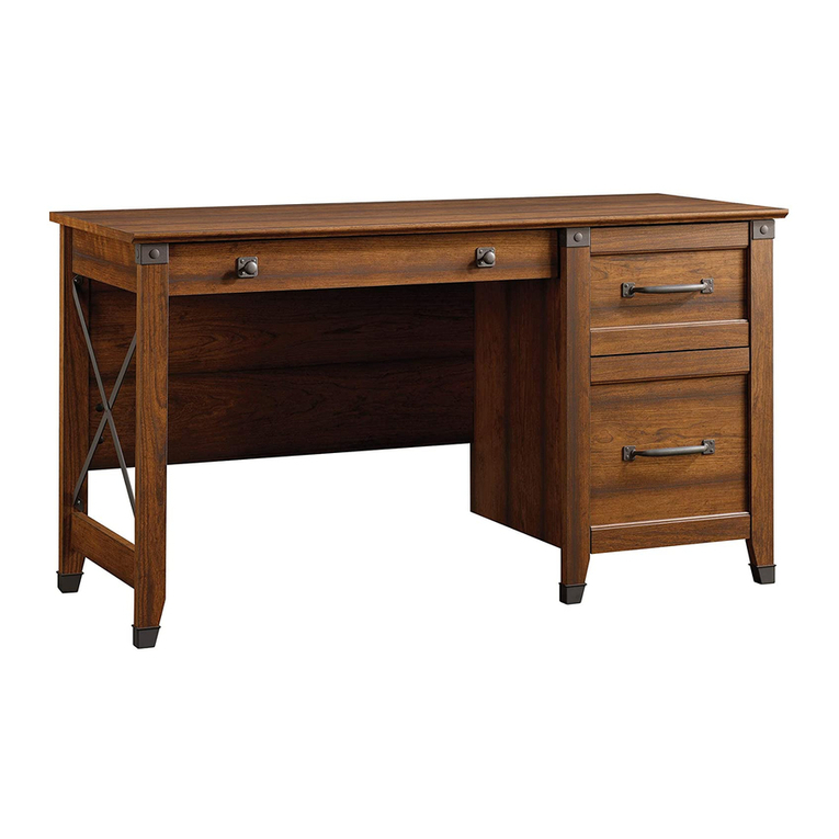
Sauder 420456 User manual

Sauder

Sauder 420456 User manual

Sauder Englewood 426909 User manual

Sauder

Sauder Englewood 426909 User manual

Sauder 418735 User manual

Sauder

Sauder 418735 User manual

Sauder Portage Park 426293 User manual

Sauder

Sauder Portage Park 426293 User manual

Sauder Transit 414417 User manual

Sauder

Sauder Transit 414417 User manual

Sauder Summit Station 425014 User manual

Sauder

Sauder Summit Station 425014 User manual

Sauder Palladia Collection Credenza 412079 User manual

Sauder

Sauder Palladia Collection Credenza 412079 User manual

Sauder Avenue Eight 416514 User manual

Sauder

Sauder Avenue Eight 416514 User manual

Sauder Boone Mountain 416598 User manual

Sauder

Sauder Boone Mountain 416598 User manual

Sauder Harbor View 423661 User manual

Sauder

Sauder Harbor View 423661 User manual

Sauder Shoal Creek 422191 User manual

Sauder

Sauder Shoal Creek 422191 User manual

Sauder Whitaker Point 429374 User manual

Sauder

Sauder Whitaker Point 429374 User manual

Sauder Lateral File 107302 User manual

Sauder

Sauder Lateral File 107302 User manual

Sauder Office Port Series User manual

Sauder

Sauder Office Port Series User manual

Sauder 418647 User manual

Sauder

Sauder 418647 User manual

Sauder Hudson Court 425833 User manual

Sauder

Sauder Hudson Court 425833 User manual

Sauder Barrister Lane 422268 User manual

Sauder

Sauder Barrister Lane 422268 User manual

Sauder 409086 User manual

Sauder

Sauder 409086 User manual

Sauder 419321 User manual

Sauder

Sauder 419321 User manual

Sauder Worksense 427836 User manual

Sauder

Sauder Worksense 427836 User manual

Sauder Cannery Bridge 429414 User manual

Sauder

Sauder Cannery Bridge 429414 User manual

Sauder SmartCenter 422196 User manual

Sauder

Sauder SmartCenter 422196 User manual

Sauder Clifford Place 433364 User manual

Sauder

Sauder Clifford Place 433364 User manual

Sauder Cannery Bridge 431315 User manual

Sauder

Sauder Cannery Bridge 431315 User manual

Popular Indoor Furnishing manuals by other brands

Wayfair Hall Tree Product instructions

Wayfair

Wayfair Hall Tree Product instructions

kupper 12250 Assembly instruction

kupper

kupper 12250 Assembly instruction

Forte JWS928E4 Assembling Instruction

Forte

Forte JWS928E4 Assembling Instruction

QABA 312-101V80 manual

QABA

QABA 312-101V80 manual

Emmezeta TORINO Assembly instructions

Emmezeta

Emmezeta TORINO Assembly instructions

JOCCA 2105 instruction manual

JOCCA

JOCCA 2105 instruction manual

Vauth-Sagel VS ADD Iron manual

Vauth-Sagel

Vauth-Sagel VS ADD Iron manual

Axor Uno Specification sheet

Axor

Axor Uno Specification sheet

RH Teen LAGUNA FULL QUEEN PLATFORM BED manual

RH Teen

RH Teen LAGUNA FULL QUEEN PLATFORM BED manual

Alpine Peacock BVK608A owner's manual

Alpine

Alpine Peacock BVK608A owner's manual

HULALA HOME SCBSD0531 Assembly instructions

HULALA HOME

HULALA HOME SCBSD0531 Assembly instructions

Polini kids Marvel 1005 manual

Polini kids

Polini kids Marvel 1005 manual

World Market JOZY 507802 Assembly instructions

World Market

World Market JOZY 507802 Assembly instructions

Extremis dirk wynants PONTSUN Assembly instructions

Extremis

Extremis dirk wynants PONTSUN Assembly instructions

ApexDesk Elite Series Assembly guide

ApexDesk

ApexDesk Elite Series Assembly guide

Wallbeds Australia 1300 663 660 Assembly instructions

Wallbeds Australia

Wallbeds Australia 1300 663 660 Assembly instructions

Kring OREK231 Assembling Instruction

Kring

Kring OREK231 Assembling Instruction

Cello B600 instruction manual

Cello

Cello B600 instruction manual

manuals.online logo
manuals.online logoBrands
  • About & Mission
  • Contact us
  • Privacy Policy
  • Terms and Conditions

Copyright 2025 Manuals.Online. All Rights Reserved.