manuals.online logo
Brands
  1. Home
  2. •
  3. Brands
  4. •
  5. Sauder
  6. •
  7. Indoor Furnishing
  8. •
  9. Sauder Edge Water 409047 User manual

Sauder Edge Water 409047 User manual

NOTE: THIS INSTRUCTION
BOOKLET CONTAINS IMPORTANT
SAFETY INFORMATION.
PLEASE READ AND KEEP FOR
FUTURE REFERENCE.
English pg 1-22
Français pg 23-25
Español pg 26-28
Lot # 387060 12/22/15
Purchased: __________________
Be sure to give us a ring before
making any returns. 1-800-523-3987
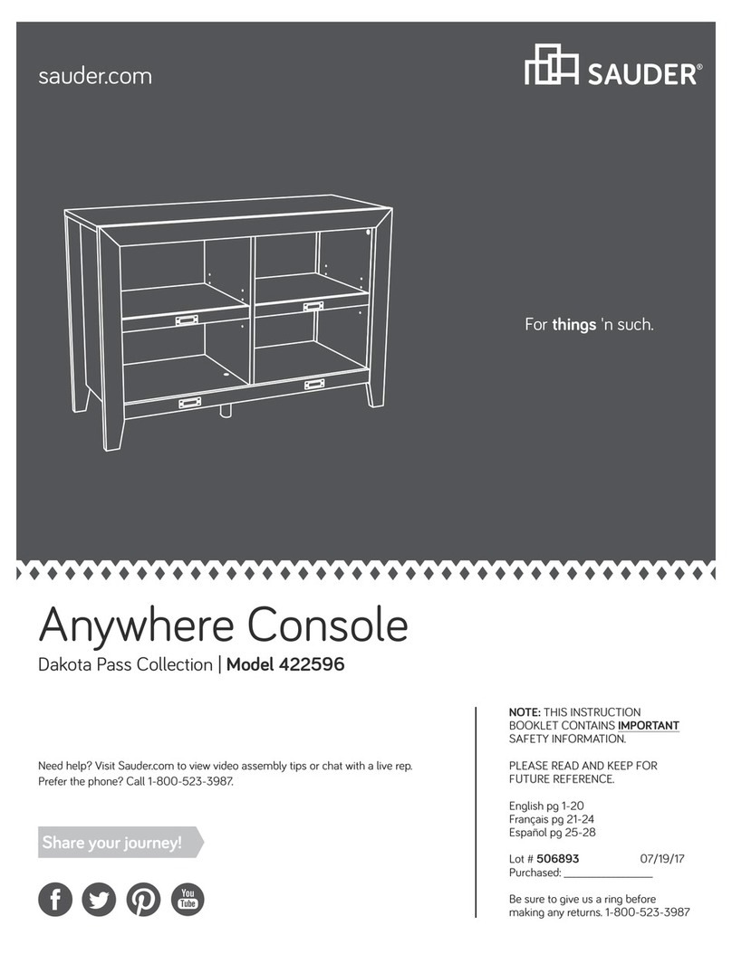
Panel TV Stand
Edge Water Collection | Model 409047
Need help? Visit Sauder.com to view video assembly tips or chat with a live rep.
Prefer the phone? Call 1-800-523-3987.
Share your journey!
sauder.com
Your holder for all
things awesome.
Table of Contents Assembly Tools Required
3
4-5
6-22
23-25
26-28
29-30
31
Part Identification
Hardware Identification
Assembly Steps
Français
Español
Safety
Warranty
Hammer
Not actual size
No. 2 Phillips Screwdriver
Tip Shown Actual Size
Use of a TV that is too heavy or large is hazardous. A TV that is too heavy will create a risk of a tip-over that can cause severe injury or
death. A TV that is too large for the available space might be accidentally pushed or bumped o the furniture, or subject to tip-over.
• Check the size and weight of your TV. Compare it to the diagram below – before you begin assembly!
• This Sauder unit is designed for use with televisions weighing less than 70 pounds. Never use with a TV that weighs more.
• The size of the television, front-to-back and side-to-side, must fit within the space defined in the diagram.
• Never place the front edge of the TV past the front edge of the TV support shelf (or stop molding – if equipped)
• Never allow the sides of the TV to extend past the side edges of the TV support surface.
• If the TV has a CRT picture tube, the picture tube cone may extend past the rear of the support shelf.
• Be sure to apply the warning label as instructed in the last assembly step. The label provides important safety related information.
WARNING
!
70 lbs.
70 lbs.
15-1/8"
15-1/8"
44-1/4"
44-1/4"
409047 www.sauder.com/servicesPage 2
Part Identification
åWhile not all parts are labeled, some of the parts will have a label or an inked letter on the edge
to help distinguish similar parts from each other. Use this part identification to help identify similar parts.
A RIGHT END (1)
B LEFT END (1)
C UPRIGHT (1)
D TOP (1)
E2 BOTTOM (1)
F BACK (1)
G DOOR (2)
H ADJUSTABLE SHELF (2)
I2 LEG (2)
J SKIRT (1)
K2 RIGHT DRAWER FRONT (1)
L2 LEFT DRAWER FRONT (1)
Q STOP MOLDING (1)
R FOOT (2)
S CENTER FOOT (2)
D24 RIGHT DRAWER SIDE (2)
D25 LEFT DRAWER SIDE (2)
D69 DRAWER BACK (2)
D968 DRAWER BOTTOM (2)
409047www.sauder.com/services Page 3
A
B
C
D
E2
F
G
H
I2
J
K2
L2
Q
R
S
H
S
I2
R
G
D24
D25
D968
D69
D24
D25
D968
D69
Hardware Identification
åYou may receive extra hardware with your unit.
35DA CABINET RIGHT - 2 35DD DRAWER LEFT - 2
35DC DRAWER RIGHT - 2
35DB CABINET LEFT - 2
HIDDEN CAM - 8
1F
CAM SCREW - 8
8F
7F TWIST-LOCK®
FASTENER - 10 METAL BRACKET - 5
49G
RUBBER SLEEVE - 8
2R
METAL PIN - 8
1R
KNOB - 6
17K BACKPLATE - 2
18K
CAM COVER - 2
12P
FELT DISC CARD - 1
1M
10A SLIDE CAM - 4
(Refer to Step 12 for proper
location and application)
WARNING LABEL - 1
2L
WARNING
Never use this furniture with a TV that is too
large or too heavy. Severe injury or death
can occur.The TV and furniture will be
unstable and may tip.
-The TV must less than 70 lbs.
-The base of the TV must be able to sit
completely on this shelf.
-Refer to instruction book for complete
safety information.
Note: This is a permanent label. Do not try
to remove. Surface will be damaged.
02/ 02 269224
6E FOOT BRACKET - 1
5E CORNER CAP - 1
409047 www.sauder.com/servicesPage 4
NAIL - 33
1N
14H HINGE - 4
409047www.sauder.com/services Page 5
Hardware Identification
åScrews are shown actual size. You may receive extra hardware with your unit.
BLACK 1-1/8" MACHINE SCREW - 2
21S
BLACK 7/8" MACHINE SCREW - 4
37S
BLACK 9/16" LARGE HEAD SCREW -15
1S
BLACK 1/2" FLAT HEAD SCREW - 8
11S
3S GOLD 5/16" FLAT HEAD SCREW - 16
30S BLACK 1-9/16" FLAT HEAD SCREW - 10
16S BLACK 1-7/8" PAN HEAD SCREW - 2
Step 1 Look for this icon. It means a
video assembly tip is available at
www.sauder.com/services/tips
å Assemble your unit on a carpeted floor or on the empty
carton to avoid scratching your unit or the floor.
å To begin assembly, push a SAUDER TWIST-LOCK®
FASTENER (7F) into the large holes in the RIGHT END (A)
and LEFT END (B).
å Repeat this step for the UPRIGHT (C) and BOTTOM (E2).
409047 www.sauder.com/servicesPage 6
A
B
(10 used)
7F
Do not tighten the TWIST-LOCK® FASTENERS in this step.
Scan this QR code or go to this address:
http://qr.sauder.com/?ID=1341
to watch a video on how to assemble your unit.
å Push eight HIDDEN CAMS (1F) into the large holes in the
ENDS (A and B) and TOP (D).
Step 2
409047www.sauder.com/services Page 7
A
B
D
Arrow
Arrow
1F
The arrow in the HIDDEN
CAM must point toward the
hole in the edge of the board.
Hole
1F
Arrow
(8 used)
Step 3
å Turn eight CAM SCREWS (8F) into the LEGS (I2) and
STOP MOLDING (Q).
409047 www.sauder.com/servicesPage 8
8F
8F
I2
Q
I2
Remember:
Righty tighty.
Lefty loosey.
å Fasten the LEGS (I2) to the ENDS (A and B). Tighten four
HIDDEN CAMS.
å Fasten the STOP MOLDING (Q) to the TOP (D). Tighten
four HIDDEN CAMS.
Step 4
409047www.sauder.com/services Page 9
1
2
A
B
D
I2 Q
I2
Surface with
HIDDEN CAMS
Surface with
HIDDEN CAMS
Surface with
HIDDEN CAMS
These surfaces
should be even.
These surfaces
should be even.
Unfinished surface
Step 5
å Fasten the CABINET RIGHTS (35DA) and CABINET
LEFTS (35DB) to the ENDS (A and B) and UPRIGHT
(C). Use eight GOLD 5/16" FLAT HEAD SCREWS (3S)
through holes #1 and #3.
409047 www.sauder.com/servicesPage 10
A
B
C
I2
I2
Surface with
TWIST-LOCK®
FASTENERS
Surface with
HIDDEN CAMS
Surface with
HIDDEN CAMS
35DA
35DA
35DB
35DB
GOLD 5/16" FLAT HEAD SCREW
(8 used in this step)
3S
Roller end
Roller end
Roller end
1
3
2
1
3
2
35DB
35DB
35DA
35DA
1
3
2
1
Finished edge
å Fasten the LEFT END (B) and UPRIGHT (C) to the
TOP (D). Tighten four TWIST-LOCK® FASTENERS.
Step 6
409047www.sauder.com/services Page 11
Dowel end
How to use the SAUDER TWIST-LOCK®FASTENER
1. Insert the dowel end of the FASTENER into the hole of the
adjoining part.
NOTE: The dowel end of the FASTENER must remain fully
inserted in the hole of the adjoining part while locking
the FASTENER.
2. Tighten the FASTENER with a Phillips screwdriver as tight
as possible.
Surface with HIDDEN CAMS
Surface with
TWIST-LOCK®
FASTENERS
Surface with
TWIST-LOCK®
FASTENERS
B
D
I2
Q
C
Finished edge
Do not stand the unit upright without the
BACK fastened. The unit may collapse.
Caution
Step 7
å Fasten the BOTTOM (E2) to the LEFT END (B). Tighten
two TWIST-LOCK® FASTENERS.
å Fasten the BOTTOM (E2) to the UPRIGHT (C). Use two
BLACK 1-9/16" FLAT HEAD SCREWS (30S).
409047 www.sauder.com/servicesPage 12
Surface with
TWIST-LOCK®
FASTENERS
These holes must be here.
B
C
E2
Don't worry. It isn't
Rome. This can be built
in a day.
BLACK 1-9/16" FLAT HEAD SCREW
(2 used in this step)
30S
å Fasten the RIGHT END (A) to the TOP (D) and BOTTOM (E2).
Tighten four TWIST-LOCK® FASTENERS.
å Fasten the FEET (R) to the LEGS (I2). Use two BLACK 1-7/8" PAN
HEAD SCREWS (16S).
å Fasten five METAL BRACKETS (49G) to the BOTTOM (E2). Use
five BLACK 9/16" LARGE HEAD SCREWS (1S).
å Fasten the SKIRT (J) to the METAL BRACKETS (49G). Use five
BLACK 9/16" LARGE HEAD SCREWS (1S) through the BRACKETS
and into the SKIRT.
Step 8
409047www.sauder.com/services Page 13
R
R
I2
A
I2
Surface without
TWIST-LOCK®
FASTENERS
D
BLACK 9/16" LARGE HEAD SCREW
(10 used for the METAL BRACKETS)
1S
49G
J
E2
Finished surface
Curved edge
BLACK 1-7/8" PAN HEAD SCREW
(2 used for the FEET)
16S
Step 9
å Fasten the FOOT BRACKET (6E) to the BOTTOM (E2). Use
three BLACK 9/16" LARGE HEAD SCREWS (1S).
å Slide the CENTER FEET (S) onto the FOOT BRACKET (6E).
å Slide the FOOT CAP (5E) onto the CENTER FEET (S).
409047 www.sauder.com/servicesPage 14
BLACK 9/16" LARGE HEAD SCREW
(3 used for the FOOT BRACKET)
1S
S
S
6E
5E
E2
å Carefully turn your unit over onto its front edges. Unfold the
BACK (F) and lay it over your unit.
å Make equal margins along all four edges of the BACK (F). Push
on opposite corners of your unit if needed to make it "square".
å Fasten the BACK (F) to your unit using the NAILS (1N).
å NOTE: Be sure to tap NAILS into the holes that line up over
the UPRIGHT (C).
å NOTE: Perforations have been provided for access through the
BACK. Carefully cut out the holes needed.
å Turn two BLACK 9/16" LARGE HEAD SCREWS (1S) into the short
slots of the FOOT BRACKET (6E).
Step 10
409047www.sauder.com/services Page 15
These holes must line up
over the UPRIGHT (C).
NAIL
(33 used for the BACK)
1N
BLACK 9/16" LARGE HEAD SCREW
(2 used for the FOOT BRACKET)
1S
F
6E
Do not stand the unit upright without the
BACK fastened. The unit may collapse.
Caution
Step 11
å Fasten two HINGES (14H) to each DOOR (G). Use eight
BLACK 1/2" FLAT HEAD SCREWS (11S).
409047 www.sauder.com/servicesPage 16
BLACK 1/2" FLAT HEAD SCREW
(8 used in this step)
11S
G
G
14H
14H
å Carefully stand your unit upright.
å Before fastening the DOOR to your unit, be sure the mounting screw is against the stops as shown in the
diagram. If it isn't, loosen the mounting screw to slide it against the stops. Then, tighten the mounting screw.
å Fasten a DOOR (G) to the LEFT END (B). Use the screws in the HINGES. See the next step for adjustments.
å Fasten a BACKPLATE (18K) and KNOB (17K) to the DOOR (G). Use a BLACK 1-1/8" MACHINE SCREW (21S).
å Peel the FELT DISC from the FELT DISC CARD (1M). Stick a FELT DISC on the DOOR where it comes in contact
with the UPRIGHT (C).
å Repeat this step for the other door.
å Apply the WARNING LABEL (2L ) to the TOP (D). You should be able to read the label when the TV is removed
from the unit. When the TV is in place, it should hide the label. Peel o the backing and apply the label as shown
in the diagram.
å NOTE: This is a permanent label intended to last for the life of the product. Once applied, do not try to remove it.
Step 12
409047www.sauder.com/services Page 17
2L
WARNING
Never use this furniture with a TV that is too
large or too heavy. Severe injury or death can
occur. The TV and furniture will be unstable
and may tip.
- The TV must weigh less than 70 lbs.
- The base of the TV must be able to sit
completely on this shelf.
D
C
B
G
17K 18K
1M
BLACK 1-1/8" MACHINE SCREW
(2 used in this step)
21S
Mounting
screw
Stop
Hinge
Step 13
409047 www.sauder.com/servicesPage 18
å Refer to the enlarged diagram to identify the parts on the HINGES.
å The DOORS may need some adjustments. Follow the text below to
make needed adjustments.
å DOOR ADJUSTMENTS:
To adjust the DOORS from side to side (horizontal), turn the
adjusting screw in or out.
å To adjust the DOORS up and down (vertical), loosen both vertical
adjustment screws. Move the DOORS up or down to the desired
location. Tighten the screws after making adjustments.
å To adjust the DOORS in or out (depth), loosen the mounting screw
one turn and move the DOORS in or out, as needed. Tighten the
mounting screw after making adjustments.
Adjusting screw (horizontal)
Mounting screw (depth)
(vertical adjustment)
Step 14
409047www.sauder.com/services Page 19
VIEW THE T-LOCK BOX VIDEO
å Fasten the DRAWER BACK (D69) to the DRAWER SIDES (D24
and D25). Use four BLACK 1-9/16" FLAT HEAD SCREWS (30S).
å NOTE: Be sure the DRAWER BOTTOM (D968) inserts into the
groove of the DRAWER BACK (D69).
å Repeat this step for the other drawer.
12
3
å Insert the DRAWER SIDES (D24 and D25) at
an angle into the slot at each end of the LEFT
DRAWER FRONT (L2).
å Slide the DRAWER BOTTOM (D968) into the
grooves in the DRAWER SIDES (D24 and D25) and
LEFT DRAWER FRONT (L2).
The tabs should insert freely
into the slots. Gently tilt the
DRAWER SIDES side to side
until the tabs slip into the slots.
Groove Be sure the DRAWER
BOTTOM inserts into the
DRAWER FRONT groove.
D24
D25
D968
D968
D24
D25
D69
D25
L2 L2
Unfinished
surface
With the palm of your hand,
tap the DRAWER BOTTOM
down into the groove.
D24
Start each screw a few turns before
completely tightening any of them.
BLACK 1-9/16" FLAT HEAD SCREW
(8 used in this step)
30S
Step 15
å Insert a SLIDE CAM (10A) into each DRAWER SIDE (D24 and
D25).
å Fasten the DRAWER RIGHT (35DC) and DRAWER LEFT (35DD)
to the DRAWER SIDES (D24 and D25). Use four GOLD 5/16"
FLAT HEAD SCREWS (3S).
å NOTE: The screw head in the CAM must be visible through the
slotted hole in the SLIDE.
å Fasten two KNOBS (17K) to the LEFT DRAWER FRONT (L2). Use
two BLACK 7/8" MACHINE SCREWS (37S).
å Repeat this step for the other drawer.
409047 www.sauder.com/servicesPage 20
BLACK 7/8" MACHINE SCREW
(4 used for the KNOBS)
37S
35DD
35DD
35DC
35DC
1
32
1
32
Roller end
Roller end
17K
Screw head - turn CAM to line up holes in
the SLIDES with holes in DRAWER SIDES
10A
10A
L2
D24
D25
Almost time to
celebrate! With a nap.
GOLD 5/16" FLAT HEAD SCREW
(8 used for the SLIDES)
3S
(4 screws per drawer)

Other Sauder Indoor Furnishing manuals
Sauder Shoal Creek 417678 User manual

Sauder

Sauder Shoal Creek 417678 User manual

Sauder Harbor View 401685 User manual

Sauder

Sauder Harbor View 401685 User manual

Sauder 410367 User manual

Sauder

Sauder 410367 User manual

Sauder 422197 User manual

Sauder

Sauder 422197 User manual

Sauder Costa 419961 User manual

Sauder

Sauder Costa 419961 User manual

Sauder Pinwheel 421888 User manual

Sauder

Sauder Pinwheel 421888 User manual
Sauder 421952 User manual

Sauder

Sauder 421952 User manual

Sauder North Avenue 422097 User manual

Sauder

Sauder North Avenue 422097 User manual

Sauder Radial 426023 User manual

Sauder

Sauder Radial 426023 User manual

Sauder Englewood 426909 User manual

Sauder

Sauder Englewood 426909 User manual

Sauder 414720 User manual

Sauder

Sauder 414720 User manual

Sauder 426932 User manual

Sauder

Sauder 426932 User manual

Sauder 401804 User manual

Sauder

Sauder 401804 User manual

Sauder Steel River 427855 User manual

Sauder

Sauder Steel River 427855 User manual

Sauder New Grange 420021 User manual

Sauder

Sauder New Grange 420021 User manual

Sauder Steel River 427549 User manual

Sauder

Sauder Steel River 427549 User manual

Sauder Costa 419958 User manual

Sauder

Sauder Costa 419958 User manual

Sauder North Avenue 424933 User manual

Sauder

Sauder North Avenue 424933 User manual

Sauder Cannery Bridge 429515 User manual

Sauder

Sauder Cannery Bridge 429515 User manual

Sauder Costa Credenza 422984 User manual

Sauder

Sauder Costa Credenza 422984 User manual

Sauder Edge Water 408696 User manual

Sauder

Sauder Edge Water 408696 User manual

Sauder Via 419613 User manual

Sauder

Sauder Via 419613 User manual

Sauder Lateral File Pacific View 427360 User manual

Sauder

Sauder Lateral File Pacific View 427360 User manual

Sauder Heritage Hill Lateral File 102702 User manual

Sauder

Sauder Heritage Hill Lateral File 102702 User manual

Popular Indoor Furnishing manuals by other brands

PHI VILLA THD5-096B-112 Use and care guide

PHI VILLA

PHI VILLA THD5-096B-112 Use and care guide

Gami 273 manual

Gami

Gami 273 manual

RTA CLR3114 Assembly instructions

RTA

RTA CLR3114 Assembly instructions

TUHOME Furniture MAGNUM BLA3976 Assembly instructions

TUHOME Furniture

TUHOME Furniture MAGNUM BLA3976 Assembly instructions

World Market 585015 Assembly instructions

World Market

World Market 585015 Assembly instructions

Furniture of America FGI-2085C31 Assembly instructions

Furniture of America

Furniture of America FGI-2085C31 Assembly instructions

2K FURNITURE DESIGN D513 Assembly instructions

2K FURNITURE DESIGN

2K FURNITURE DESIGN D513 Assembly instructions

BOX15 411/39.1130.25 F Assembly instructions

BOX15

BOX15 411/39.1130.25 F Assembly instructions

BLACK RED WHITE S320-LOZ90x200 Assembly

BLACK RED WHITE

BLACK RED WHITE S320-LOZ90x200 Assembly

pottery barn kids PRESTON ART CONSOLE manual

pottery barn kids

pottery barn kids PRESTON ART CONSOLE manual

DURAVIT LM 7849 Mounting instructions

DURAVIT

DURAVIT LM 7849 Mounting instructions

Amart Furniture ARAGON Assembly instruction

Amart Furniture

Amart Furniture ARAGON Assembly instruction

fantastic furniture Tivoli Sofa 1 Seater quick start guide

fantastic furniture

fantastic furniture Tivoli Sofa 1 Seater quick start guide

BLACK RED WHITE B169-KOM4D2S Assembly

BLACK RED WHITE

BLACK RED WHITE B169-KOM4D2S Assembly

cinetto PS40.3 Assembly instructions

cinetto

cinetto PS40.3 Assembly instructions

Argos Home Hygena 4158714 Assembly instructions

Argos Home

Argos Home Hygena 4158714 Assembly instructions

evodesk PRO Assembly & operation manual

evodesk

evodesk PRO Assembly & operation manual

Whittier Wood Furniture McKenzie 1550b Assembly instructions

Whittier Wood Furniture

Whittier Wood Furniture McKenzie 1550b Assembly instructions

manuals.online logo
manuals.online logoBrands
  • About & Mission
  • Contact us
  • Privacy Policy
  • Terms and Conditions

Copyright 2025 Manuals.Online. All Rights Reserved.