manuals.online logo
Brands
  1. Home
  2. •
  3. Brands
  4. •
  5. Sauder
  6. •
  7. Indoor Furnishing
  8. •
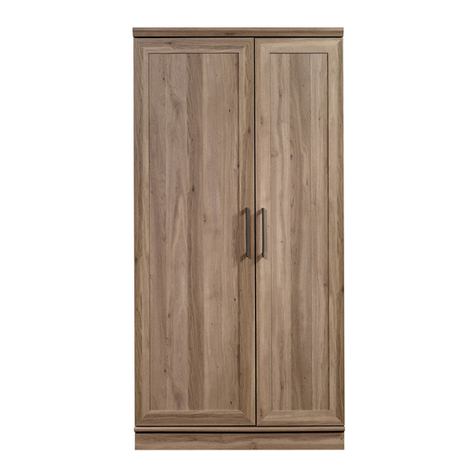
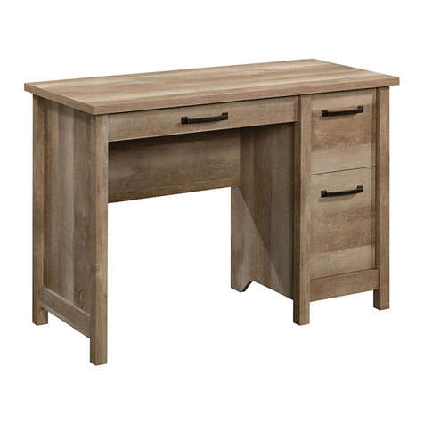
  9. Sauder Carson Forge 412920 User manual

Sauder Carson Forge 412920 User manual

Share your journey!
NOTE: THIS INSTRUCTION
BOOKLET CONTAINS IMPORTANT
SAFETY INFORMATION.
PLEASE READ AND KEEP FOR
FUTURE REFERENCE.
English pg 1-34
Français pg 35-39
Español pg 40-44
Lot # 547518 08/18/20
Purchased: __________________
Desk
Carson Forge Collection | Model
WARNING
CHOKING HAZARD - Small Parts
Not for children under 3 years.
Adult assembly required.
Table of Contents Assembly Tools Required
Part Identification
Hardware Identification
Assembly Steps
Français
Español
Safety
Warranty
No. 2 Phillips Screwdriver
Tip Shown Actual Size
Hammer
Not actual size
A RIGHT END (1)
B UPPER LEFT END (1)
B59 LARGE DRAWER BOTTOM (1)
C LOWER LEFT END (1)
D UPRIGHT (1)
D36 RIGHT DRAWER SIDE (1)
D37 LEFT DRAWER SIDE (1)
D48 FILE RIGHT DRAWER SIDE (1)
D49 FILE LEFT DRAWER SIDE (1)
D77 DRAWER BACK (1)
D78 FILE DRAWER BACK (1)
D113 PENCIL DRAWER SIDE (2)
D574
PENCIL DRAWER BOX FRONT (2)
D716 SMALL DRAWER BOTTOM (2)
E2 TOP (1)
F BOTTOM (1)
G MODESTY PANEL (1)
H BACK (1)
I BRACE (1)
J DRAWER FRONT (1)
M71
DRAWER BRACE (1)
(Hidden part using recycled
material. Color may vary.)
M75 END MOLDING (1)
N FILE DRAWER FRONT (1)
R3 PENCIL DRAWER FRONT (1)
U RIGHT FRONT LEG (1)
V LEFT FRONT LEG (1)
W RIGHT REAR LEG (1)
X LEFT REAR LEG (1)
Y CENTER LEG (1)
Z EXTENSION BLOCK (1)
2-3
4-5
6-34
35-39
40-44
45-46
47
åWhile not all parts are labeled, some of the parts will have a label or an inked letter on the edge
to help distinguish similar parts from each other. Use this part identification to help identify similar parts.
Now you know
our ABCs.
Part Identification
Page 2
Scissors
Masking Tape
Part Identification
Page 3
A
B
C
D
E2
F
G
H
U
W
X
V
I
Z
M75
Y
N
D78 D48
D716
D49
J
D36
D77
D716
D37
D574
B59
R3
M71
D574
D113
D113
Hardware Identification
åScrews are shown actual size. You may receive extra hardware with your unit.
Page 4
40CB CABINET LEFT - 3
40CA CABINET RIGHT - 3 40CC DRAWER RIGHT - 3 40CD DRAWER LEFT - 3
TACK GLIDE - 5
12E
FOOT - 5
10E
CORNER ACCENT - 3
8E HIDDEN CAM - 23
1F
FILE GLIDE - 2
4B
WOOD DOWEL - 9
15F
CAM DOWEL - 10
2F CAM SCREW -13
8F DRAWER FRONT
BRACKET - 1
9G
FILE DRAWER
FRONT BRACKET - 2
10G PULL - 2
53K52K KNOB SET - 2 METAL BRACE - 1
159M
CAM COVER - 4
12P
CORD CLIP - 2
4P
NAIL - 20
1N
GLUE - 1
177M
Hardware Identification
åScrews are shown actual size. You may receive extra hardware with your unit.
Page 5
30S BLACK 1-9/16" FLAT HEAD SCREW - 18 BLACK 9/16" FLAT HEAD SCREW - 2
32S
BLACK 7/8" MACHINE SCREW - 2
37S SILVER 1/2" MACHINE SCREW - 5
38S
BROWN 9/16" LARGE HEAD SCREW - 12
40S SILVER 2" FLAT HEAD SCREW - 4
57S
SILVER 1-1/8" FLAT HEAD SCREW - 2
10S3S GOLD 5/16" FLAT HEAD SCREW - 24
HIDDEN WIRELESS Qi COMPATIBLE CHARGER by
EGGTRONIC - Item 425905 (sold separately)
p
o
w
e
r
e
d
b
y
E
G
G
T
R
O
N
I
C
p
o
w
e
r
e
d
b
y
E
G
G
T
R
O
N
I
C
p
o
w
e
r
e
d
b
y
E
G
G
T
R
O
N
I
C
p
o
w
e
r
e
d
b
y
E
G
G
T
R
O
N
I
C
SILVER 1-1/2" MACHINE SCREW - 2
95S
BLACK 2-1/4" FLAT HEAD SCREW - 3
26S
BLACK 7/8" LARGE HEAD SCREW - 3
17S
Step 1 Look for this icon. It means a
video assembly tip is available at
www.sauder.com/services/tips
å Assemble your unit on a carpeted floor or on the empty
carton to avoid scratching your unit or the floor.
å Push ten HIDDEN CAMS (1F) into the RIGHT END (A),
UPRIGHT (D), BOTTOM (F), and BRACE (I). Then, insert the
metal end of a CAM DOWEL (2F) into each HIDDEN CAM.
I
A
D
F
(10 used)
Arrow
1F
2F
Insert the metal end of the CAM
DOWEL into the HIDDEN CAM.
Arrow
Do not tighten the HIDDEN CAMS in this step.
Page 6
Step 2
I
C
A
D
G
å Push thirteen HIDDEN CAMS (1F) into the holes in the
ENDS (A and C), UPRIGHT (D), MODESTY PANEL (G),
and BRACE (I).
1F
Arrow
Arrow
1F
Arrow
1F
(13 used)
Arrow
The arrow in the HIDDEN
CAM must point toward the
hole in the edge of the board.
Hole
Page 7
Step 3
Page 8
8F
å Turn thirteen CAM SCREWS (8F) into the LEGS (U, V, X, and Y).
å NOTE: Be sure to use the exact holes shown.
Y
U
V
X
8F
(13 used)
Remember:
Righty tighty.
Lefty loosey.
Page 9
å Fasten the CORNER ACCENTS (8E) to the LEGS (U, V, and Y).
Use two BLACK 7/8" MACHINE SCREWS (37S) through the
LEGS (U and Y). Use one SILVER 1/2" MACHINE SCREW (38S)
through the LEFT FRONT LEG (V).
Step 4
V
Y
U
8E
8E
BLACK 7/8" MACHINE SCREW
(2 used in this step)
37S
Angled edge
8E
SILVER 1/2" MACHINE SCREW
(1 used in this step)
38S
Step 5
Page 10
A
åTurn two BLACK 9/16" FLAT HEAD SCREWS (32S) into
the RIGHT END (A) until the shoulders of the SCREWS
rest on the surface of the END.
åNOTE: Do not overtighten the SCREWS.
åSlide the END MOLDING (M75) onto the END (A). Line
up the groove in the MOLDING over the heads of the
SCREWS in the END.
åNOTE: The MOLDING should be even on both edges of
the END.
åNOTE: If the MOLDING comes up o of the SCREWS,
remove it and slide it on again.
BLACK 9/16" FLAT HEAD SCREW
(2 used in this step)
32S
Shoulder
Apply pressure with your hands
as you guide the MOLDING over
the SCREWS and onto the END.
Surface without
HIDDEN CAMS
M75
å Fasten the END (A) to the RIGHT FRONT LEG (U) as
shown in the right diagram. Tighten three HIDDEN CAMS.
å Fasten the RIGHT REAR LEG (W) to the RIGHT END (A).
Use three BLACK 2-1/4" FLAT HEAD SCREWS (26S).
å Fasten the UPRIGHT (D) to the CENTER LEG (Y) as shown
in the left diagram. Tighten three HIDDEN CAMS.
Step 6
Page 11
U
A
Angled edge
Surface with
HIDDEN CAMS
W
Angled edge
The LEGS will overhang
this edge of the END.
D
Y
Surface with
HIDDEN CAMS
Angled edge
The LEG will overhang
this edge of the END.
BLACK 2-1/4" FLAT HEAD SCREW
(3 used in this step)
26S
12
Step 7
å First, fill the holes in one edge of the UPPER LEFT END (B) 1/4
to 1/2 full with GLUE (177M). Then, insert the WOOD
DOWELS (15F) into the holes. Wipe away the excess GLUE.
å Repeat adding GLUE and inserting the WOOD DOWELS in
the short edges of the LOWER LEFT END (C) and BRACE (I)
as shown below.
å Now, fasten the BRACE (I) to UPPER LEFT END (B). Use two
SILVER 1-1/8" FLAT HEAD SCREWS (10S).
Surface with
HIDDEN CAMS
I
Surface with
HIDDEN CAMS
Surface with holes
C
B
15F
15F
Edge with HIDDEN CAMS
The holes should be
closer to this edge.
SILVER 1-1/8" FLAT HEAD SCREW
(2 used in this step)
10S
Page 12
Inspect the parts thoroughly before
assembling. Disassembly of glued
parts is extremely dicult.
Caution
!
177M
Fill the holes 1/4 to 1/2 full with GLUE.
Step 8
å First, fill the four holes in the edge of the LEFT REAR LEG (X)
1/4 to 1/2 full with GLUE (177M). Then, insert the WOOD
DOWELS in the ENDS (B and C) and BRACE (I) into the holes of
the LEG. Wipe away the excess GLUE.
å NOTE: Be sure the CAM SCREWS insert into the holes in the
short edges of the LOWER LEFT END (C) and BRACE (I).
å Fasten the LEFT REAR LEG (X) to the LOWER LEFT END (C)
and BRACE (I). Tighten two HIDDEN CAMS.
å Repeat this step for the LEFT FRONT LEG (V) making sure all
HIDDEN CAMS are tight.
Surface with
HIDDEN CAMS
Surface with
HIDDEN CAMS
V
I
C
B
X
Angled edge
Angled edge
Page 13
Inspect the parts thoroughly before
assembling. Disassembly of glued
parts is extremely dicult.
Caution
!
177M
Fill the holes 1/4 to 1/2 full with GLUE.
Step 9
å Fasten two CABINET RIGHTS (40CA) to the RIGHT
END (A) and two CABINET LEFTS (40CB) to the
UPRIGHT (D). Use eight GOLD 5/16" FLAT HEAD
SCREWS (3S) through holes #1 and #3.
1
2
3
4
1
2
34
A
D
Roller end
Roller end
Angled edge
1
2
34
1
2
3
4
Surface with
HIDDEN CAMS
Surface with
HIDDEN CAMS
Page 14
GOLD 5/16" FLAT HEAD SCREW
(8 used in this step)
3S
These holes must be here.
å Carefully flip the UPRIGHT (D) over.
å Fasten the EXTENSION BLOCK (Z) to the UPRIGHT (D).
Use two SILVER 2" FLAT HEAD SCREWS (57S).
å Fasten one CABINET RIGHT (40CA) to the EXTENSION
BLOCK (Z) and one CABINET LEFT (40CB) to the
BRACE (I). Use four GOLD 5/16" FLAT HEAD
SCREWS (3S) through holes #1 and #3.
Step 10
Z
D
I
Angled edge
Roller end
1
2
3
4
1
2
34
SILVER 2" FLAT HEAD SCREW
(2 used for the EXTENSION BLOCK)
57S
Finished
surface
Page 15
GOLD 5/16" FLAT HEAD SCREW
(4 used in this step)
3S
Roller end
Surface without
HIDDEN CAMS
The CAM SCREWS
must be here.
åInsert a WOOD DOWEL (15F) into the hole in the TOP (E2).
åFasten the BRACE (I) to the TOP (E2). Tighten two
HIDDEN CAMS.
åNOTE: Be sure the WOOD DOWEL in the TOP inserts
into the hole in the LEG.
åFasten the MODESTY PANEL (G) to the LEFT REAR
LEG (X). Tighten three HIDDEN CAMS.
Step 11
Surface with holes
X
G
E2
I
15F
Surface with
HIDDEN CAMS
Curved edge
Start Tighten
Arrow
Minimum
190 degrees
Caution
Risk of damage or
injury. HIDDEN CAMS
must be completely
tightened. HIDDEN
CAMS that are not
completely tightened
may loosen, and parts
may separate. To
completely tighten:
Arrow
Maximum
210 degrees
Do not stand the unit upright without the
BACK fastened. The unit may collapse.
Caution
Page 16
å Fasten the UPRIGHT (D) to the TOP (E2). Tighten two
HIDDEN CAMS.
å Fasten the UPRIGHT (D) to the MODESTY PANEL (G).
Use two SILVER 2" FLAT HEAD SCREWS (57S).
å Fasten the METAL BRACE (159M) to the LEFT
LEGS (V and X). Use four BROWN 9/16" LARGE
HEAD SCREWS (40S).
Step 12
D
G
E2
V
X
Arrow
Minimum
190 degrees
Maximum
210 degrees
SILVER 2" FLAT HEAD SCREW
(2 used in this step)
57S
Surface with
HIDDEN CAMS
Page 17
159M
BROWN 9/16" LARGE HEAD SCREW
(4 used for the METAL BRACE)
40S
å This piece of furniture accommodates an optional Hidden Wireless Qi Compatible
Charger by Eggtronic (Item 425905) for charging your smart phone. Eliminate the
clutter and inconvenience of a charging cable. Charge your phone by simply setting it
on top of your furniture.
Qi Compatible Approved Smartphone List
The embedded wireless charging system is designed for the following smartphones:
• Apple (iPhone 8 or newer)
• Samsung (Galaxy 6 or newer)
• For a complete compatibility list, go to sauder.com.
Wirelessly charge
your phone by setting
it on top of your
furniture here.
Page 18
Step 13 Optional Hidden Wireless Qi Compatible Charger by Eggtronic (sold separately)
å If you did not purchase the optional Hidden Wireless Qi Compatible
Charger by Eggtronic go to the next step.
å Push two CORD CLIPS (4P) into the holes in the TOP (E2).
åNOTE: The CORD CLIP is used to hold your HIDDEN WIRELESS
CHARGER cord.
åInsert the HIDDEN WIRELESS Qi COMPATIBLE CHARGER by
EGGTRONIC into the large hole in the TOP (E2).
åUse the two SCREWS included with the CHARGER to secure it into
the TOP (E2).
åNOTE: There are no pre-drilled holes in the hole in the TOP for the
CHARGER. The sides of the CHARGER will expand into the sides of
the large hole as you tighten the SCREWS.
WARNING
Please use the wireless charging port
correctly and safely. Improper use can
cause safety hazards, or damage to your
furniture or household items. Carefully
read the following safety information.
• AVOID dropping
• NEVER use in or near water
• DO NOT disassemble
• DO NOT expose to liquids
• DO NOT use with an extension cord
For safest and fastest charge, only use
original or certified cables.
E2
4P
Page 19
Step 14 Optional Hidden Wireless Qi Compatible Charger by Eggtronic (sold separately)
This device complies with part 15 of the FCC Rules. Operation is subject to the following two conditions: (1) This device may not cause harmful
interference, and (2) this device must accept any interference received, including interference that may cause undesired operation.
"Changes or modifications not expressly approved by the party responsible for compliance could void the user's authority to operate this device".
OR
"Changes or modifications not expressly approved by Sauder Woodworking Co. could void the user's authority to operate this device".
NOTE: This equipment has been tested and found to comply with the limits for a Class B digital device, pursuant to part 15 of the FCC Rules.
These limits are designed to provide reasonable protection against harmful interference in a residential installation. This equipment generates,
uses, and can radiate radio frequency energy and, if not installed and used in accordance with the instructions, may cause harmful interference
to radio communications. However, there is no guarantee that interference will not occur in a particular installation. If this equipment does
cause harmful interference to radio or television reception, which can be determined by turning the equipment o and on, the user is
encouraged to try to correct the interference by one or more of the following measures:
-Reorient or relocate the receiving antenna.
-Increase the separation between the equipment and receiver.
-Connect the equipment into an outlet on a circuit dierent from that to which the receiver is connected.
-Consult the dealer or an experienced radio/TV technician for help.
The sides of the CHARGER will
expand into the sides of the large
hole as you tighten the SCREWS.
å Fasten the BOTTOM (F) to the UPRIGHT (D). Tighten
two HIDDEN CAMS.
å Fasten the RIGHT END (A) to the TOP (E2) and
BOTTOM (F). Tighten four HIDDEN CAMS.
Step 15
Arrow
Minimum
190 degrees
Maximum
210 degrees
D
E2
F
A
Surface with
HIDDEN CAMS
Page 20
Surface without
HIDDEN CAMS
Unfinished edge

Other manuals for Carson Forge 412920

1

Other Sauder Indoor Furnishing manuals

Sauder Viabella 420870 User manual

Sauder

Sauder Viabella 420870 User manual

Sauder Via 419708 User manual

Sauder

Sauder Via 419708 User manual
Sauder Orchard Hills 401346 User manual

Sauder

Sauder Orchard Hills 401346 User manual

Sauder Boulevard Cafe 420650 User manual

Sauder

Sauder Boulevard Cafe 420650 User manual

Sauder 415546 User manual

Sauder

Sauder 415546 User manual

Sauder Armoire 419451 User manual

Sauder

Sauder Armoire 419451 User manual

Sauder Via 419609 User manual

Sauder

Sauder Via 419609 User manual

Sauder 413072 User manual

Sauder

Sauder 413072 User manual

Sauder County Line 415996 User manual

Sauder

Sauder County Line 415996 User manual

Sauder 422893 User manual

Sauder

Sauder 422893 User manual

Sauder 423032 User manual

Sauder

Sauder 423032 User manual

Sauder 418269 User manual

Sauder

Sauder 418269 User manual

Sauder 420545 User manual

Sauder

Sauder 420545 User manual

Sauder Shoal Creek 411236 User manual

Sauder

Sauder Shoal Creek 411236 User manual

Sauder August Hill 426133 User manual

Sauder

Sauder August Hill 426133 User manual

Sauder Pinwheel Collection 422600 User manual

Sauder

Sauder Pinwheel Collection 422600 User manual

Sauder 418735 User manual

Sauder

Sauder 418735 User manual

Sauder 419119 User manual

Sauder

Sauder 419119 User manual

Sauder North Avenue 426016 User manual

Sauder

Sauder North Avenue 426016 User manual

Sauder Barrister Lane 422268 User manual

Sauder

Sauder Barrister Lane 422268 User manual

Sauder Cliff ord Place Credenza 429507 User manual

Sauder

Sauder Cliff ord Place Credenza 429507 User manual

Sauder Craft Table 421417 User manual

Sauder

Sauder Craft Table 421417 User manual

Sauder Harbor View 158085 User manual

Sauder

Sauder Harbor View 158085 User manual

Sauder 429430 User manual

Sauder

Sauder 429430 User manual

Popular Indoor Furnishing manuals by other brands

California Closets Martha Stewart Cabinet with Mesh Door installation manual

California Closets

California Closets Martha Stewart Cabinet with Mesh Door installation manual

Salon & Co SC169 owner's manual

Salon & Co

Salon & Co SC169 owner's manual

Ronbow Signature series Installation and care guide

Ronbow

Ronbow Signature series Installation and care guide

LF Portfolio LSTC04MT manual

LF

LF Portfolio LSTC04MT manual

Teak Isle Holy Night Outdoor Nativity Set Assembly instructions

Teak Isle

Teak Isle Holy Night Outdoor Nativity Set Assembly instructions

CAPIEM FURTIF User Instruction with warranty specifications

CAPIEM

CAPIEM FURTIF User Instruction with warranty specifications

PROMART 1138 manual

PROMART

PROMART 1138 manual

IKEA STEFAN Assembly instructions

IKEA

IKEA STEFAN Assembly instructions

Flexispot Comhar Pro Q8 installation guide

Flexispot

Flexispot Comhar Pro Q8 installation guide

KEUCO Royal 15 14405 171301 Instructions for use

KEUCO

KEUCO Royal 15 14405 171301 Instructions for use

Kis SPLIT PREMIUM Assembly instruction

Kis

Kis SPLIT PREMIUM Assembly instruction

Woltra COOL C-09 Assembly instructions

Woltra

Woltra COOL C-09 Assembly instructions

Tutti Bambini COZee XL user guide

Tutti Bambini

Tutti Bambini COZee XL user guide

Runfine RFVA0069B Operator's manual

Runfine

Runfine RFVA0069B Operator's manual

Furniture of America CM3549-T Assembly instructions

Furniture of America

Furniture of America CM3549-T Assembly instructions

Southern Enterprises Kedzie Multilevel Desk HO730400TX Assembly instructions

Southern Enterprises

Southern Enterprises Kedzie Multilevel Desk HO730400TX Assembly instructions

IKEA KOMPLEMENT installation instructions

IKEA

IKEA KOMPLEMENT installation instructions

Rev-A-Shelf 486-30VSBSC-BM-1 quick start guide

Rev-A-Shelf

Rev-A-Shelf 486-30VSBSC-BM-1 quick start guide

manuals.online logo
manuals.online logoBrands
  • About & Mission
  • Contact us
  • Privacy Policy
  • Terms and Conditions

Copyright 2025 Manuals.Online. All Rights Reserved.