manuals.online logo
Brands
  1. Home
  2. •
  3. Brands
  4. •
  5. Sauder
  6. •
  7. Indoor Furnishing
  8. •
  9. Sauder HomePlus 422428 User manual

Sauder HomePlus 422428 User manual

Need help? Visit Sauder.com to view video assembly tips or chat with a live rep.
Prefer the phone? Call 1-800-523-3987.
Share your journey!
Store behind
closed doors.
NOTE: THIS INSTRUCTION
BOOKLET CONTAINS IMPORTANT
SAFETY INFORMATION.
PLEASE READ AND KEEP FOR
FUTURE REFERENCE.
English pg 1-40
Français pg 41-46
Español pg 47-52
Lot # 506191 08/23/17
Purchased: __________________
Be sure to give us a ring before
making any returns. 1-800-523-3987
Storage Cabinet
HomePlus Collection | Model 422428
sauder.com
Table of Contents Assembly Tools Required
Part Identification
Hardware Identification
Assembly Steps
Français
Español
Safety
Warranty
Hammer
Not actual size
No. 2 Phillips Screwdriver
Tip Shown Actual Size
3
4-5
6-40
41-46
47-52
53-54
55
422428 www.sauder.com/servicesPage 2
Electric drill with 1/4" bit
(ONLY in indicated step)
Part Identification Now you know
our ABCs.
A2 SMALL END (1)
B2 LARGE END (1)
C DOOR END (1)
D2 UPRIGHT (1)
E2 TOP (1)
F2 BOTTOM (1)
G DOOR SHELF (3)
H DOOR UPRIGHT (1)
I LARGE SHELF (1)
J SMALL SHELF (1)
K BACK (1)
L2 LARGE DOOR (1)
M SMALL DOOR (1)
N LARGE ADJUSTABLE SHELF (2)
O ADJUSTABLE DOOR SHELF (3)
P SMALL ADJUSTABLE SHELF (2)
Q FRONT SKIRT (1)
R SIDE SKIRT (2)
S TOP MOLDING (1)
422428www.sauder.com/services Page 3
åWhile not all parts are labeled, some of the parts will have a label or an inked letter on the edge
to help distinguish similar parts from each other. Use this part identification to help identify similar parts.
A2
B2
C
D2
E2
F2
G
G
G
H
IJ
K
L2
M
N
N
O
O
O
P
P
Q
R
R
S
102K
åScrews are shown actual size. You may receive extra hardware with your unit.
Hardware Identification
ADJUSTABLE FOOT - 2
25E
ADJUSTABLE GLIDE - 4
18E
PROPEL NUT - 4
14M
HINGE - 4
1H
FOOT BASE - 2
24E
PULL - 2
STRIKE PLATE - 2
6I
422428 www.sauder.com/servicesPage 4
10F TWIST-LOCK®FASTENER - 27
FRONT FOOT - 2
32E
REAR FOOT - 2
31E
METAL BRACKET - 1
4G 13H HINGE - 3
14P HOLE PLUG - 8
NAIL - 72
1N
WASHER - 1
13M
SAFETY DRYWALL
ANCHOR - 1
61M
SAFETY STRAP - 1
60M
Locate this nylon SAFETY
STRAP (60M) to be used
later in assembly. Do not
accidentally throw away.
MAGNETIC
CATCH - 2
3I
Hardware Identification
åScrews are shown actual size. You may receive extra hardware with your unit.
SILVER 3/4" MACHINE SCREW - 4
20S
BLACK 9/16" LARGE HEAD SCREW - 19
1S
SHELF SNAP - 12
7R
BLACK 9/16" WAFER HEAD SCREW - 4
33S
RUBBER SLEEVE - 16
2R
METAL PIN - 34
1R
SILVER 5/8" FLAT HEAD SCREW - 8
23S
BLACK 1/2" FLAT HEAD SCREW - 8
11S
422428www.sauder.com/services Page 5
SMALL HOLE
PLUG - 6
73P
BLACK 1-15/16" FLAT HEAD SCREW - 8
113S
422428 www.sauder.com/servicesPage 6
å NOTE: This Storage Cabinet needs two people to build.
å You have the option to assemble the Storage Cabinet with the
LARGE DOOR on the LEFT or the LARGE DOOR on the RIGHT.
STEPS 1-17
LARGE DOOR ON RIGHTLARGE DOOR ON LEFT
STEPS 18-34
Scan this QR code or go to this address:
http://qr.sauder.com/?ID= 1981
to watch a video on how to assemble your unit.
Scan this QR code or go to this address:
http://qr.sauder.com/?ID= 1982
to watch a video on how to assemble your unit.
Step 1 Look for this icon. It means a
video assembly tip is available at
www.sauder.com/services/tips
A2
B2
27 used)
10F
422428www.sauder.com/services Page 7
Do not tighten the TWIST-LOCK® FASTENERS in this step.
å Assemble your unit on a carpeted floor or on the empty carton to avoid
scratching your unit or the floor.
å To begin assembly, push a SAUDER TWIST-LOCK® FASTENER (10F)
into the large holes in the ENDS (A2 and B2), DOOR END (C), TOP (E2),
DOOR SHELVES (G), LARGE SHELF (I), DOOR UPRIGHT (H), and
SMALL SHELF (J).
C
E2
G
G
G
H
I
J
10F
10F
10F
LARGE DOOR ON LEFT
å Fasten the SAFETY STRAP (60M) to the TOP (E2) in the exact
hole shown. Use one BLACK 9/16" LARGE HEAD SCREW (1S).
å Fasten the LARGE END (B2) to the TOP (E2). Tighten two
TWIST-LOCK® FASTENERS.
å Fasten the LARGE SHELF (I) to the LARGE END (B2). Tighten
two TWIST-LOCK® FASTENERS.
Step 2
B2
E2
I
How to use the SAUDER TWIST-LOCK®FASTENER
1. Insert the dowel end of the FASTENER into the hole of the
adjoining part.
NOTE: The dowel end of the FASTENER must remain fully
inserted in the hole of the adjoining part while locking
the FASTENER.
2. Tighten the FASTENER with a Phillips screwdriver as tight
as possible.
Dowel end
Surface with
TWIST-LOCK®
FASTENERS
422428 www.sauder.com/servicesPage 8
Finished edge
Do not stand the unit upright without the
BACK fastened. The unit may collapse.
Caution
E2
BLACK 9/16" LARGE HEAD SCREW
(1 used for the SAFETY STRAP)
1S
60M
LARGE DOOR ON LEFT
Edge with
TWIST-LOCK®
FASTENERS
å NOTE: Stand the UPRIGHT (D2) in place to be sure you
are drilling through the correct holes in the TOP (E2).
å There are four pre-drilled holes in the top surface of the
TOP (E2). Finish drilling out two holes with your electric
drill and 1/4" drill bit.
å Fasten the UPRIGHT (D2) to the TOP (E2). Use two
BLACK 1-15/16" FLAT HEAD SCREWS (113S).
å Fasten the UPRIGHT (D2) to the LARGE SHELF (I).
Tighten two TWIST-LOCK® FASTENERS.
Step 3
Find the correct pre-driled holes that
line up with the UPRIGHT (D2) and drill
through the top surface of the TOP (E2).
These four holes must be here.
E2
I
D2
422428www.sauder.com/services Page 9
BLACK 1-15/16" FLAT HEAD SCREW
(2 used in this step)
113S
LARGE DOOR ON LEFT
This locator hole
must be here.
å Fasten the TOP MOLDING (S) to the TOP (E2). Tighten
three TWIST-LOCK® FASTENERS.
å Fasten the SMALL SHELF (J) to the UPRIGHT (D2).
Tighten two TWIST-LOCK® FASTENERS.
Step 4
Surface with
TWIST-LOCK®
FASTENERS
D2
E2
Angled edge
S
J
422428 www.sauder.com/servicesPage 10
Finished edge
LARGE DOOR ON LEFT
å Fasten the SMALL END (A2) to the TOP (E2) and SMALL
SHELF (J). Tighten four TWIST-LOCK® FASTENERS.
Step 5
Surface without
TWIST-LOCK®
FASTENERS
Edge with
TWIST-LOCK®
FASTENERS
A2
E2
J
422428www.sauder.com/services Page 11
LARGE DOOR ON LEFT
Just think. The sooner
you do this, the sooner
you do something else.
å Finish drilling out the pre-drilled hole with your electric
drill and 1/4" drill bit to fasten the BOTTOM (F2) to
the LARGE END (B2) and UPRIGHT (D2).
å Fasten the BOTTOM (F2) to the ENDS (A2 and B2)
and UPRIGHT (D2). Use six BLACK 1-15/16" FLAT
HEAD SCREWS (113S).
Step 6
Rounded edge
Unfinished
surface
Drill through these
pre-drilled holes.
A2
B2
D2
F2
422428 www.sauder.com/servicesPage 12
BLACK 1-15/16" FLAT HEAD SCREW
(6 used in this step)
113S
LARGE DOOR ON LEFT
å Slide the FEET (31E and 32E) into the notches in the SKIRTS (Q and R).
å Use a hammer to drive a PROPEL NUT (14M) into the holes in the
FEET (31E and 32E). Now, turn an ADJUSTABLE GLIDE (18E) into each
PROPEL NUT as shown in the upper diagram.
å Fasten the SKIRTS (Q and R) to the BOTTOM (F2). Use four BLACK
9/16" WAFER HEAD SCREWS (33S) through the FEET and into the
BOTTOM as shown in the lower diagram.
å NOTE: You should start each SCREW a few
turns before completely tightening
any of them.
Step 7
This hole must be here.
18E
14M
(4 used)
Q
Q
R
R
R
R
32E
32E
31E
31E
F2
BLACK 9/16" WAFER HEAD SCREW
(4 used for the FEET)
33S
422428www.sauder.com/services Page 13
LARGE DOOR ON LEFT
å Carefully turn your unit over onto its front edges. Unfold the
BACK (K) and lay it over your unit.
å Make equal margins along all four edges of the BACK (K). Push
on opposite corners of your unit if needed to make it "square".
å Fasten the BACK (K) to your unit using the NAILS (1N).
å Fasten the FOOT BASES (24E) to the BOTTOM (F2). Use eight
SILVER 5/8" FLAT HEAD SCREWS (23S). Then, push the
FEET (25E) into the FOOT BASES (24E).
å NOTE: Turn the adjustable ends of the ADJUSTABLE FEET
completely in. Final adjustments will be made after the unit is
standing upright.
å Fasten the METAL BRACKET (4G) to the BOTTOM (F2)
and FRONT SKIRT (Q). Use two BLACK 9/16" LARGE
HEAD SCREW (1S).
Step 8
F2
K
Q
24E
25E
4G
NAIL
(72 used for the BACK)
1N
BLACK 9/16" LARGE HEAD SCREW
(2 used for the ANGLE BRACKET)
1S
SILVER 5/8" FLAT HEAD SCREW
(8 used for the FOOT BASE)
23S
These holes must be here.
These holes must
line up over the
UPRIGHT (D2).
422428 www.sauder.com/servicesPage 14
Turn completely in.
Do not stand the unit upright without the
BACK fastened. The unit may collapse.
Caution
Before fastening
the BACK, push the
SAFETY STRAP
through the hole.
60M
LARGE DOOR ON LEFT
å Insert a METAL PIN (1R) into the holes in the DOOR END (C)
and top short edge of the DOOR SHELVES (G).
å Fasten the DOOR SHELVES (G) to the DOOR END (C).
Tighten three TWIST-LOCK® FASTENERS.
å Fasten the DOOR UPRIGHT (H) to the DOOR SHELVES (G).
Tighten three TWIST-LOCK® FASTENERS.
å NOTE: Be sure the PINS insert into the edges of the DOOR
SHELVES and DOOR UPRIGHT before you tighten the
TWIST-LOCK® FASTENERS.
Step 9
G
H
1R C
Plastic edge
422428www.sauder.com/services Page 15
(6 used)
Plastic edge
Edge with
TWIST-LOCK®
FASTENERS
Edge with
TWIST-LOCK®
FASTENERS
Surface with
TWIST-LOCK®
FASTENERS
G
Plastic edge
Surface with
TWIST-LOCK®
FASTENERS
G
Surface with
TWIST-LOCK®
FASTENERS
LARGE DOOR ON LEFT
If you're doing this to
help a friend, don't
leave without a bite.
å Fasten the STRIKE PLATES (6I) to the SMALL DOOR (M). Use
two BLACK 1/2" FLAT HEAD SCREWS (11S).
å Fasten the PULL (102K) to the SMALL DOOR (M). Use two
SILVER 3/4" MACHINE SCREWS (20S).
å Fasten the DOOR END (C) and DOOR UPRIGHT (H) to the
SMALL DOOR (M). Tighten six TWIST-LOCK® FASTENERS.
å NOTE: Use the exact holes shown.
å Fasten the HINGES (1H) to the DOOR END (C). Use eight
BLACK 9/16" LARGE HEAD SCREWS (1S).
Step 10
C
H
M
6I
6I
1H
BLACK 9/16" LARGE HEAD SCREW
(8 used for the HINGES)
1S
SILVER 3/4" MACHINE SCREW
(2 used for the PULL)
20S
BLACK 1/2" FLAT HEAD SCREW
(2 used for the STRIKE PLATES)
11S
IMPORTANT: The PULL (102K) must
be fastened to the DOOR before the
END and UPRIGHT are fastened.
422428 www.sauder.com/servicesPage 16
LARGE DOOR ON LEFT
102K
å Carefully turn your unit over onto its BACK.
å Place the SMALL DOOR assembly next to the SMALL
END (A2). Place packing material, books or magazines
underneath the SMALL DOOR assembly for support while
you fasten the HINGES (1H) to the SMALL END.
å Fasten the HINGES (1H) to the SMALL END (A2). Use
eight BLACK 9/16" LARGE HEAD SCREWS (1S).
å Push the MAGNETIC CATCHES (3I) into the holes in the
top and bottom corners of the UPRIGHT (D2).
Step 11
BLACK 9/16" LARGE HEAD SCREW
(8 used for the HINGES)
1S
3I
3I
Place packing material, books,
or magazines underneath the
SMALL DOOR for support.
A2
D2
422428www.sauder.com/services Page 17
LARGE DOOR ON LEFT
å Fasten three SPRING HINGES (13H) to the LARGE DOOR (L2).
Use six BLACK 1/2" FLAT HEAD SCREWS (11S).
Step 12
13H
BLACK 1/2" FLAT HEAD SCREW
(6 used for the HINGES)
11S
422428 www.sauder.com/servicesPage 18
L2
LARGE DOOR ON LEFT
å Carefully stand your unit upright and position in its final location.
å NOTE: To lift a corner of the unit, rotate the ADJUSTABLE GLIDE to the left.
To lower a corner, turn the ADJUSTABLE GLIDE to the right.
å Turn the ADJUSTABLE FEET (25E) downward until they touch the floor.
å IMPORTANT: The ADJUSTABLE FEET should not extend beyond the bottom
edges of the ADJUSTABLE GLIDES.
å Before fastening the DOOR to your unit, be sure the mounting screw is
against the stops as shown in the diagram. If it isn't, loosen the mounting
screw to slide it against the stops. Then tighten the mounting screw.
å Fasten the LARGE DOOR (L2) to the LARGE END (B2) as shown in the lower
diagram. Use the screws in the HINGES. You should start each SCREW a few
turns before completely tightening any of them.
å Fasten a PULL (102K) to the LARGE DOOR (L2). Use two
SILVER 3/4" MACHINE SCREWS (20S).
å See the next step for
DOOR adjustments.
Step 13
B2
L2
422428www.sauder.com/services Page 19
Turn the ADJUSTABLE FEET
downward until it touches the floor.
25E
Floor
R
SILVER 3/4" MACHINE SCREW
(2 used for the PULL)
20S
Stop
Hinge
Mounting
screw
LARGE DOOR ON LEFT
Pro Tip: Lift with your
legs. And, you know,
your arms.
102K
Step 14
å Refer to the enlarged diagram to identify the parts on
the HINGES.
å The DOORS may need some adjustments. Follow the text below
to make needed adjustments.
å DOOR ADJUSTMENTS:
To adjust the DOORS from side to side (horizontal), turn the
adjusting screw in or out.
å To adjust the DOORS up and down (vertical), loosen both
vertical adjustment screws. Move the DOORS up or down to the
desired location. Tighten the screws after making adjustments.
å To adjust the DOORS in or out (depth), loosen the mounting
screw one turn and move the DOORS in or out, as needed.
Tighten the mounting screw after making adjustments.
Adjusting screw (horizontal)
Mounting screw (depth)
(vertical adjustment)
422428 www.sauder.com/servicesPage 20
LARGE DOOR ON LEFT

Other Sauder Indoor Furnishing manuals
Sauder Nova Loft 423720 User manual

Sauder

Sauder Nova Loft 423720 User manual

Sauder Carson Forge 420422 User manual

Sauder

Sauder Carson Forge 420422 User manual

Sauder 415421 User manual

Sauder

Sauder 415421 User manual

Sauder WoodTrac422452 User manual

Sauder

Sauder WoodTrac422452 User manual

Sauder 417244 User manual

Sauder

Sauder 417244 User manual

Sauder 402159 User manual

Sauder

Sauder 402159 User manual

Sauder Jaclyn Smith Gatsby 416403 User manual

Sauder

Sauder Jaclyn Smith Gatsby 416403 User manual

Sauder Worksense MASON PEAK 427827 User manual

Sauder

Sauder Worksense MASON PEAK 427827 User manual

Sauder Steel River 427654 User manual

Sauder

Sauder Steel River 427654 User manual

Sauder Harvey Park Lateral File 426510 User manual

Sauder

Sauder Harvey Park Lateral File 426510 User manual

Sauder County Line 427719 User manual

Sauder

Sauder County Line 427719 User manual

Sauder Pogo 414435 User manual

Sauder

Sauder Pogo 414435 User manual

Sauder Shoal Creek 418655 User manual

Sauder

Sauder Shoal Creek 418655 User manual

Sauder Dakota Pass 422592 User manual

Sauder

Sauder Dakota Pass 422592 User manual

Sauder Orchard Hills 401346 User manual

Sauder

Sauder Orchard Hills 401346 User manual

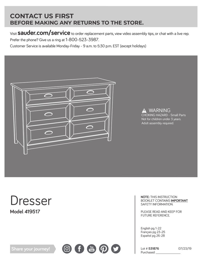
Sauder 410794 User manual

Sauder

Sauder 410794 User manual

Sauder Harbor View Armoire 415003 User manual

Sauder

Sauder Harbor View Armoire 415003 User manual

Sauder 422294 User manual

Sauder

Sauder 422294 User manual

Sauder 412321 User manual

Sauder

Sauder 412321 User manual

Sauder 415546 User manual

Sauder

Sauder 415546 User manual

Sauder WHISKER CAT PYRAMID User manual

Sauder

Sauder WHISKER CAT PYRAMID User manual

Sauder Sewing/Craft Cart User manual

Sauder

Sauder Sewing/Craft Cart User manual

Sauder Library 412177 User manual

Sauder

Sauder Library 412177 User manual

Sauder 427470 User manual

Sauder

Sauder 427470 User manual

Popular Indoor Furnishing manuals by other brands

Amart Furniture HARZ 71719 Assembly instruction

Amart Furniture

Amart Furniture HARZ 71719 Assembly instruction

Amart Furniture Winton 72062 Assembly instruction

Amart Furniture

Amart Furniture Winton 72062 Assembly instruction

Intercon CO-TA-I4870B Assembly instructions

Intercon

Intercon CO-TA-I4870B Assembly instructions

Steelcase Share It Collaborative 5 FH Assembly Directions

Steelcase

Steelcase Share It Collaborative 5 FH Assembly Directions

Walker Edison BTOT Assembly instructions

Walker Edison

Walker Edison BTOT Assembly instructions

BROSA Clem Sofa Bed Assembly guide

BROSA

BROSA Clem Sofa Bed Assembly guide

Walker Edison TW60H Assembly instructions

Walker Edison

Walker Edison TW60H Assembly instructions

DETAIL Mia DHS333-78 quick start guide

DETAIL

DETAIL Mia DHS333-78 quick start guide

Prepac Sonoma SC-3620 Assembly instructions

Prepac

Prepac Sonoma SC-3620 Assembly instructions

Forte PQRS92312 Assembling Instruction

Forte

Forte PQRS92312 Assembling Instruction

JWA FULLER 74631 Assembly instruction

JWA

JWA FULLER 74631 Assembly instruction

moovin BMU 58 Assembly instructions

moovin

moovin BMU 58 Assembly instructions

Vogue CM520 Assembly instructions

Vogue

Vogue CM520 Assembly instructions

U-Line H-7822 quick start guide

U-Line

U-Line H-7822 quick start guide

KI Doni Repair & Replacement Instructions

KI

KI Doni Repair & Replacement Instructions

Flash Furniture NAN-JN-2824S-GG Assembly instructions

Flash Furniture

Flash Furniture NAN-JN-2824S-GG Assembly instructions

Triarch 33223 installation instructions

Triarch

Triarch 33223 installation instructions

Swedstyle CLASSIC TWIN 2.0 FLEX-2022 Assembly instruction

Swedstyle

Swedstyle CLASSIC TWIN 2.0 FLEX-2022 Assembly instruction

manuals.online logo
manuals.online logoBrands
  • About & Mission
  • Contact us
  • Privacy Policy
  • Terms and Conditions

Copyright 2025 Manuals.Online. All Rights Reserved.