manuals.online logo
Brands
  1. Home
  2. •
  3. Brands
  4. •
  5. Sauder
  6. •
  7. Indoor Furnishing
  8. •
  9. Sauder Hammond 430786 User manual

Sauder Hammond 430786 User manual

sauder.com
NOTE: THIS INSTRUCTION
BOOKLET CONTAINS IMPORTANT
SAFETY INFORMATION.
PLEASE READ AND KEEP FOR
FUTURE REFERENCE.
sauder.com
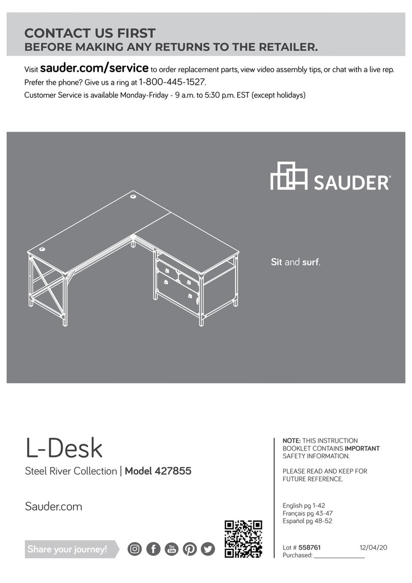
CONTACT US FIRST
BEFORE MAKING ANY RETURNS TO THE STORE.
sauder.com
CONTACT US FIRST
BEFORE MAKING ANY RETURNS TO THE RETAILER.
Visit sauder.com/service to order replacement parts, view video assembly tips, or chat with a live rep.
Prefer the phone? Give us a ring at 1-800-445-1527.
Customer Service is available Monday-Friday - 9 a.m. to 5:30 p.m. EST (except holidays)
Sauder.com
Share your journey!
English pg 1-38
Français pg 39-43
Español pg 44-48
Lot # 574794 11/22/21
Purchased: __________________
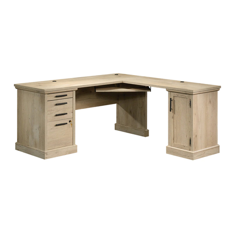
Computer Desk
Hammond Collection | Model 430786
For all your
newfangled gadgetry.
Part Identification
Hardware Identification
Hardware Usage Guide
Assembly Steps
Français
Español
Safety
Warranty
No. 2 Phillips Screwdriver
Tip Shown Actual Size
Table of Contents Assembly Tools Required
2-3
4-5
6
7-38
39-43
44-48
49-50
51
A TOP (1)
B BOTTOM (2)
C LEFT END (1)
D RIGHT END (1)
E LEFT UPRIGHT (1)
F RIGHT UPRIGHT (1)
G SHORT BRACE (1)
H BACK (2)
J ADJUSTABLE SHELF (1)
K DOOR (1)
L MODESTY PANEL (1)
M LEFT DRAWER SIDE (2)
N RIGHT DRAWER SIDE (2)
O DRAWER FRONT (2)
P DRAWER BOTTOM (2)
Q DRAWER BACK (2)
R LEFT KEYBOARD SIDE (1)
S RIGHT KEYBOARD SIDE (1)
T KEYBOARD SHELF (1)
U KEYBOARD FRONT (1)
V KEYBOARD BACK (1)
Z FOOT (8)
åWhile not all parts are labeled, some of the parts will have a label or an inked letter on the edge
to help distinguish similar parts from each other. Use this part identification to help identify similar parts.
Now you know
our ABCs.
Part Identification
Page 2 www.sauder.com/service 430786
Part Identification
A
B
C
D
E
F
G
H
J
K
L
M
N
O
P
Q
R
S
T
U
V
B
H
M
N
O
P
Q
Z
Z
Page 3www.sauder.com/service430786
Hardware Identification
åScrews are shown actual size. You may receive extra hardware with your unit.
APPLIQUE CARD - 5
10
LARGE WOOD
DOWEL - 54
8
KNOB SET - 5
11
SMALL WOOD
DOWEL - 16
9
HIDDEN
CAM - 34
5CAM SCREW - 42
7
SMALL HIDDEN
CAM - 8
6
FILE BAR
CLIP - 8
24
L-WRENCH - 1
19
HINGE - 2
13
RUBBER BUMPER- 2
23
MAGNETIC CATCH - 3
20
3EXTENSION RAIL - 2 4EXTENSION SLIDE - 2
2LONG EXTENSION
SLIDE - 4
1LONG EXTENSION
RAIL - 4
(EXTENSION SET SHOWN SEPARATED)(EXTENSION SET SHOWN SEPARATED)
FILE BAR - 4
25
STRIKE PLATE - 2
21
14 LARGE
GROMMET - 3
15 GROMMET - 2 GROMMET CAP- 1
16 SMALL GROMMET - 1
17
DOOR
HINGE - 2
12
CORD CLIP - 1
18
DOOR STRIKE
PLATE - 1
22
Page 4 www.sauder.com/service 430786
Hardware Identification
åScrews are shown actual size. You may receive extra hardware with your unit.
SHELF PIN - 4
26
1-3/8" FLAT HEAD SCREW - 20
28
1" MACHINE SCREW - 1
30 5/8" FLAT HEAD SCREW - 36
31
2-3/4" HEX HEAD SCREW - 16
27
1/2" FLAT HEAD SCREW - 24
33
NARROW 1/2" FLAT HEAD SCREW - 3
34
NARROW 5/8" FLAT HEAD SCREW - 6
32
1/2" MACHINE SCREW - 2
35
1-3/8" MACHINE SCREW - 2
29
HIDDEN WIRELESS Qi COMPATIBLE
CHARGER by EGGTRONIC - Item 425905
(sold separately)
p
o
w
e
r
e
d
b
y
E
G
G
T
R
O
N
I
C
p
o
w
e
r
e
d
b
y
E
G
G
T
R
O
N
I
C
p
o
w
e
r
e
d
b
y
E
G
G
T
R
O
N
I
C
p
o
w
e
r
e
d
b
y
E
G
G
T
R
O
N
I
C
Page 5www.sauder.com/service430786
Hardware Usage Guide
HOW TO USE A HIDDEN CAM & CAM SCREW OR CAM DOWEL
NOTE: Various CAM SCREWS or a CAM DOWEL may be used.
Cam Screws Cam Dowel
Turn the CAM SCREW or
gently tap the CAM DOWEL
until the shoulder is against
the surface of the part.
1.
Hidden Cam
Arrow
Push a HIDDEN CAM into
the part. The arrow in the
HIDDEN CAM must point
toward the hole in the
edge of the board.
Hole
2.
3.
1
2
Insert the CAM SCREW or CAM DOWEL into the
HIDDEN CAM. Tighten the HIDDEN CAM.
Page 6 www.sauder.com/service 430786
Step 1
å Assemble your unit on a carpeted floor or on the empty
carton to avoid scratching your unit or the floor.
å Turn five CAM SCREWS (7) into the exact holes shown in
both surfaces of the LEFT UPRIGHT (E).
å Then, push four HIDDEN CAMS (5) into the LEFT
UPRIGHT (E).
Look for this icon. It means a video assembly tip is
available at www.sauder.com/service/tips
Find the numbered video or scan the QR code.
E
E
F
L
I
P
O
V
E
R
E
1
Some assembly
(and snacks) required.
5
Arrow
Arrow
5
7
7
Page 7www.sauder.com/service430786
StepStep 2
E
å Separate the EXTENSION SLIDES (4) from the EXTENSION RAILS (3) as shown in the upper diagram below. Be
prepared, the parts are greasy.
å Fasten an EXTENSION RAIL (3) to the LEFT UPRIGHT (E). Use three 5/8" FLAT HEAD SCREWS (31).
å NOTE: For the EXTENSION RAIL, turn a SCREW into the hole shown in the diagram. Then, slide the inner cartridge of
the EXTENSION RAIL in to find the other holes that lines up with the holes in the LEFT UPRIGHT. Turn a SCREW into
these holes.
å NOTE: The EXTENSION SLIDES will be used later for the KEYBOARD SHELF.
Use these holes.
BLACK 5/8" FLAT HEAD SCREW
(3 used in this step)
31
7
Push the black lever and pull
the SLIDE from the RAIL.
3
4
3
Closed end
Closed end
Molding
Surface without
HIDDEN CAMS
Page 8 www.sauder.com/service 430786
å Turn two CAM SCREWS (7) into the exact holes shown in
the LEFT END (C).
å Then, push eight HIDDEN CAMS (5) into the LEFT
END (C) and one of the BACKS (H).
Step 3
H
C
1
5
Arrow
Arrow
5
7
Arrow 5
5
Arrow
Page 9www.sauder.com/service430786
å Insert four LARGE WOOD DOWELS (8) into the long
edges of the BACK (H).
å Fasten the BACK (H) to the LEFT END (C) and LEFT
UPRIGHT (E). Tighten four HIDDEN CAMS.
å NOTE: Be sure the WOOD DOWELS in the BACK insert
into the holes in the LEFT END and LEFT UPRIGHT.
Step 4 1
8
H
C
E
Surface with
HIDDEN CAMS
Surface with
HIDDEN CAMS
Surface without
HIDDEN CAMS
(4 used)
Molding
Molding
Page 10 www.sauder.com/service 430786
å Turn six CAM SCREWS (7) into the exact holes shown in
both surfaces of the RIGHT UPRIGHT (F).
å Then, push four HIDDEN CAMS (5) into the RIGHT
UPRIGHT (F).
Step 5 1
F
F
F
L
I
P
O
V
E
R
F
5
Arrow
Arrow
5
7
7
Page 11www.sauder.com/service430786
å Fasten the other EXTENSION RAIL (3) to the RIGHT
UPRIGHT (F). Use three 5/8" FLAT HEAD SCREWS (31).
å NOTE: For the EXTENSION RAIL, turn a SCREW into the
hole shown in the enlarged diagram. Then, slide the inner
cartridge of the EXTENSION RAIL in to find the other
holes that lines up with the holes in the RIGHT UPRIGHT.
Turn a SCREW into these holes.
Step 6
Use these holes.
BLACK 5/8" FLAT HEAD SCREW
(3 used in this step)
31
3Closed end
3
F
Molding
Closed end
Surface without
HIDDEN CAMS
Page 12 www.sauder.com/service 430786
å Separate the LONG EXTENSION SLIDES (2) from the LONG EXTENSION RAILS (1) as shown in the upper diagram
below. Be prepared, the parts are greasy.
å Fasten two LONG EXTENSION RAILS (1) to the other surface of the RIGHT UPRIGHT (F). Use six 5/8" FLAT
HEAD SCREWS (31).
å NOTE: For each LONG EXTENSION RAIL, turn a SCREW into the hole shown in the diagram. Then, slide the inner
cartridge of the EXTENSION RAIL in to find the other holes that lines up with the holes in the RIGHT UPRIGHT. Turn a
SCREW into these holes.
å NOTE: The LONG EXTENSION SLIDES will be used later for the DRAWERS.
Step 7
Use these holes.
Push the black lever and pull
the SLIDE from the RAIL.
1
2Closed end
7
BLACK 5/8" FLAT HEAD SCREW
(6 used in this step)
31
1
1
Closed end
Molding
Closed end
F
Surface with
HIDDEN CAMS
Page 13www.sauder.com/service430786
å Turn three CAM SCREWS (7) into the exact holes shown
in the RIGHT END (D).
å Then, push four HIDDEN CAMS (5) into the RIGHT
END (D).
Step 8
D
5
Arrow
Arrow
5
7
7
1
Page 14 www.sauder.com/service 430786
å Fasten the other two LONG EXTENSION RAILS (1) to the
RIGHT END (D). Use six 5/8" FLAT HEAD SCREWS (31).
å NOTE: For each LONG EXTENSION RAIL, turn a SCREW
into the hole shown in the diagram. Then, slide the inner
cartridge of the EXTENSION RAIL in to find the other
holes that lines up with the holes in the RIGHT END. Turn a
SCREW into these holes.
Step 9
5/8" FLAT HEAD SCREW
(6 used in this step)
31
1
1
Molding
D
Surface with
HIDDEN CAMS
Use these holes.
1Closed end
Closed end
Page 15www.sauder.com/service430786
å Push six HIDDEN CAMS (5) into the SHORT BRACE (G)
and the other BACK (H).
Step 10
H
Arrow 5
5
Arrow
1
G
Page 16 www.sauder.com/service 430786
å Insert six LARGE WOOD DOWELS (8) into the short
edges of the SHORT BRACE (G) and the long edges
of BACK (H).
å Fasten the SHORT BRACE (G) and BACK (H) to the
RIGHT END (D) and RIGHT UPRIGHT (F). Tighten six
HIDDEN CAMS.
å NOTE: Be sure the WOOD DOWELS in the SHORT
BRACE and BACK insert into the holes in the RIGHT END
and RIGHT UPRIGHT.
Step 11
H
G
8
Surface with
HIDDEN CAMS
Surface with
HIDDEN CAMS
Surface without
HIDDEN CAMS
(6 used)
Molding
Molding
F
D
8
Surface with
HIDDEN CAMS
1
Page 17www.sauder.com/service430786
Notched edge
å Insert sixteen LARGE WOOD DOWELS (8) into large holes in the FEET (Z).
å Fasten four FEET (Z) to each BOTTOM (B). Tighten sixteen BLACK 2-3/4" HEX HEAD SCREWS (27)
using the L-WRENCH (19).
å NOTE: Be sure the WOOD DOWELS in the FEET insert into the holes in the BOTTOMS.
å Insert a LARGE GROMMET (14) into the large holes in the BOTTOMS (B).
Step 12
B
19
8
Z
14
Z
Z
Z
B
Z
14
Z
Z
Z
8
(16 used)
Meet Part (B). This component has
been engineered to be lighter, stronger,
faster… well ok. Not technically faster. But
definitely makes for a sturdier Computer
Desk that’s easier to assemble and
friendlier to the environment.
Page 18 www.sauder.com/service 430786
BLACK 2-3/4" HEX HEAD SCREW
(16 used in this step)
27
å Turn eight CAM SCREWS (7) into the exact holes shown
in the BOTTOMS (B).
Step 13
B
7
B
7
1
Page 19www.sauder.com/service430786
å Insert eight LARGE WOOD DOWELS (8) into the
BOTTOMS (B).
å With someone's help, fasten the ENDS (C and D) and
UPRIGHTS (E and F) to the BOTTOMS (B) as shown.
Tighten eight HIDDEN CAMS.
å NOTE: Be sure the WOOD DOWELS in the BOTTOMS
insert into the holes in the ENDS and UPRIGHTS.
Step 14 1
B
B
F
D
C
EH
H
8
Angled edge
Angled edge
(8 used)
Page 20 www.sauder.com/service 430786

Other Sauder Indoor Furnishing manuals

Sauder Carson Forge 416969 User manual

Sauder

Sauder Carson Forge 416969 User manual

Sauder North Avenue 420035 User manual

Sauder

Sauder North Avenue 420035 User manual

Sauder Trestle 424127 User manual

Sauder

Sauder Trestle 424127 User manual

Sauder North Avenue 425190 User manual

Sauder

Sauder North Avenue 425190 User manual

Sauder Anda Norr 427346 User manual

Sauder

Sauder Anda Norr 427346 User manual

Sauder Armoire 419451 User manual

Sauder

Sauder Armoire 419451 User manual

Sauder 413322 User manual

Sauder

Sauder 413322 User manual

Sauder Heritage Hill Lateral File 102702 User manual

Sauder

Sauder Heritage Hill Lateral File 102702 User manual

Sauder Harvey Park 414986 User manual

Sauder

Sauder Harvey Park 414986 User manual

Sauder 422294 User manual

Sauder

Sauder 422294 User manual

Sauder Boulevard Cafe 427354 User manual

Sauder

Sauder Boulevard Cafe 427354 User manual

Sauder 109872 User manual

Sauder

Sauder 109872 User manual

Sauder Harbor View 423661 User manual

Sauder

Sauder Harbor View 423661 User manual

Sauder Cannery Bridge 431315 User manual

Sauder

Sauder Cannery Bridge 431315 User manual

Sauder Tremont Row 427971 User manual

Sauder

Sauder Tremont Row 427971 User manual

Sauder 404958 User manual

Sauder

Sauder 404958 User manual

Sauder Harvey Park Lateral File 426510 User manual

Sauder

Sauder Harvey Park Lateral File 426510 User manual

Sauder Barrister Lane 414720 User manual

Sauder

Sauder Barrister Lane 414720 User manual

Sauder Boulevard Cafe 420701 User manual

Sauder

Sauder Boulevard Cafe 420701 User manual

Sauder Harbor View 420474 User manual

Sauder

Sauder Harbor View 420474 User manual

Sauder 409048 User manual

Sauder

Sauder 409048 User manual

Sauder Barrister Lane 414108 User manual

Sauder

Sauder Barrister Lane 414108 User manual

Sauder Englewood 426909 User manual

Sauder

Sauder Englewood 426909 User manual

Sauder Harbor View 403793 User manual

Sauder

Sauder Harbor View 403793 User manual
Popular Indoor Furnishing manuals by other brands

Vamol Classic Monet 010064150 Assembly instructions

Vamol

Vamol Classic Monet 010064150 Assembly instructions

Landscape Forms GO installation guide

Landscape Forms

Landscape Forms GO installation guide

RSA Lighting QCT904RMMH specification

RSA Lighting

RSA Lighting QCT904RMMH specification

Dorel Home Products 4087419WE manual

Dorel Home Products

Dorel Home Products 4087419WE manual

noken LOUNGE 100211072 N859000073 installation instructions

noken

noken LOUNGE 100211072 N859000073 installation instructions

Haworth Upside installation instructions

Haworth

Haworth Upside installation instructions

Trasman 1650 Bo5 Instruction guide

Trasman

Trasman 1650 Bo5 Instruction guide

MP GLASS BISHOP Assembly

MP GLASS

MP GLASS BISHOP Assembly

PROGRESSIVE DESK FLT-07 user guide

PROGRESSIVE DESK

PROGRESSIVE DESK FLT-07 user guide

U-Line H-5498 manual

U-Line

U-Line H-5498 manual

Friant Verity installation manual

Friant

Friant Verity installation manual

PENCO Stadium 86190 Assembly instructions

PENCO

PENCO Stadium 86190 Assembly instructions

Multimo A228-ROYAL Assembly instructions

Multimo

Multimo A228-ROYAL Assembly instructions

Cheyenne Products CPFB1657 Assembly instructions

Cheyenne Products

Cheyenne Products CPFB1657 Assembly instructions

FMD Furniture ESSEX 1 641-001 Assembly instructions

FMD Furniture

FMD Furniture ESSEX 1 641-001 Assembly instructions

Balt LX-72B Assembly instructions

Balt

Balt LX-72B Assembly instructions

Meble Wojcik HOBBY PRO-018-3101 Assembly instructions

Meble Wojcik

Meble Wojcik HOBBY PRO-018-3101 Assembly instructions

kupper 12250 Assembly instruction

kupper

kupper 12250 Assembly instruction

manuals.online logo
manuals.online logoBrands
  • About & Mission
  • Contact us
  • Privacy Policy
  • Terms and Conditions

Copyright 2025 Manuals.Online. All Rights Reserved.