ENGLISH 9
50
60
90
50
60
60
20
20
20
20
20
20
40
50
80
40
50
50
140
140
140
90
90
90
MN-23NB-DRF
MN-30NB-DRF
MN-36NB-DRF
MN-23NS-DRF
MN-30NS-DRF
MN-36NS-DRF
A B C D
155
155
155
155
155
155
E
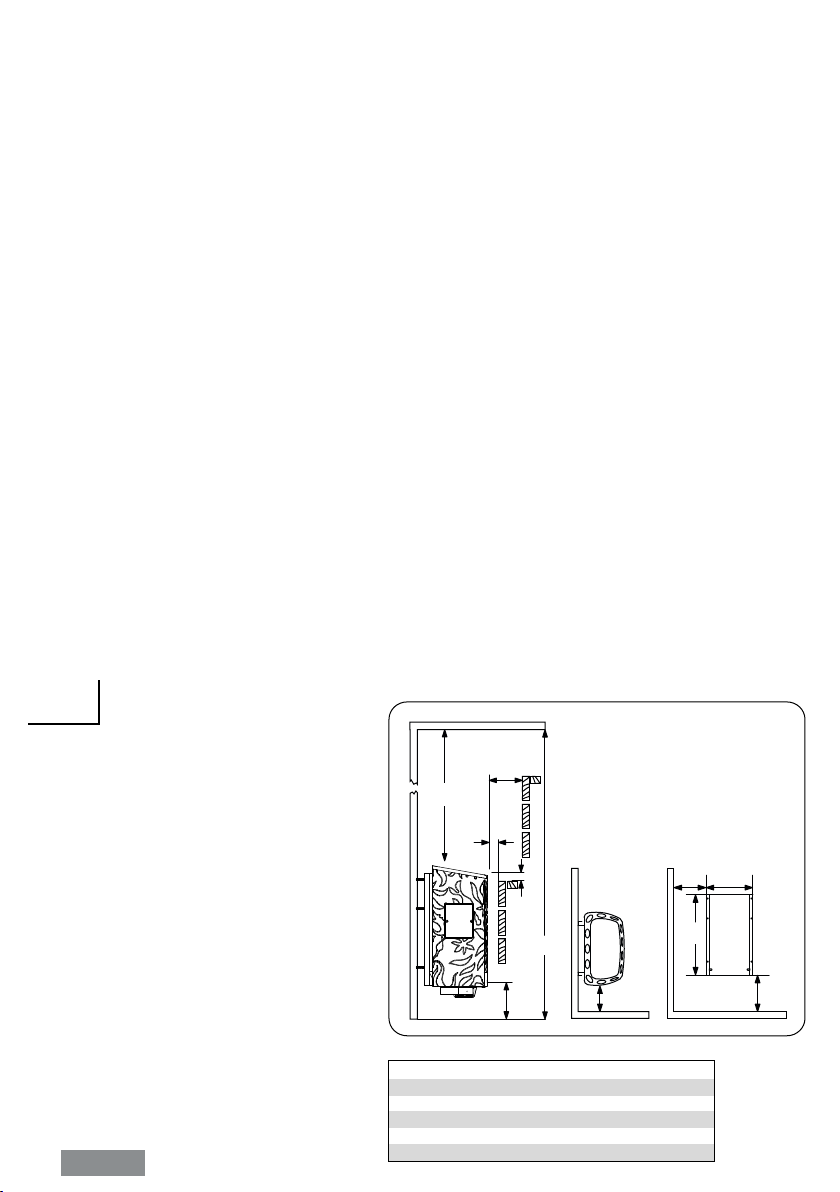
Wall Mounting Rack Installation
1900
150
1200
A
B
20
225
380
C E
D
HEATER INSTALLATION
It is recommended that the heater be placed on the wall nearest to the door. The air circulation
created by the door should work together with the hot air generated by the heater. For safety
and convenience, follow the minimum safety distances as provided (See Fig 1.). Follow the cubic
volumes (See page 11). Do not install the heater to the oor or wall niche. Install only one heater
in a sauna room.
Be sure to build a strong foundation for the mounting rack (e.g. cross struts in sauna paneling) or
reinforce the wall with a thick board to prevent the heater from collapsing. Attach the heater to the
wall with the aid of the mounting rack. Screws (6 pieces) are provided for fastening of the rack to
the wall. To afx the heater to the rack, lift the heater and t the nuts that are placed at the back
of the heater to the slots on both sides at the top of the rack. Lock at least one of the side screws
to prevent the heater from being accidentally moved.
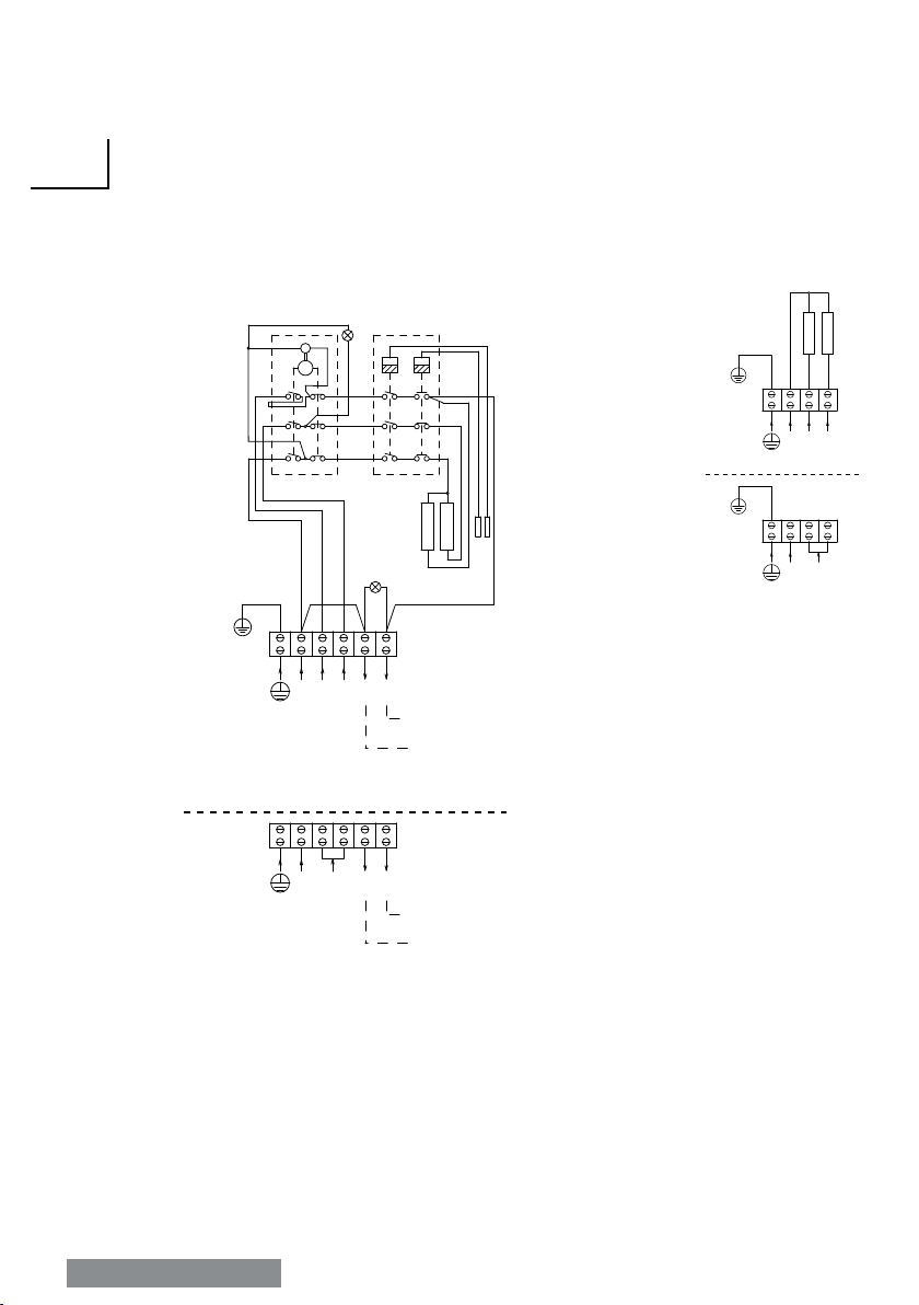
A certied electrician must do the installation of the heater to ensure safety and reliability. Improper
electrical connections can cause electric shock or re. Refer to the electrical diagram See page <?>.
An electrical supply cable must be connected to the terminal block inside the control unit through
the cable channel. The cable must be H07RN-F type or its equivalent. To connect the cable, the
control unit must be opened (See page 12). First, pull the temperature knob outward to uncover
the screws that hold the plastic cover. Second, remove the set of screws under the temperature
knob and at the bottom (both sides) of the control unit. Detach the front plastic cover and nally
insert the electrical supply cable into the cable channel by simply slipping it through the hole at the
bottom of the channel towards the opening at the other end (See page 12). Install the cables
tightly to the terminal block. Put back the front plastic cover, screws and temperature knob.
The heater gets very hot. To avoid the risk of accidental contact with the heater, it is recommended
that a heater guard be provided. Reserve enough space for operation of the timer and thermostat
knobs.
Kuva 2
Fig. 2
Ruuvi
Screw
Kehys
Frame
Löylynohjain
Reector
Make sure that the heat
reector shield is placed
at the back part of the
heater frame.
Varmista että löylynohjain
on asennettu kiukaan ke-
hyksen takaosaan.
Löylynohjaimen asennus
(valinnainen)
How to install the reector
(Optional)
Min.20
Min.20
Min.20