Sealey YK30XF User manual

2. INTRODUCTION
1. SAFETY
1.1 GENERAL SAFETY
Familiarise yourself with this products application and limitations, as well as the specific potential hazards peculiar to the press.
Maintain the press in good condition (use an authorised service agent).
Replace or repair damaged parts. Use recommended parts only. Non authorised parts may be dangerous and will invalidate the
warranty.
Keep the press clean for best and safest performance.
Locate the press in a suitable working area for its function, keep area clean, tidy, free from unrelated materials and ensure there is
adequate lighting.
Ensure the workpiece is correctly secured before operating the press.
WARNING! Always wear approved eye or face protection when operating the press.
Remove ill fitting clothing. Remove ties, watches, rings, loose jewellery and contain long hair.
Keep hands and body clear of the work table when operating the press.
Maintain correct balance and footing. Ensure the floor is not slippery and wear non-slip steel toe-capped shoes/boots.
Keep children and unauthorised persons away from the working area.
DO NOT operate the press if any parts are missing as this may cause failure and/or possible personal injury.
DO NOT use to compress springs or any other item that could disengage and cause a potential hazard.
DO NOT stand directly in front of the loaded press and never leave a loaded press unattended.
DO NOT use the press for any purpose other than that for which it is designed.
DO NOT make any modifications to the press.
DO NOT adjust or tamper with the safety valve.
DO NOT exceed the rated capacity of the press.
DO NOT apply off-centre loads.
DO NOT allow the workpiece or the press plates to fall from the work table.
DO NOT get the press wet or use in damp or wet locations or areas where there is condensation.
DO NOT operate the press when you are tired or under the influence of alcohol, drugs or intoxicating medication.
When not in use,release pressure from the hydraulic unit and clean the press. Stand or store the anvil "V" blocks in a safe location.
WARNING! Always position the press against a wall. If the press is situated in the open workshop, it is essential that a guard be
placed at the rear of the unit. This will prevent injury to bystanders in the event of the workpiece ejecting suddenly.
WARNING! The warnings, cautions and instructions in this manual cannot cover all possible conditions and situations that
may occur. It must be understood by the operator that common sense and caution are factors which cannot be built into this
product, but must be applied by the operator.
DANGER! When assembling, lifting or moving the press, it is recommended that it is by two people.
INSTRUCTIONS FOR:
30TONNE HYDRAULIC PRESS FLOOR
TYPE
MODEL NO: YK30XF
Self assembly Heavy Duty floor mounted press with hydraulic unit and single acting internal return spring return actuator (ram). Constructed from
structural steel and mild steel plates, fabricated for strength. Powder coated paint finish frames and plated fixings. Supplied with a pair of
V-blocks/pressing plates, separate pump operating handle and load/pressure gauge.
3. SPECIFICATIONS
IMPORTANT: PLEASE READ THESE INSTRUCTIONS CAREFULLY. NOTE THE SAFE OPERATIONAL REQUIREMENTS, WARNINGS & CAUTIONS. USE THE
PRODUCT CORRECTLY AND WITH CARE FOR THE PURPOSE FOR WHICH IT IS INTENDED. FAILURE TO DO SO MAY CAUSE DAMAGE AND/OR PERSONAL
INJURY AND WILL INVALIDATE THE WARRANTY. KEEP THESE INSTRUCTIONS SAFE FOR FUTURE USE.
Thank you for purchasing a Sealey product. Manufactured to a high standard, this product will, if used according to these
instructions, and properly maintained, give you years of trouble free performance.
Model:................................................................ YK30XF
Floor Mounting:.......................................................... Yes
Type:................................................................. Hydraulic
Capacity:............................................................. 30tonne
Ram Stroke:......................................................... 150mm
Ram Diameter:....................................................... 80mm
*Lateral Ram Travel:..............................................200mm
**Maximum Height - Ram to Table:.........1100mm approx.
**Minimum Height - Ram to Table:...........110mm approx.
Table Aperture:..................................................... 154mm
Work Table Depth:............................................... 284mm
Work Table Width:............................................... 460mm
Overall Height:....................................................1908mm
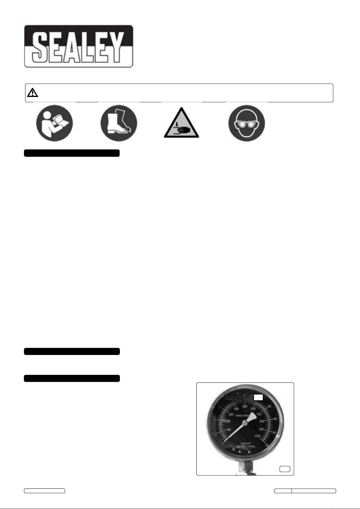
Gauge Included:......................................................... Yes
Weight:.................................................................141.5kg
Gauge graduated in load and pressure
30
g.1
*See also g.2 for ram lateral adjustment.
**See also g.2 for clear opening height max. and min.
YK30XF Issue No: 2(I) - 15/04/15
Original Language Version
© Jack Sealey Limited
Read the instruction manual Wear safety shoes Beware crushing hands Wear eye protection

4. ASSEMBLY
YK30XF Issue No: 2(I) - 15/04/15
Original Language Version
© Jack Sealey Limited
**110 min
**1100 max
4.1 Contents:
4.1.1 Unpack the product and check contents against the item list. Should there be any damaged or missing parts contact your Sealey Dealer
immediately. Refer to the appropriate parts diagram as a guide to assembly, read all notes prior to assembly.
4.1.2 Place the upright frames (1) horizontally on a bench and fit the base frame
angles (2) and strut/ties (4) with fixings (19, 20, 21) loosely.
4.1.3 Stand and support the sub assembled upright frames on a horizontal
workshop floor and fit the spacer angle (3) with fixings (19, 20, 21) loosely.
4.1.4 Pass the height control bars (7) through the upright frames at the desired
height. [The holes are pitched at 110mm offering clear opening heights of
approximately 110mm to 1100mm in 9 steps of 110mm].
4.1.5 Fit the quick release spring type circlips (28) to the bars (7). The clips need to
be equi-distant from the upright frame sides for the table (5) placement.
4.1.6 Place the channel section table (5) on to the height control bars (7). The table
is extremely heavy and only the user can decide the safest method of
placement.
4.1.7 Fit the channel section top frame (6) with fixings (22, 23, 24) loosely. The
top frame is extremely heavy and only the user can decide the safest
method of placement.
4.1.8 With a good quality builders level and the assembled frame standing on a flat
level surface, ensure that the frame details are supported upright whilst all
frame fixings are tightened.
4.1.9 On the workbench, fit the actuator (15) into the actuator mounting plate (8)
with the four socket head cap screws (14).
4.1.10 Fit the slide bar shoes (11) to the slide bar (10), place the compression
springs (16) on to the hexagon head bolts (17) and place on to the slide bar.
4.1.11 The actuator sub assembly must be offered from beneath the top frame and
the slide bar from above. Clamp together with the M10 X 110 hexagon head
screws (17), screw in full depth and pinch screw with socket set screws (18).
Check the actuator sub assembly will slide, if not slacken screws slightly.
The actuator sub assembly is extremely heavy and only the user can
decide the safest method of placement.
4.1.12 Fit the pump (15B) with fixings (25, 26) and connect the hydraulic hose (15C)
and pressure gauge (15D).
4.1.13 Locate the press and anchor to a level workshop floor with suitable fixings (not
supplied).
4.1.14 Place "Vee" blocks (13) on the worktable top ready for use, with the heel block
pads in the gap provided by the channel sections (5). This will help prevent
accidental dropping when sliding into position.
1
2
3
4
5
6
7
8
10
11
610
12
13
14
15B
19, 20, 21
15B
15A
16
17 18
22
23
24
25
26
27
14
28
Item Description Qty
1 [11] Upright frame fabrication 2
2 [9] Base frame angles 2
3 [13] Spacer angle 1
4 [5] Strut/tie 4
5 [2] Channel section table fabrication 1
6 [20] Channel section top frame fabrication 1
7 [4] Height control bar 2
8 [15] Actuator (ram) mounting plate 1
9 [15] Actuator (ram) shoulder collar 1
10 [26] Mounting plate slide bar 2
11 [24] Slide bar shoes 4
12 [15] Actuator (ram) collar 1
13 [1] "Vee" block/plattens (loose) 2
14 [39] Pump operating lever (loose) 1
15 [32-5] Actuator/gauge/hose/pump unit. 1
16 [27] Compression spring 4
17 [28] Hex head bolt M10 X 110 4
18 [14] Soc head set screw M6 4
19 [10] Hex head screw M12 X 30 12
20 [8] Hex nut M12 12
21 [6,7] Washer Ø12 24
22 [19] Hex head screw M20 X 50 8
23 [23] Hex nut M20 8
24 [21] Plain washer Ø20 16
25 [37] Hex head screw M10 X 25 4
26 [38] Plain washer Ø10 4
27 [14] Socket set cap screws 4
28 [3] Quick release circlips 4
(Numbers in brackets taken from parts diagram).
*200mm
6
4.1.11
4.1.12 4.1.2
4.1.10 4.1.7
Top frame viewed from ends
Release valve
4.1.3
1
2
4.1.14
13
"Vee" blocks ush face uppermost
4
g.2
15D
"..upright frames (1) horizontally on a bench.."

NOTE: It is our policy to continually improve products and as such we reserve the right to alter data, specifications and component parts without prior notice.
IMPORTANT: No liability is accepted for incorrect use of product.
WARRANTY: Guarantee is 12 months from purchase date, proof of which will be required for any claim.
INFORMATION: For a copy of our latest catalogue and promotions call us on 01284 757525 and leave your full name and address, including postcode.
IMPORTANT: NO RESPONSIBILITY IS ACCEPTED FOR INCORRECT USE OF THE PRESS.
Hydraulic products are only repaired by local service agents. We have service/repair agents in all parts of the UK.
DO NOT RETURN PRODUCT TO US. Please telephone us on 01284 757500 to obtain the address and phone number of your local agent.
If product is under guarantee please contact your dealer.
De-commissioning Product
Should the product become completely unserviceable and require disposal, draw off the oil into an approved container and dispose of the
product and the oil according to local regulations.
Sole UK Distributor, Sealey Group,
Kempson Way, Suffolk Business Park,
Bury St. Edmunds, Suffolk,
IP32 7AR
01284 757500
01284 703534
sales@sealey.co.uk
www.sealey.co.uk
Web
email
6. MAINTENANCE
Note: Maintenance and repair must only be carried out by a qualified person. Contact your Sealey dealer for details.
6.1 Always keep the press clean, dry and lubricate all moving parts at regular intervals.
6.2 When not in use the hydraulic unit must be fully retracted.
6.3 Should you need to check or replace oil, ensure the hydraulic unit is fully retracted. Remove the oil reservoir filler plug and top
up using Sealey hydraulic jack oil (Sealey Part No's: HJO500MLS/HJO5LS). DO NOT use brake fluid. After filling, purge the system
as described in Section 5.1 to remove any air.
DANGER! The press is purpose designed to withstand greater loads than the hydraulic unit can develop. For safety reasons,
always ensure the workpiece is secured on the worktable to ensure loads that flex will not suddenly “give” causing danger to
operator or damage to component. Ensure you have read and understood Section 1 safety instructions.
5.1 Before operating the press, purge the hydraulic system in order to eliminate any air that may have built up during transit. Open the
release valve and pump the handle several times (suggested 20 times). Should the system malfunction at any time, repeating this
process may resolve the problem. If not refer to Maintenance heading 6.3.
5.2 Place the "Vee" blocks (13) onto the worktable, then place workpiece onto the "Vee" blocks Note: Care must be taken to ensure that the
"Vee" blocks do not fall from the worktable. If necessary hold the configuration in position with clamps.
5.3 Select a suitable mandrel for the task, the supplied mandrel is shown in fig.3. Ask your Sealey dealer about available mandrels. Secured
by a socket set screw with a 3mm hex socket.
5.4 Turn the control valve knob clockwise to close valve.
5.5 Pump handle to apply load to the workpiece.Observe work and gauge (fig.1). DO NOT exceed the maximum load of 30tonne.
WARNING! DO NOT apply off-centre loads. The position of the actuator (ram) can be adjusted laterally +/- 100mm; the "Vee" blocks will
require repositioning equally about the actuator (ram) centre line.
5.6 When the work is done, stop pumping the handle. Slowly and carefully release load from workpiece by turning control valve knob
anticlockwise, in small increments.
5.7 Once the hydraulic unit has been fully retracted, remove the workpiece from the press. Note: Always keep the hydraulic unit fully
retracted after use to avoid ram corrosion.
5. OPERATION
Environmental Protection
Recycle unwanted materials instead of disposing of them as waste. All tools, accesso-
ries and packaging should be sorted, taken to a recycling centre and disposed of in a
manner which is compatible with the environment.
Ø25
Ø22
18
8 3
Ø58
Supplied plain mandrel with mandrel adaption dimensions
g.3
Parts support is available for this product. To obtain a parts listing and/or diagram,
please log on to www.sealey.co.uk, email sales@sealey.co.uk or telephone 01284 757500.
YK30XF Issue No: 2(I) - 15/04/15
Original Language Version
© Jack Sealey Limited
Table of contents
Other Sealey Power Tools manuals

Sealey
Sealey CP3005.V2 User manual

Sealey
Sealey SB974.V3 User manual

Sealey
Sealey AK624 User manual

Sealey
Sealey SA21/S.V3 User manual

Sealey
Sealey YK509F.V2 User manual

Sealey
Sealey CB50.V2 User manual

Sealey
Sealey SDL11 User manual

Sealey
Sealey PPF301 User manual

Sealey
Sealey STW802 User manual

Sealey
Sealey YC10B.V3 User manual

Sealey
Sealey CP313X User manual

Sealey
Sealey CP108VCRW User manual

Sealey
Sealey CP1440 User manual

Sealey
Sealey YK6ECB.V2 User manual

Sealey
Sealey SMS2008 User manual

Sealey
Sealey SA390 User manual

Sealey
Sealey STW300 User manual

Sealey
Sealey YK20FAH.V3 User manual

Sealey
Sealey SA2003KIT User manual

Sealey
Sealey SA7/SAS User manual