manuals.online logo
Brands
  1. Home
  2. •
  3. Brands
  4. •
  5. Sealey
  6. •
  7. Service Equipment
  8. •
  9. Sealey RE230UK User manual

Sealey RE230UK User manual

INSTRUCTIONS FOR: CONVERSION KIT
FOR RE230 SPRING COMPRESSOR
MODEL NO: RE230UK
Thank you for purchasing a Sealey product. Manufactured to a high standard this product will, if used according to these instructions
and properly maintained, give you years of trouble free performance.
IMPORTANT: PLEASE READ THESE INSTRUCTIONS CAREFULLY. NOTE THE SAFE OPERATIONAL REQUIREMENTS, WARNINGS & CAUTIONS.
USE THE PRODUCT CORRECTLY AND WITH CARE FOR THE PURPOSE FOR WHICH IT IS INTENDED. FAILURE TO DO SO MAY CAUSE
DAMAGE AND/OR PERSONAL INJURY AND WILL INVALIDATE THE WARRANTY. PLEASE KEEP INSTRUCTIONS SAFE FOR FUTURE USE.
GENERAL SAFETY.
!WARNING! Ensure Health & Safety, local authority, and
general workshop practice regulations are adhered to
when using this equipment.
!WARNING! Wear approved safety hand and eye
protection (standard spectacles are not adequate).
!WARNING! TRAPPING DANGER – Keep hands and fingers
away from the spring and compressing jaws when in use.
"Keep the work area clean, uncluttered and ensure there
is adequate lighting.
"Maintain correct balance and footing. Ensure the floor is
not slippery and wear non-slip shoes.
"Remove ill-fitting clothes. Remove ties, watches, rings,
other loose jewellery. Contain and/or tie back long hair.
"Wear appropriate protective clothing.
"Familiarise yourself with the applications, limitations and
potential hazards of the spring compressor.
#DO NOT use the spring compressor for a task it is not
designed to perform.
#DO NOT allow untrained persons to use the spring
compressor.
PRE OPERATIONAL SAFETY.
"Strut and Spring Compression station should be securely
bolted to the workshop floor before use.
"Apply grease to the front and rear faces of the main upright
to assist the smooth action of the compressor.
#DO NOT operate spring compressor if parts are damaged
or missing as this may cause failure and/or personal injury.
"Before commencing compression, make visual inspection
of machine to ensure pins are securely positioned and that
there is no sign of wear or fatigue – if found, do not use the
unit and refer to your local Sealey dealer for advice and
replacement parts.
"Ensure jaw locating pins are properly positioned and safety
clips are attached correctly.
"Before commencing compression of spring, ensure coils of
the spring are seated securely in the jaws of the
compressor and cannot slide out during compression.
"Always fit a safety chain around strut and spring (ensure
chain is not trapped in the coils of the spring being
compressed).
OPERATIONAL SAFETY.
"When applying compression to the spring, always stand to
one side of the unit.
$DANGER! Do not put hands or fingers near the spring as it is
being compressed.
$DANGER! Stop compressing the spring before the coils touch.
"Before attempting to remove top cap nut, always use a tool
or short stick to test if the compression has been relieved.
Do not use your hands / fingers.
"Sealey recommends the use of purpose made strut tools to
remove the top-nut from the shock absorber piston.
"Once compressed, and the strut removed, we recommend
releasing the tension on the spring. Do not leave the spring
under compression in the machine unattended and do not
leave in compression for prolonged periods i.e. overnight.
"Before releasing the compression ensure that the top
strut-nut is securely fastened to the maker’s tolerance.
"Release the compression slowly keeping your hands and
fingers away from the spring assembly.
"Be sure that the tension on the spring is fully controlled by
1. SAFETY INSTRUCTIONS
3. TECHNICAL SPECIFICATION
Maximum Load . . . . . . . . . . . . . . . . . . . . . . . . . . . . . .1000kg
Lower Yoke Travel . . . . . . . . . . . . . . . . . . . . . . . . . . .340mm
Spring Diameters . . . . . . . . . . . . . . . . . . . . . . . .102-160mm
Upper Yoke positions . . . . . . . . . . . . . . . . . . . . . . . . . . . . . .7
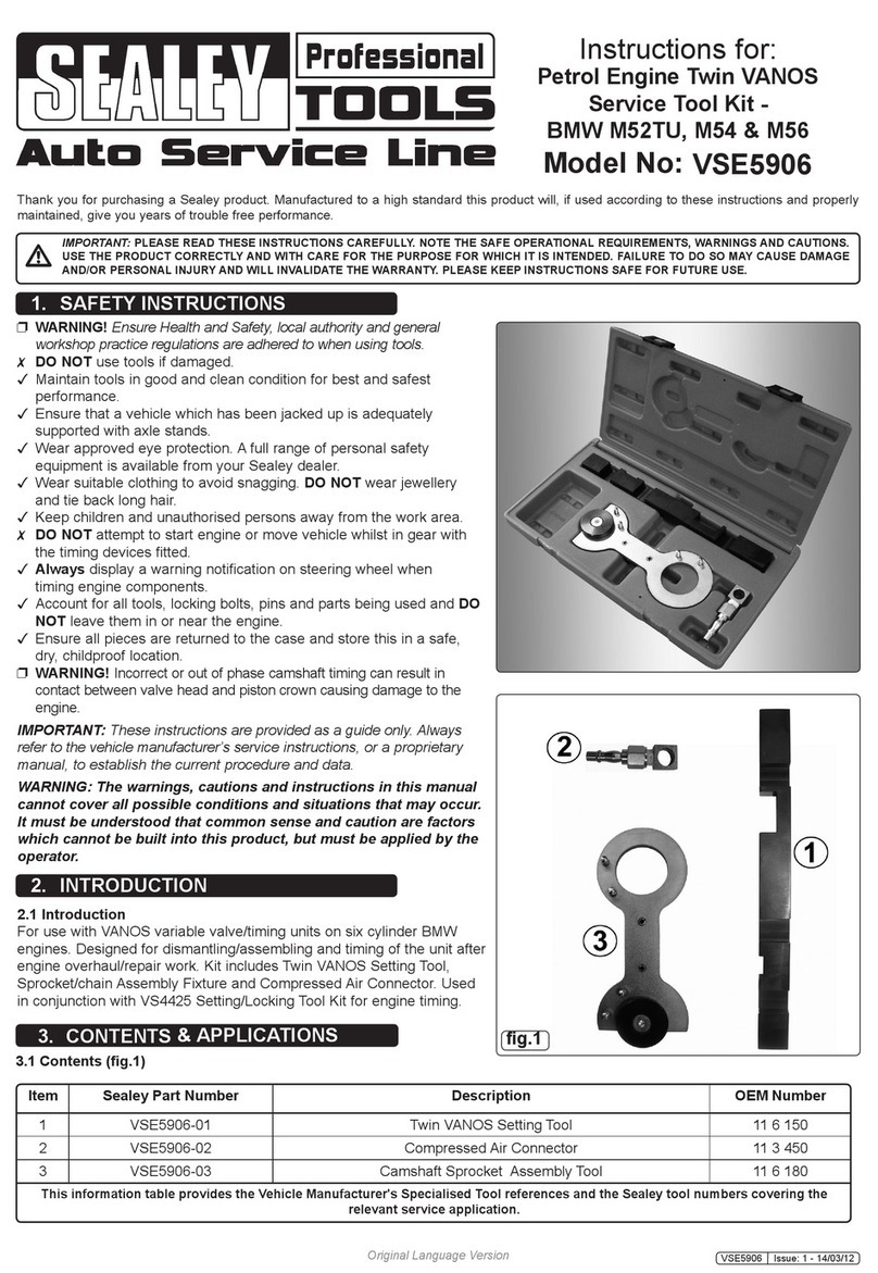
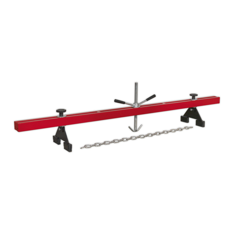
2.1 The RE230UK kit enables owners of the RE230 spring
compressor to fit an improved type of clamping jaw to their
existing units ( See figs.1 & 2 below ). This system allows
removal of the shock absorber from the spring without the
need to remove the assembly from the compressor. The plastic
coated yokes reduce the risk of spring slippage or damage
and are suitable for springs from Ø102mm to Ø160mm.
Before using the converted unit you must read the safety
guide on this page and the revised instructions for use over-
leaf. When converted the unit should conform to the technical
specification shown in section 3.
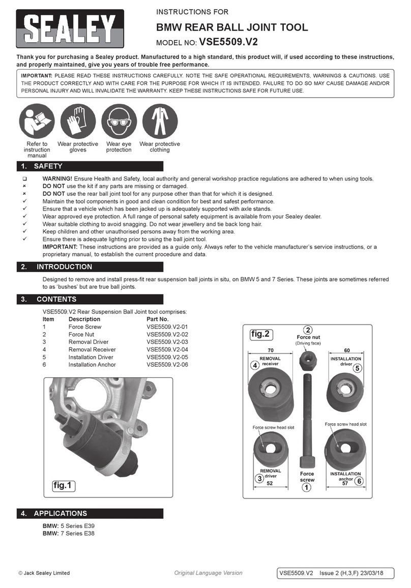
2.2 CONTENTS: UPPER STRUT SUPPORT
LOWER STRUT SUPPORT
ONE PAIR SMALL JAWS
ONE PAIR LARGE JAWS
SAFETY CHAINS AND ATTACHMENTS
2. INTRODUCTION & KIT CONTENTS
RE230UK - 1 - 060706
the strut assembly before removing it from the jaws of the
compressor.
POST OPERATIONAL SAFETY.
"When not in use, clean and store the spring compressor
in a safe, dry, childproof location.
"Maintain the spring compressor in good condition.
Replace or repair damaged parts. Use genuine parts only.
Unauthorised parts may be dangerous and will
invalidate the warranty.
RE230
CONVERTED
RE230
(ORIGINAL)
Fig.2
Fig.1
4.5 The converted unit must now be fixed securely to the ground in order to ensure the safety of the user.
Holes are to be found in the brackets, which allow the unit to be secured by way of masonry bolts or sinking pins into
concrete.
! WARNING! Whichever method is used, ensure the unit is adequately fixed and cannot topple.
4. CONVERTION PROCEDURE
4.1 First remove both strut support brackets from the existing unit.
UPPER BRACKET(Fig.3): Remove the ‘R’ clips ‘E’ & ‘G’ from the two long pins
which hold the bracket in place. Support the bracket and its adjustable jaws
and remove the two pins ‘D’ & ‘F’. Slide the bracket up and off the main pillar.
Retain the two clips and the two long pins for use with the new bracket.
LOWER BRACKET(Fig.4): The lower strut support bracket is attached to the
top of the ram with a grub screw which passes through a saddle mounted on
a pin in the back of the bracket. Remove the grub screw ‘Z’ and slide the
bracket up and off the main pillar.
4.2 The new lower strut support already has a pin mounted saddle fitted
within it. Slide the new lower strut support over the main pillar (see ‘X’ in
Fig.5) until the top of the ram passes into the saddle. Once you are sure
that the top of the ram has passed fully into the saddle tighten the grub
screw mounted in the side of the saddle (see ‘A’ in Fig.5).
4.3 Slide the new upper strut support ‘Y’ over the main pillar to the required
height and align the two holes in the support with two holes in the pillar.
Slide the two long pins (see D & F in Fig.6) through the assembly and
retain them in position using the ‘R’ clips (see E & G in Fig.6).
4.4 Two pairs of support jaws are supplied, one large pair and one small pair.
To fit either pair of jaws see Fig.7. Hold the chosen jaw in place within each
support bracket and slide the connecting pin ‘K’ back into place and retain it
with the ‘R’ clip. Replace the socket cap bolt ‘J’. The jaws are designed to be
used as matched pairs and should not be mixed.
Fig.5
Fig.6
Fig.7
5. INSTRUCTIONS FOR USE
5.1 Measure the outer diameter of the spring to be compressed and select the correct set of jaws. Fit the jaws as described in
para.4.4.
5.2 Operate the release valve pedal (fig.8-B) and press down on the lower strut support until the piston is full retracted.
5.3 The upper jaw should bear down on the first full coil down from the top of the strut. The lower jaw should be pushing up on
the first full coil up from the bottom of the strut. Measure the distance between these coils and adjust the position of the
upper strut support so that the distance between the jaws is slightly larger than required. Ensure that the pins fixing the upper
support are fully inserted and retained with the spring clips provided. Use the foot pedal (fig.8-A) to raise the lower jaw/strut
support to finely adjust the distance between the jaws.
5.4 Before commencing compression, make a visual inspection of machine to ensure pins are securely positioned and that there is
no sign of wear or fatigue – if found, do not use the unit and refer to your local Sealey dealer for advice and replacement parts.
5.5 Insert the strut into the jaws and ensure that the lower coil used lies behind the retaining rim at the back of the jaw. Operate
the foot pedal to raise the upper coil used into contact with the upper jaw ensuring once again that the coil is retained by
the raised rim within the jaw.
5.6 Wrap a safety chain around the portion of the spring and strut protruding from the upper jaw ensuring that the chain
lies above the jaw. Wrap another chain around the spring and strut protruding from the lower jaw ensuring that the
chain lies below the jaw. Fasten each chain behind the main pillar using the sprung catches attached. Make sure each
chain is as tight as possible. Do not position the chain between the coils held between the jaws.
5.7 When applying compression to the spring, always stand to one side of the unit and keep hands and fingers away from the
assembly during compession.
Fig.3
Fig.4
RE230UK - 1 - 060706
6. MAINTENANCE
6.1 Before each use, check the compressor to ensure it is not damaged or worn. If in any doubt DO NOT use the unit.
Remove it from service immediately and contact your local Sealey dealer for advice/repairs.
6.2 Refilling the hydraulic system with oil is rarely necessary but the level should be checked in the event of a loss of
performance. To check oil level, ensure the ram is fully lowered, remove filler plug and check that level is within 10mm of
filler hole. Add hydraulic jack oil if necessary.
NOTE:
Use a good quality jack oil, such as SEALEY HYDRAULIC JACK OIL.
!WARNING: DO NOT use brake fluid, or any fluid other than hydraulic jack oil as this will cause serious
damage to the jack and will invalidate the warranty!
Fig.8
Fig.9
Fig.10
We, the sole importer into the UK, declare that the products listed here are in conformity with the following
standards and directives.
For Jack Sealey Ltd. Sole importer into the UK of Sealey Professional Tools.
STRUT & SPRING COMPRESSING
STATIONS
Model: RE230 & RE231
98/37/EC Machinery Directive
93/68/EEC CE Marking Directive
18th January 2006
Signed by
Tim Thompson
7. DECLARATION OF CONFORMITY
The construction files for these products are held by the Manufacturer and may be inspected, by a national
authority, upon request to Jack Sealey Ltd.
5.8 Gradually compress the spring by pumping the foot pedal ensuring that the spring and strut remain securely held at all
times. Ensure that the strut and the body of the compressor are correctly aligned at all times during spring
compression. For conical springs, the centre line of the spring should remain parallel to the compressor body.
$
DANGER! Stop compressing the spring before the coil windings touch. You need only compress the spring until the
strut top plate is free from the spring.
5.9 Before attempting to remove top cap nut, always use a tool or short stick to test if the spring compression has been relieved from
the top plate. Do not use your hands / fingers. Sealey recommends the use of purpose made strut tools to remove the top-nut
from the shock absorber piston (SX300, SX301, SX302). Ensure that the shock absorber is supported as the top nut is undone
to prevent it falling down through the coils and causing injury.
5.10 Once compressed, and the strut removed, we recommend releasing the tension on the spring. Do not leave the spring
under compression in the machine unattended and do not leave in compression for prolonged periods i.e. overnight.
5.11 Allow the spring to gradually decompress by carefully operating the valve release pedal keeping your hands and fingers away
from the spring assembly.
5.12 Replace the spring or shock absorber as necessary and reassemble the strut by first compressing the spring and then
introducing the shock absorber up through the lower jaw and compressed spring coils. Re-attach the top plate and top
nut.
5.13 Before releasing the compression ensure that the top strut-nut is securely fastened to the maker’s tolerance.
5.14 Release the compression slowly keeping your hands and fingers away from the spring assembly.
5.15 Be sure that the tension on the spring is fully controlled by the strut assembly before removing it from the jaws of the
compressor and that the top cap is secured in the top windings of the spring.
A
B
C
UNCOMPRESSED
COMPRESSED
RE230UK - 1 - 060706
01284 757500
01284 703534 sales@sealey.co.uk
Sole UK Distributor
Sealey Group,
Bury St. Edmunds, Suffolk.
www.sealey.co.uk
Web
email

Other Sealey Service Equipment manuals

Sealey TP201 User manual

Sealey

Sealey TP201 User manual

Sealey VS8626 User manual

Sealey

Sealey VS8626 User manual

Sealey VS710 User manual

Sealey

Sealey VS710 User manual

Sealey RE012 User manual

Sealey

Sealey RE012 User manual

Sealey AK456DX User manual

Sealey

Sealey AK456DX User manual

Sealey AK36D.V2 User manual

Sealey

Sealey AK36D.V2 User manual

Sealey MS070.V2 User manual

Sealey

Sealey MS070.V2 User manual

Sealey AK467D User manual

Sealey

Sealey AK467D User manual

Sealey ES500.V2 User manual

Sealey

Sealey ES500.V2 User manual

Sealey TH003.V2 User manual

Sealey

Sealey TH003.V2 User manual

Sealey AK451DX User manual

Sealey

Sealey AK451DX User manual

Sealey WS680.V2 User manual

Sealey

Sealey WS680.V2 User manual

Sealey MS070CR User manual

Sealey

Sealey MS070CR User manual

Sealey AS15000 User manual

Sealey

Sealey AS15000 User manual

Sealey TD2525CS User manual

Sealey

Sealey TD2525CS User manual

Sealey VS0041 User manual

Sealey

Sealey VS0041 User manual

Sealey SMC30 User manual

Sealey

Sealey SMC30 User manual

Sealey GA44 User manual

Sealey

Sealey GA44 User manual

Sealey RE901 User manual

Sealey

Sealey RE901 User manual

Sealey AK449D User manual

Sealey

Sealey AK449D User manual

Sealey AK36D.V2 User manual

Sealey

Sealey AK36D.V2 User manual

Sealey VS2005.V2 User manual

Sealey

Sealey VS2005.V2 User manual

Sealey MS070CR User manual

Sealey

Sealey MS070CR User manual

Sealey ADT3 User manual

Sealey

Sealey ADT3 User manual

Popular Service Equipment manuals by other brands

Magneti Marelli ATF EXTRA PRO user manual

Magneti Marelli

Magneti Marelli ATF EXTRA PRO user manual

Hyundai Midtronics GRX-5100 instruction manual

Hyundai

Hyundai Midtronics GRX-5100 instruction manual

Tronair 01-1229-0011 Operation & service manual

Tronair

Tronair 01-1229-0011 Operation & service manual

ULTIMATE SPEED HG02236 Assembly and Safety Advice

ULTIMATE SPEED

ULTIMATE SPEED HG02236 Assembly and Safety Advice

CEMB DWA1000CWAS manual

CEMB

CEMB DWA1000CWAS manual

Invacare TDX SP Assembly, installation and operating instructions

Invacare

Invacare TDX SP Assembly, installation and operating instructions

MAHLE AIR-NEX 9310 quick start guide

MAHLE

MAHLE AIR-NEX 9310 quick start guide

Waeco ASC 6300 G operating manual

Waeco

Waeco ASC 6300 G operating manual

Reflex Fillcontrol Auto Series operating manual

Reflex

Reflex Fillcontrol Auto Series operating manual

Gree CE42-24/F owner's manual

Gree

Gree CE42-24/F owner's manual

MSW Motor Technics MSW-DA-21 user manual

MSW Motor Technics

MSW Motor Technics MSW-DA-21 user manual

Multipick MHP II instructions

Multipick

Multipick MHP II instructions

Zell AC1800 Operation manual

Zell

Zell AC1800 Operation manual

RFL C37.94 instruction data

RFL

RFL C37.94 instruction data

Kärcher IP 55 operating instructions

Kärcher

Kärcher IP 55 operating instructions

CMO SPRK.ALU instruction manual

CMO

CMO SPRK.ALU instruction manual

Lube1 PROGEAR XC Premium Use and maintenance manual

Lube1

Lube1 PROGEAR XC Premium Use and maintenance manual

Comco 523 Series Installation and operator's manual

Comco

Comco 523 Series Installation and operator's manual

manuals.online logo
manuals.online logoBrands
  • About & Mission
  • Contact us
  • Privacy Policy
  • Terms and Conditions

Copyright 2025 Manuals.Online. All Rights Reserved.