SEH Dongleserver myUTN-800 User manual

USB Dongleserver
myUTN-800
Quick Installation Guide
MHAB-QI-myUTN800
Version: 2.0 | 2018-02


Overview
This 'Quick Installation Guide' describes the hardware installation and initial
setup of the myUTN-800.
Table of contents 1.
Do you need assistance? Contact us!
Überblick
Dieser 'Quick Installation Guide' beschreibt die Hardware-Installation und
Inbetriebnahme des myUTN-800.
Inhaltsverzeichnis 19.
Benötigen Sie Hilfe? Kontaktieren Sie uns!
Monday to Thursday
Friday 8:00 a.m. to 4:45 p.m. and
8:00 a.m. to 3:15 p.m. (CET)
+49 (0)521 94226-44
suppor[email protected]
www.seh-technology.com
Montag–Donnerstag
Freitag 8:00–16:45 Uhr
8:00–15:15Uhr
+49 (0)521 94226-44
suppor[email protected]
www.seh.de


Quick Installation Guide [de] 1
Contents
General Information . . . . . . . . . . . . . . . . . . . . . . . . . . . . . . . . . . . . . . . . . . . . . . . . . .2
Purpose .....................................................................................................................................2
Scope of Supply .....................................................................................................................2
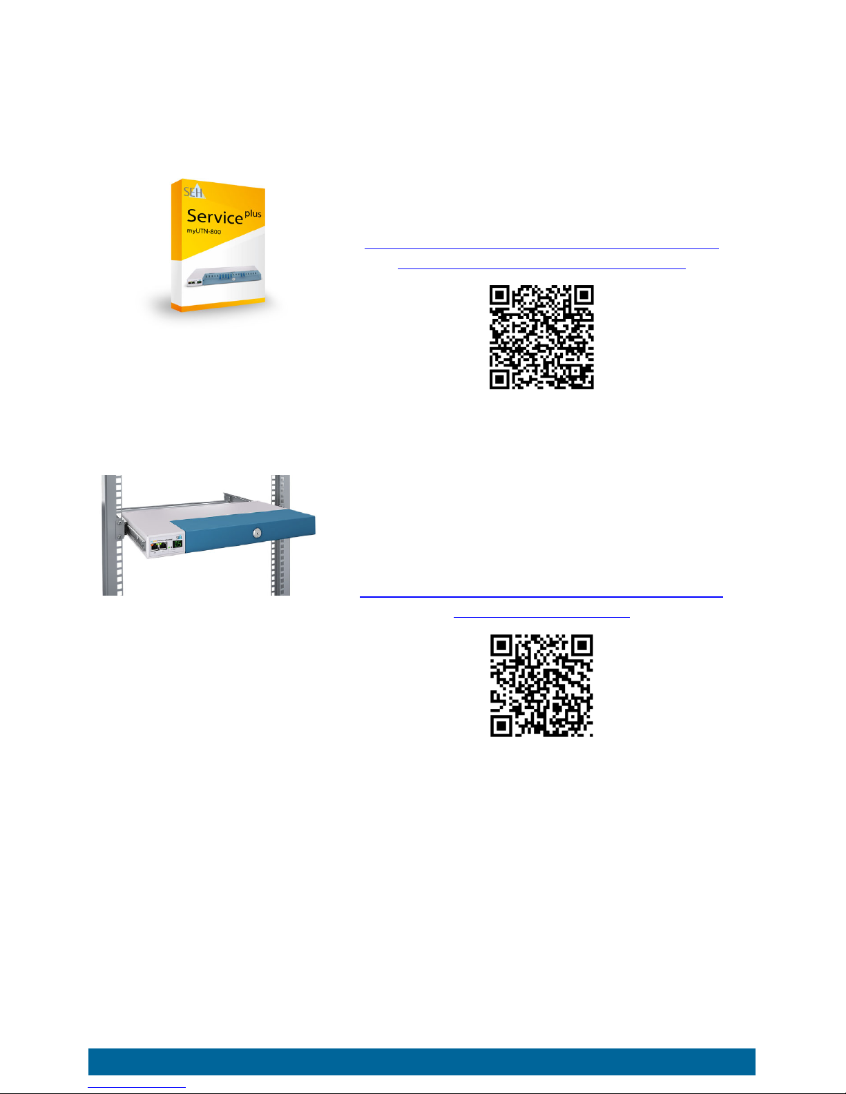
Accessories...............................................................................................................................3
Technical Data.........................................................................................................................4
LED Display ..............................................................................................................................5
Display Panel...........................................................................................................................5
Type Plate.................................................................................................................................6
Safety Regulations . . . . . . . . . . . . . . . . . . . . . . . . . . . . . . . . . . . . . . . . . . . . . . . . . . . .7
Hardware Installation . . . . . . . . . . . . . . . . . . . . . . . . . . . . . . . . . . . . . . . . . . . . . . . . .8
Software Installation. . . . . . . . . . . . . . . . . . . . . . . . . . . . . . . . . . . . . . . . . . . . . . . . . .9
Getting Started: SEH UTN Manager . . . . . . . . . . . . . . . . . . . . . . . . . . . . . . . . . . .10
Starting the SEH UTN Manager ......................................................................................10
Assigning an IP Address to the UTN Server................................................................12
Adding the UTN Server to the Selection List.............................................................13
Connecting the USB Dongle to the Client..................................................................14
Configuring the UTN Server . . . . . . . . . . . . . . . . . . . . . . . . . . . . . . . . . . . . . . . . . .15
Locking the UTN Server . . . . . . . . . . . . . . . . . . . . . . . . . . . . . . . . . . . . . . . . . . . . . .16
Mounting the UTN server in a rack . . . . . . . . . . . . . . . . . . . . . . . . . . . . . . . . . . . .17
Tools Required......................................................................................................................17
Prior to assembly .................................................................................................................17
Installation .............................................................................................................................18
Regulatory Compliance Information . . . . . . . . . . . . . . . . . . . . . . . . . . . . . . . . . .38

2 [de] Quick Installation Guide
General Information
Purpose
The Dongleserver 'myUTN-800' gives network participants access to USB
dongles. For this purpose, the USB dongles will be connected to the USB ports
of the myUTN-800. The software tool 'SEH UTN Manager' handles the access to
the USB dongles.
The SEH UTN Manager is installed on all clients that are intended to access a USB
dongle in the network. The SEH UTN Manager shows the availability of all UTN
servers in the network and establishes a connection between the client and the
USB port including the connected USB dongle.
The lockable housing cover of the myUTN-800 allows for a central and safe
storage of the USB dongles. The myUTN-800 itself can be mounted in a 19"
server rack.
The administration of the myUTN-800 is done via the 'myUTN Control Center'.
Scope of Supply
Check the package content before getting started:
UTN server Dongleserver 'myUTN-800'
Key For the lock in the dongle server lid
Quick
Installation
Guide
The Quick Installation Guide provides a brief
description of the installation of the myUTN-
800.
(This document)
2 power
cords Power supply cable
2 mounting
brackets 65.5 mm × 43 mm × 29.8 mm
4 screws M4 × 4 mm
SD card Inserted into SD card reader.

Quick Installation Guide [de] 3
Accessories
Value-adding accessories for your myUTN-800 are optionally available from SEH.
myUTN-800
Serviceplus Package The 'myUTN-800 Serviceplus package' extends the
manufacturer's guarantee of your myUTN-800
from 36 to 60 months. In addition, you will receive
quickly and easily an advance replacement device
in case of a defect!
Detailed information:
http://www.seh-technology.com/services/
service-packages/myutn-800.html
RMK3
(Rack Mount Kit Type 3) For a perfect and safe storage of your myUTN-800
we recommend the Rack Mount Kit 'RMK3'.
Using the Rack Mount Kit, you can mount the
myUTN-800 into 19" server racks. Contrary to the
mounting brackets included in delivery, the RMK3
allows for a comfortable access to the myUTN-800
via telescopic slides.
Detailed information:
http://www.seh-technology.com/products/
rack-mount-kits.html
s

4 [de] Quick Installation Guide
Technical Data
Properties Values
Network connection
logical:
physical: IEEE 802.3 (1000BaseT, 100BaseTX and 10BaseT)
2 × RJ-45 (STP Cat. 5)
Device connection • 20 × USB 2.0 Hi-Speed
• 1 × SD card reader
Current input • per connector approx. 45 mA at 100–240 VAC
without load
• per connector approx. 1.3 A at 100–240 VAC
with full load on the USB ports
Power consumption • max. approx. 6 W with full load on the USB ports
• typ. approx. 12 W with 20 USB dongles
• typ. approx. 105 kWh/year
Operating environment ambient temperature: 5–40 °C
relative humidity: 20–80%
Dimensions width: 422 mm
height: 44 mm
depth: 155 mm
(Suitable for 19" server racks.)
weight: 2950 g (with housing cover, without
mounting brackets)
activity LED
(yellow) status LED
(green)
USB ports 1–20
with LED for the USB port
reset button
201
restart button
SD card
reader
display panel
connector for
power supply 2
(at the rear side)
hole for strain-relief
cord grip (RMK3)
(at the rear side)
network
connector
(RJ-45)
12
connector for
power supply 1
(at the rear side)

Quick Installation Guide [de] 5
LED Display
The LEDs of the UTN server provide information about its status.
Display Panel
The display panel on the front of the UTN server provides status information.
LED Action Color Description
Activity flashes at
irregular
intervals
yellow Indicates the exchange of UTN data
packets.
Status permanently off
blinks 3 times
blinks 2 times
–
green
green
If the activity LED blinks periodically at
the same time, the BIOS mode is
signalized.
Indicates the assignment of a Zeroconf
IP address.
Indicates the assignment of an IP
address that does not correspond to
0.0.0.0 or that comes from outside the
Zeroconf range.
USB port
1–20 permanently off
permanently on
permanently on
–
green
orange
No USB dongle is connected to the
respective port.
A USB dongle is connected to the
respective port.
The connection to the respective port
and the attached USB dongle is
activated.
Important:
During the activation procedure, the behavior of the
LEDs differs from this description.
Text Description
DS (identifier)
The UTN server is operational.
RS The UTN server restarts.
DL Firmware/Software is being loaded onto the UTN server. Afterwards,
the update is carried out.

6 [de] Quick Installation Guide
Type Plate
The type plate gives important product information, such as hardware and
certification information as well as the serial number. The serial number
contains the production date: nnn YYYY MM nnnnn.
This information helps you e.g. during maintenance and is needed for support
requests as well as for the ’myUTN-800 Serviceplus Package’ 3.
E1 One of the two power supplies is not working.
Which connection is not working is indicated by a glowing dot (left
dot = left power supply; right dot = right power supply).
E2 The SD card is formatted with an unsupported file system
respectively cannot be read and be written to.
E3 The SD card is read-only.
E4 No SD card is available in the card reader.
E5 One or both network connections have no link.
Text Description

Quick Installation Guide [de] 7
Safety Regulations
UTN servers are network devices for use in office environments. The myUTN-800
is designed for the integration of USB dongles into TCP/IP networks.
• Read the documentation and make sure that your system meets the require-
ments listed therein.
• Avoid contact with humidity or liquids.
• The device must only be connected and operated if it is in perfect condition.
• Make sure that no-one steps on or stumbles over the cables.
• If the supplied power cords cannot be used in your country, acquire appro-
priate power cords that suit national provisions. For more information, con-
sult your retailer.
• The device must be connected to sockets with safety contact.
• Position the device in a way that guarantees that the sockets for the connec-
tion of the power cords are in the proximity of the device and are easily ac-
cessible. Make sure that the device can be separated easily from the mains.
Damaged power cords must be replaced immediately. For more information,
consult your retailer.
• Do not connect a telephone cable to the RJ-45 connectors. The RJ-45 con-
nectors may only be connected to SELV voltages. For the connection to the
RJ-45 connectors only STP cabling (category 5 or better) may be used. The
shielding must fit flushly to the connectors.
• Do not open the housing. Unauthorized modifications to the device can af-
fect the product certification and are forbidden.
• The device must not be directly connected to outdoor lines.
• Only use a certified USB cable (< 3 m) listed at www.usb.org.
• Electrostatic discharges (ESD) may impair device performance.
• An interruption of the supply voltage may impair device performance or
cause malfunctions.
Important:
Before starting the installation and the initial setup
procedure as well during the operation of the UTN
server, note the following safety regulations. Their
purpose is to protect yourself and others from personal
injuries, and to avoid damage to the equipment.

8 [de] Quick Installation Guide
Hardware Installation
You can directly connect up to 20 USB dongles to the myUTN-800.
1. Connect the USB dongle to a USB port of the UTN server.
2. Repeat step 1if you want to connect more than one USB dongle.)
3. Connect the network cable (RJ-45) to the UTN server.
4. Connect the power cord to the UTN server.
The UTN server boots and then is ready for use.
Important:
USB dongle and UTN server can be connected via a USB
cable, if required.
Only use USB cables shorter than 3 meters.
WARNING
Do not remove the SD card from the UTN server.
Important:
Upon delivery, the SD card is already inserted into the
SD card reader and ready for use.
Installation or formatting are not required.
USB dongles
myUTN-800
network
clients with software tool 'SEH UTN Manager'
USB 2.0

Quick Installation Guide [de] 9
Software Installation
The software tool ’SEH UTN Manager’ organizes the access of the USB dongles.
The SEH UTN Manager is available in two versions:
•Completeversion
• Minimal version (only command-line interface)
The complete version has a graphical user interface and offers additional
features. A detailed description can be found in the myUTN User Manual.
The SEH UTN Manager is installed on all clients that are intended to access a USB
dongle in the network. Different installation files are available, depending on
the operating system.
First, you have to download the installation file for the SEH UTN Manager from
the website of SEH Computertechnik GmbH:
http://www.seh-technology.com/services/downloads/
download-dongleserver/myutn-800.html
System requirements:
– Windows: XP or higher except for Windows Vista and Windows Server 20081;
OS X 10.8.x, OS X 10.9.x, OS X 10.10.x, OS X 10.11.2 and later2, or OS X 10.12.x
and later3
– The installation can only be carried out by users with administrative rights.
1. Start the installation file.
2. Install the complete version of the SEH UTN Manager (including graphical
user interface). To do so, follow the installation routine.
The SEH UTN Manager is installed on your client.
1. Windows 7 and Windows Server 2008 R2: KB3033929 (https://technet.microsoft.com/en-us/li-
brary/security/3033929) must be installed.
2. OS X 10.11.2 and later: limited USB device support
3. macOS 10.12.x and later: limited USB device support
Important:
The SEH UTN Manager is also available for selected
Linux systems.
All information necessary for installing and using the
SEH UTN Manager in Linux environments can be found
in the myUTN User Manual Linux. The documentation is
available via the link given above.

10 [de] Quick Installation Guide
Getting Started: SEH UTN Manager
After the SEH UTN Manager is started, the network will be scanned for
connected UTN servers. The network range to be scanned is freely definable.
All UTN servers found will be shown in the 'network list' together with the
connected USB dongles. The required UTN servers will be selected and added to
the 'selection list'. The UTN servers listed in the selection list and the connected
USB dongles can then be used by the user.
This chapter describes the first steps with the program.
• ’Starting the SEH UTN Manager’ 10
• ’Assigning an IP Address to the UTN Server’ 12
• ’Adding the UTN Server to the Selection List’ 13
• ’Connecting the USB Dongle to the Client’ 14
Detailed information on how to use the SEH UTN Manager can
be found in the Online Help. To start the online help, go to the
menu bar and select Help – Online Help.
Starting the SEH UTN Manager
Windows
Start the SEH UTN Manager on your client via the Windows start menu.
(Start All apps SEH Computertechnik GmbH SEH UTN Manager)
Important:
Client and UTN server communicate via the UTN port
9200. This port must not be blocked by a security
software (firewall). If necessary, you can change the port
number and use a secure UTN SSL port. A detailed
description can be found in the myUTN User Manual.

Quick Installation Guide [de] 11
Mac
To start the program, double-click the 'SEH UTN Manager.app' file.
(Applications SEH UTN Manager.app)
Important:
During the initial configuration, client and UTN server
must be assigned to the same local network segment.

12 [de] Quick Installation Guide
Assigning an IP Address to the UTN Server
Once the UTN server is connected to the network, it checks whether an IP
address can be obtained from the boot protocols BOOTP or DHCP. If this is not
the case, the UTN server assigns itself an IP address via Zeroconf from the
address range reserved for Zeroconf (169.254.0.0/16).
The UTN servers found by the program will be displayed in the network list. You
can change the TCP/IP parameters of the UTN server.
1. Confirm the note dialog Your Selection List seems to be empty with Yes.
If the note dialog is not available and the main dialog appears instead, select Selection List –
Edit in the menu bar.
The Edit Selection List dialog appears.
2. In the network list, select the UTN server.
3. In the shortcut menu, select Set IP Address.
The Set IP Address dialog appears.
4. Enter the relevant TCP/IP parameters.
5. Click OK.
The settings will be saved.

Quick Installation Guide [de] 13
Adding the UTN Server to the Selection List
The selection list displays the UTN servers and the USB dongles connected to
their USB ports.
Define the devices you want to use. To do this, you must add the UTN server
(and the connected USB dongles) shown in the network list to the selection list.
1. In the menu bar, select Selection List – Edit.
The Edit Selection List dialog appears.
2. In the network list, select the UTN server.
3. Click Add.
4. Repeat steps 2 to 3, if necessary.
5. Click OK.
The UTN servers are shown in the selection list.
You can extend the search for UTN servers to any network
range. To do this, change the search parameters for the net-
work scan.
Windows: Via Program – Options.
Mac: Via SEH UTN Manager – Preferences.

14 [de] Quick Installation Guide
Connecting the USB Dongle to the Client
To use a USB dongle, a connection is established between the client and the
USB port of the UTN server to which the USB dongle is connected.
All provisions (driver installation, etc.) necessary to operate the USB dongle
locally (i.e. connected directly to the client) have been met on the client. Ide-
ally, the USB dongle has been connected and operated on the client locally
according to the instructions of the manufacturer.
The USB port is not connected to another client. A USB dongle that was made
available by the UTN server can only be used by one network participant at a
time.
1. In the selection list, select the port.
2. From the menu bar, select Port – Activate.
The connection will be established.
Important:
Deactivate the connection to the USB port when you no
longer need the attached USB dongle. To do this, select
Port – Deactivate from the menu bar.

Quick Installation Guide [de] 15
Configuring the UTN Server
The UTN server can be configured and monitored via the 'myUTN Control
Center'. The myUTN Control Center is stored in the UTN server and can be
launched by means of a browser (Microsoft Edge, Firefox, Safari).
1. Open your browser.
2. Enter the IP address of the UTN server as the URL.
The myUTN Control Center appears in the browser.
If the myUTN Control Center is not displayed, check the proxy settings of your browser.
Detailed information about the configuration of the UTN
server can be found in the Online Help of the myUTN Control
Center.
To start the Online Help, click the '?' icon.

16 [de] Quick Installation Guide
Locking the UTN Server
The myUTN-800 has a lockable lid. With it, you can protect the USB dongles.
To close the Dongleserver, insert the two straps of the lid into the notches of the
housing. The key for the lock is delivered with the myUTN-800 2.
Other manuals for Dongleserver myUTN-800
2
Table of contents
Languages:
Other SEH Server manuals