SEH INU-100 Manual

USB Deviceserver
INU-100
Hardware Installation Guide
MHAB-EB-INU100
Version: 1.1 | 2017-04

Overview
This 'Hardware Installation Guide' provides a description of
the hardware installation of the INU-100. The initial setup is
described in the 'Quick Installation Guide'.
Table of contents 1.
Do you need assistance? Contact us!
Überblick
Dieser 'Hardware Installation Guide' beschreibt die Hardware-
Installation des INU-100. Die Inbetriebnahme wird im 'Quick
Installation Guide' erklärt.
Inhaltsverzeichnis 20.
Benötigen Sie Hilfe? Kontaktieren Sie uns!
Monday to Thursday
Friday 8:00 a.m. to 4:45 p.m. and
8:00 a.m. to 3:15 p.m. (CET)
+49 (0)521 94226-44
suppor[email protected]
www.seh-technology.com
Montag–Donnerstag
Freitag 8:00–16:45 Uhr
8:00–15:15Uhr
+49 (0)521 94226-44
suppor[email protected]
www.seh.de

Hardware Installation Guide [en] 1
Table of Contents
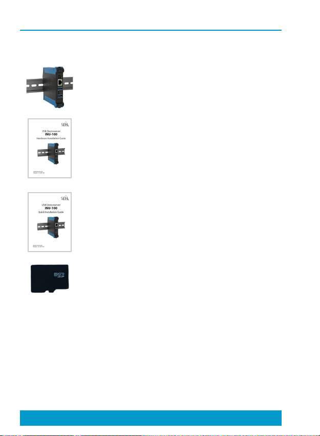
Scope of Supply . . . . . . . . . . . . . . . . . . . . . . . . . . . . . . . . . . . . . . 2
Technical Data. . . . . . . . . . . . . . . . . . . . . . . . . . . . . . . . . . . . . . . . 3
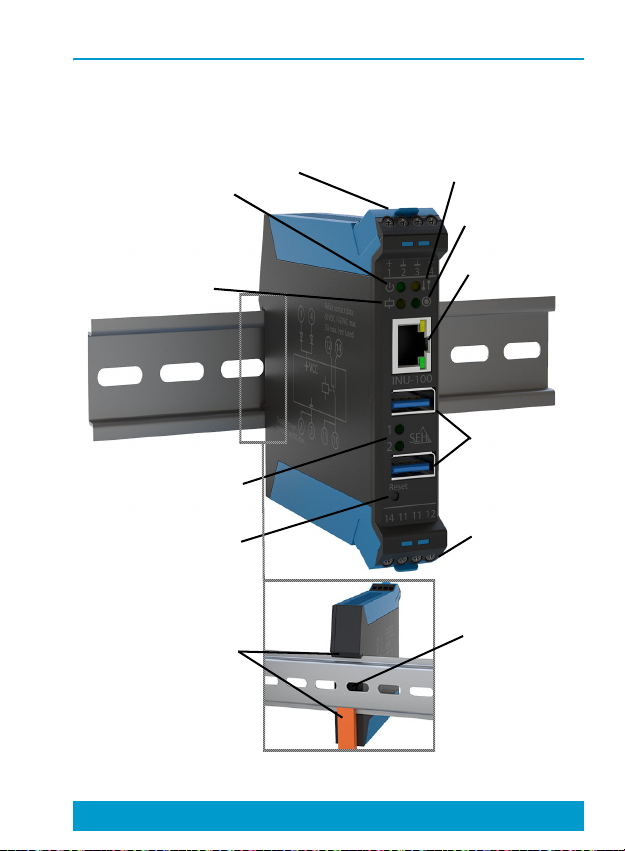
Device Overview............................................................................... 3
Dimensions & Weight...................................................................... 4
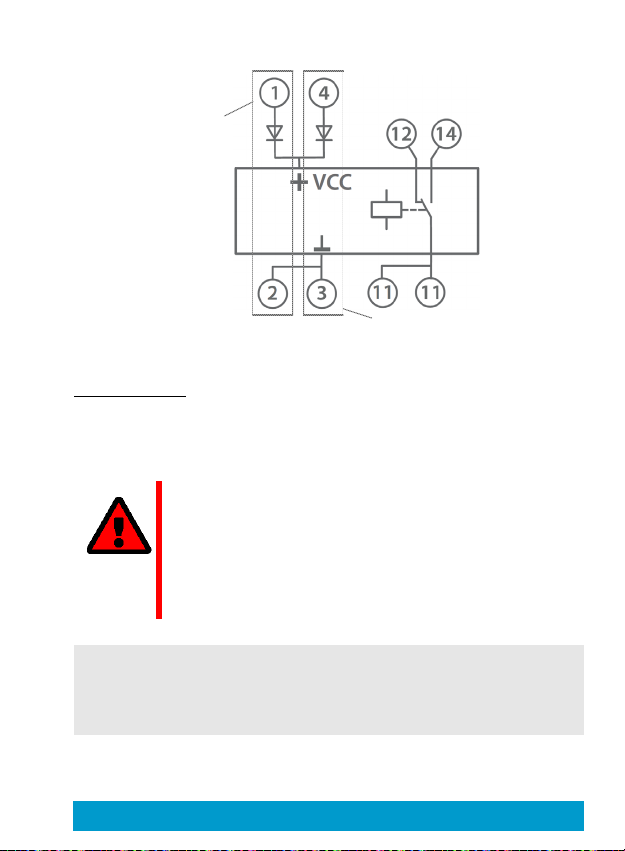
Connectors.......................................................................................... 5
Type Plate ............................................................................................ 7
LED Display . . . . . . . . . . . . . . . . . . . . . . . . . . . . . . . . . . . . . . . . . . 8
Safety Regulations . . . . . . . . . . . . . . . . . . . . . . . . . . . . . . . . . .10
Hardware Installation. . . . . . . . . . . . . . . . . . . . . . . . . . . . . . . .12
After the Hardware Installation. . . . . . . . . . . . . . . . . . . . . . .15
Regulatory Compliance Information . . . . . . . . . . . . . . . . . . 16
EC – Declaration of Conformity.................................................16
Federal Communication Commission (FCC) Notice...........18

2 [en] Hardware Installation Guide
Scope of Supply
Please check the package content before getting started:
INU server USB Deviceserver 'INU-100'
Hardware
Installation
Guide
The Hardware Installation
Guide provides a brief
description of the installation of
the INU-100.
(This document)
Quick
Installation
Guide
The Quick Installation Guide
provides a brief description of
the initial setup of the INU-100.
microSD
card Inserted into microSD card
reader.

Hardware Installation Guide [en] 3
Technical Data
Device Overview
reset button relay
connectors
USB port LEDs
network
connector
power LED
activity LED
status LED
relay LED
power connectors
USB ports
micro SD
card reader
snap lock

4 [en] Hardware Installation Guide
Dimensions & Weight
Properties Values
Network connection
logical:
physical:
IEEE 802.3 (1000BaseT, 100BaseTX
and 10BaseT)
1 × RJ-45
Device connection - 2 × USB 3.0 SuperSpeed
- 1 × microSD card reader
Operating
Environment - ambient temperature: 5–40 °C
- relative humidity: 20–80%
150 g
114 mm
105.5 mm
117.3 mm
117.3 mm
22.5 mm

Hardware Installation Guide [en] 5
Connectors
(You can find this circuit diagram on the INU server's side.)
Power supply
The INU server can be fed by 2 power supplies. While one
power supply is actively supplying, the other serves as
backup.
WARNING
The INU server and the power supply or power
supplies must be installed in the same control
cabinet. And the low-voltage cable between the
power supply or power supplies and the INU
server must not be longer than 3 m.
Power supply 1:
2:
connection:
Connectors 1 + 2
Connectors 3 + 4
via screw terminals
power supply 1
power supply 2
normally
closed normally
open

6 [en] Hardware Installation Guide
Relay
You can use the INU server's relay for various purposes in your
environment. For more information see the INU User Manual;
available at:
http://www.seh-technology.com/services/
downloads/industrial/inu-100.html
supply voltage - 12 V to 48 V DC with a capacity of
at least 15 W
-redundant
Current input at 12 V:
at 24 V:
- approx. 200 mA without load
- approx. 1200 mA with full load
on the USB ports
- approx. 110 mA without load
- approx. 550 mA with full load on
the USB ports
Cable
Required stripping:
Insertion: approx. 7 mm
stripped end with or without end
terminals
Type potential-free changeover switch
Contact data:
switching voltage:
switching current:
switching power:
max. 60 V DC or 42 V AC
max. 3 A
max. 180 VA for DC or max. 126 VA
for AC

Hardware Installation Guide [en] 7
Type Plate
The type plate gives important product information, such as
hardware and certification information as well as the serial
number. This information helps you e.g. during maintenance
and is needed for the guarantee extension.
Cable IEC:
UL:
Required stripping:
Insertion:
400 V / 0.2–2.5mm²
300 V / 10 A / AWG 26–AWG 12
approx. 7 mm
stripped end with or without end
terminals
Fuse none
The serial number contains the production date:
nnn YYYY MM nnnnn

8 [en] Hardware Installation Guide
LED Display
The LEDs of the INU server provide information about its
status.
LED Action Color Description
Power permanently
off
permanently
on
–
green
INU server is on.
INU server is off.
Activity blinks at
irregular
intervals
yellow Indicates the exchange
of network data packets.
Status permanently
off
blinks 3
times
blinks 2
times
–
green
green
If the activity LED blinks
periodically at the same
time, the BIOS mode is
signalized.
Indicates the assignment
of a Zeroconf IP address.
Indicates the assignment
of an IP address that does
not correspond to 0.0.0.0
or that comes from
outside the Zeroconf
range.

Hardware Installation Guide [en] 9
USB
ports
1–2
permanently
off
permanently
on
permanently
on
–
green
orange
No USB device is
connected to the
respective port.
A USB device is
connected to the
respective port.
The connection to the
respective port and the
attached USB device is
activated.
Relay permanently
off
permanently
on
–
yellow
Default state (normally
open is open).
Switched (normally open
is closed).
LED Action Color Description

10 [en] Hardware Installation Guide
Safety Regulations
INU servers are network devices for use in industrial
environments. The INU-100 is designed for the integration of
USB devices into TCP/IP networks.
• Read the documentation and make sure that your system
meets the requirements listed therein.
• The device must only be connected to the mains and to
the network by qualified personnel.
• Avoid contact with humidity or liquids.
• The device must only be connected and operated if it is in
perfect condition.
• Do not connect a telephone cable to the RJ-45 connector.
The RJ-45 connector may only be connected to SELV volt-
ages. For the connection to the RJ-45 connector only STP
cabling (category 5 or better) may be used. The shielding
must fit flushly to the connector.
• Do not open the housing. Unauthorized modifications to
the device can affect the product certification and are for-
bidden.
• Only use a certified USB cable (< 3 m) listed at
www.usb.org.
• The device and the power supply or power supplies must
Important:
Before starting the installation and the initial
setup procedure as well during the operation of
the INU server, please note the following safety
regulations. Their purpose is to protect yourself
and others from personal injuries, and avoid
damage to the equipment.

Hardware Installation Guide [en] 11
be installed in the same control cabinet.
• The low-voltage cable between the power supply and the
device must not be longer than 3 m.
• The maximum load for the relay contacts is 60 V for DC /
42 V for AC and a current of max. 3 A.
• Choose cables with a suitable wire cross-section for the
connection to power supply and relay.

12 [en] Hardware Installation Guide
Hardware Installation
Install the INU-100 on a top-hat rail (DIN rail according to DIN
EN 60715, 35 mm wide). You can directly connect up to two
USB devices to the INU-100. In addition, you can connect a
load to the relay.
1. Install the INU server on a top-hat rail:
network
USB devices
relay output
power 1
power 2
INU-100
clients

14 [en] Hardware Installation Guide
4. Connect the network cable (RJ-45) to the INU server.
5. Connect the USB devices to the USB ports of the INU server:

Hardware Installation Guide [en] 15
Important:
Upon delivery, the microSD card is already
inserted into the microSD card reader and ready
for use (installation or formatting are not
required).

16 [en] Hardware Installation Guide
After the Hardware Installation
As soon as the hardware has been installed, the INU server
can be set up for operation. All information on how to do this
you will find in the enclosed document 'Quick Installation
Guide'.

Hardware Installation Guide [en] 17
Regulatory Compliance Information
EC – Declaration of Conformity
Manufacturer's name and address:
SEH Computertechnik GmbH
Suedring 11, 33647 Bielefeld, Germany
Phone: +49 (0)521 94226-0
Herewith SEH Computertechnik GmbH declares that
Product: USB Deviceserver
Type designation: INU-100
Serial no.: 287 yyyy mm nnnnn
(yyyy = year, mm = month, nnnnn = seq.
no.)
is in conformity with the provision of the
DIRECTIVE 2014/30/EU OF THE EUROPEAN PARLIAMENT
AND OF THE COUNCIL of 26 February 2014
on the harmonisation of the laws of the Member States
relating to electromagnetic compatibility (recast)
DIRECTIVE 2011/65/EU OF THE EUROPEAN PARLIAMENT
AND OF THE COUNCIL of 8 June 2011
on the restriction of the use of certain hazardous substances
in electrical and electronic equipment (recast)
Standards applied:
EN 55024:2010 + A1:2015
EN 55032:2012 Class B
EN61000-6-2:2005
EN 50581:2012
To meet the above specifications, the user has to comply with
all instructions defined in the enclosed manual Hardware
Installation Guide.
Other manuals for INU-100
2
Table of contents
Languages:
Other SEH Server manuals