SEH myUTN-250 User manual

Quick Installation Guide 1
Monday - Thursday
Friday
8:00 a.m. to 4:45 p.m. and
8:00 a.m. to 3:15 p.m. (CET)
℡+49 (0)521 94226-44
USB Deviceserver
myUTN-250
Quick Installation Guide
Overview [en]
This Quick Installation Guide provides
a description of the installation of the
myUTN-250. It contains the following
information:
General Information
Safety Regulations
Hardware Installation
Software Installation
Getting Started
Configuring the UTN Server
Please note the table of contents on
page 3. Should you have any further
questions, please contact our support
hotline.
Überblick [de]
Dieser Quick Installation Guide
beinhaltet eine Beschreibung der
Installation des myUTN-250. Sie
erhalten die folgenden Informationen:
Allgemeine Information
Sicherheitsvorschriften
Hardware-Installation
Software-Installation
Erste Schritte
UTN-Server konfigurieren
Beachten Sie das Inhaltsverzeichnis
auf Seite 17. Falls Sie noch Fragen
haben, kontaktieren Sie unsere
Support- Hotline.

2 Quick Installation Guide
Date of Manufacture
The serial number includes the date of manufacture.
The serial number can be found on the type plate.

Quick Installation Guide [en] 3
2 General Information . . . . . . . . . . . . . . . . . . . . . . . . . . . . . . 4
Purpose . . . . . . . . . . . . . . . . . . . . . . . . . . . . . . . . . . . . . . . . . . . . . . . . . . 4
Scope of Supply . . . . . . . . . . . . . . . . . . . . . . . . . . . . . . . . . . . . . . . . . . 4
Technical Data . . . . . . . . . . . . . . . . . . . . . . . . . . . . . . . . . . . . . . . . . . . 5
LED Display . . . . . . . . . . . . . . . . . . . . . . . . . . . . . . . . . . . . . . . . . . . . . . 6
2 Safety Regulations . . . . . . . . . . . . . . . . . . . . . . . . . . . . . . . 7
2 Hardware Installation. . . . . . . . . . . . . . . . . . . . . . . . . . . . . 8
2 Software Installation . . . . . . . . . . . . . . . . . . . . . . . . . . . . . 9
2 Getting Started: SEH UTN Manager . . . . . . . . . . . . . . . 10
Starting the SEH UTN Manager . . . . . . . . . . . . . . . . . . . . . . . . . . .11
Assigning an IP Address to the UTN Server . . . . . . . . . . . . . . .12
Adding the UTN Server to the Selection List . . . . . . . . . . . . . .13
Connecting the USB Device to the Client . . . . . . . . . . . . . . . . .14
2 Configuring the UTN Server . . . . . . . . . . . . . . . . . . . . . . 15
Table of Contents

4 [en] Quick Installation Guide
General Information
Purpose
The USB Deviceserver 'myUTN-250' allows you to access non-network-ready USB
devices (e.g. hard disks, etc.) in the network. For this purpose, the USB devices will
be connected to the USB ports of the myUTN-250. The software tool 'SEH UTN
Manager' handles the access to the USB devices.
The SEH UTN Manager is installed on all clients that are intended to access a USB
device in the network. The SEH UTN Manager shows the availability of all UTN
servers in the network and establishes a connection between the client and the
USB port including the connected USB device.
The administration of the myUTN-250 is done via the 'myUTN Control Center'.
Scope of Supply
Please check the package content before getting started:
UTN server USB Deviceserver 'myUTN-250'
Quick
Installation
Guide
The Quick Installation Guide provides a brief
description of the installation of the myUTN-250.
(This document)
Power pack External power pack

Quick Installation Guide [en] 5
Technical Data
Properties Values
Network connection logical:
physical: - IEEE 802.3
-RJ-45
Device connection - 1 × USB 3.0 SuperSpeed
- 2 × USB 2.0 Hi-Speed
Current input - 350 mA @ 12 VDC (without load)
- 1350 mA @ 12 VDC (with full load on the USB ports)
Operating environment - Ambient temperature: 5–40 °C
- Relative humidity: 20–80%
Dimensions - Width: 140 mm
- Height: 32 mm
- Depth: 99 mm
- Weight: 50 g
1) Link LED (green)
2) Activity LED (yellow)
3) Status LED (green)
4) Power LED (yellow)
5) LED for the USB ports 1–3 (green/
orange)
6) Network connector (RJ-45) for
1000BaseT, 100BaseTX and 10BaseT
7) USB ports 1–3
(USB port 1: USB 3.0 SuperSpeed,
(USB ports 2 and 3: USB 2.0 Hi-Speed)
8) Reset button
9) Connector for the included power pack
Front view
Rear view

6 [en] Quick Installation Guide
LED Display
The LEDs of the UTN server provide information about its status.
LED Action Color Description
Link permanently on
permanently off
green
-
There is a connection to the network.
There is no connection to the network.
Activity blinks at irregular
intervals yellow Indicates the exchange of network data
packets.
Status permanently off
blinks 3 times
blinks 2 times
-
green
green
If the activity LED blinks periodically at the
same time, the BIOS mode is signalized.
Indicates the assignment of a ZeroConfig IP
address.
Indicates the assignment of an IP address that
does not correspond to 0.0.0.0 or that comes
from outside the ZeroConf range.
Power permanently on
permanently off
yellow
-
The device is powered.
The device is not powered.
USB ports 1–3 permanently off
permanently on
permanently on
-
green
orange
No USB device is connected to the respective
port.
A USB device is connected to the respective
port.
The connection to the respective port and the
attached USB device is activated.

Quick Installation Guide [en] 7
Safety Regulations
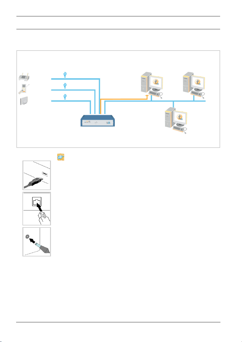
UTN servers are network devices for use in office environments. The myUTN-250
is designed for the integration of USB devices into TCP/IP networks.
Before starting the initial setup procedure and during the operation of the UTN
server, please note the following safety regulations. Their purpose is to protect
yourself and others from personal injuries, and avoid damage to the equipment.
Read the documentation and make sure that your system meets the
requirements listed therein.
Avoid contact with humidity or liquids.
The device must only be connected and operated if it is in perfect condition.
Make sure that no-one steps on or stumbles over the cables.
If the supplied power cord cannot be used in your country, acquire an
appropriate power cord that suits national provisions. For more information,
please consult your retailer.
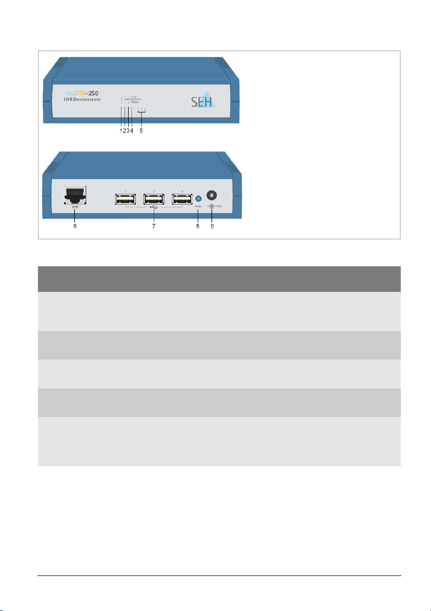
Do not connect a telephone cable to the RJ-45 connector. The RJ-45
connector may only be connected to SELV voltages. For the connection to the
RJ-45 connector only STP cabling (category 5 or better) may be used. The
shielding must fit flushly to the connector.
The device must only be operated using the power pack included in the
package.
Only use a certified USB cable (< 3 m) listed at www.usb.org.

8 [en] Quick Installation Guide
Hardware Installation
You can directly connect up to three USB devices to the UTN server (myUTN-250).
network
clients with the software tool 'SEH UTN Manager'
myUTN-250
USB device
USB device
USB device
USB 3.0
USB 2.0
USB 2.0
Proceed as follows:
1. Connect the UTN server and the USB device to the USB data
cable. (Repeat this step if you want to connect more than
one USB device.)
2. Connect the network cable (RJ-45) to the UTN server.
3. Connect the power cord to the UTN server.

Quick Installation Guide [en] 9
Software Installation
The software tool SEH UTN Manager organizes the access to the USB devices. The
SEH UTN Manager is available in two versions:
Complete version
Minimal version (only command-line interface)
The complete version has a graphical user interface and offers additional
features. A detailed description can be found in the myUTN User Manual.
The SEH UTN Manager is installed on all clients that are intended to access a USB
device in the network. Different installation files are available, depending on the
operating system.
First, you have to download the installation file for the SEH UTN Manager from
the homepage of SEH Computertechnik GmbH:
http://www.seh-technology.com/products/usb-device-servers/
products/myutn-250-downloads.html
Scan this QR code using your smart phone to get direct access to the homepage.
System requirements:
- Windows XP or later;
Mac OS X 10.6.x, Mac OS X 10.7.x (64-bit), OS X 10.8.x, 10.9.x
- The installation can only be carried out by users with administrative rights.
Proceed as follows:
1. Start the installation file.
2. Install the complete version of the SEH UTN Manager (including graphical
user interface). Follow the installation routine.
The SEH UTN Manager is installed on your client.

10 [en] Quick Installation Guide
Getting Started: SEH UTN Manager
After the SEH UTN Manager is started, the network will be scanned for connected
UTN servers. The network range to be scanned is freely definable.
All UTN servers found will be shown in the 'network list' together with the
connected USB devices. The required UTN servers will be selected and added to
the 'selection list'. The UTN servers listed in the selection list and the connected
USB devices can then be used by the user.
This chapter describes the first steps with the program.
’Starting the SEH UTN Manager’ 11
’Assigning an IP Address to the UTN Server’ 12
’Adding the UTN Server to the Selection List’ 13
’Connecting the USB Device to the Client’ 14
Client and UTN server communicate via the UTN port 9200. This port must not be
blocked by a firewall. If necessary, you can change the port number and use a
secure UTN SSL port. A detailed description can be found in the myUTN User Manual.
Detailed information on how to use the SEH UTN Manager can
be found in the Online Help. To start the Online Help, select
Help – Online Help from the menu bar.

Quick Installation Guide [en] 11
Starting the SEH UTN Manager
Windows
Start the SEH UTN Manager on your client via the Windows start menu.
(Start
J
All Programs
J
SEH Computertechnik GmbH
J
SEH UTN Manager)
In some cases the Windows user account control requires a confirmation if the
SEH UTN Manager is to be run.
Mac
To start the program, double-click the 'SEH UTN Manager.app' file.
(Applications JSEH UTN Manager.app)
During the initial configuration, client and UTN server must be assigned to the
same local network segment.

12 [en] Quick Installation Guide
Assigning an IP Address to the UTN Server
Once the UTN server is connected to the network, it checks whether an IP address
can be obtained from the boot protocols BOOTP or DHCP. If this is not the case,
the UTN server assigns itself an IP address via ZeroConf from the address range
(169.254.0.0/16) which is reserved for ZeroConf.
The UTN servers found by the program will be displayed in the network list. You
can change the TCP/IP parameters of the UTN server.
Proceed as follows:
1. Confirm the note dialog 'Your Selection List seems to be empty' by clicking
Yes.
If no note dialog is available and the main dialog appears, select Selection List – Edit
from the menu bar.
The Edit Selection List dialog appears.
2. Select the UTN server from the network list.
3. Select Set IP Address from the shortcut menu.
The Set IP Address dialog appears.
4. Enter the relevant TCP/IP parameters.
5. Click OK.
The settings are saved.

Quick Installation Guide [en] 13
Adding the UTN Server to the Selection List
The selection list displays the UTN servers and the USB devices connected to their
USB ports.
Define the devices you want to use. To do this, you must add the UTN server (and
the connected USB devices) shown in the network list to the selection list.
Proceed as follows:
1. Select Selection List – Edit from the menu bar.
The Edit Selection List dialog appears.
2. Select the UTN server from the network list.
3. Click Add.
(Repeat steps 2 and 3, if necessary.)
4. Click OK.
The UTN servers are shown in the selection list.
You can extend the search for UTN servers to any network range. To do this,
change the search parameters for the network scan.
Windows: via the Options dialog in the Program menu.
Mac: via the Preferences dialog in the SEH UTN Manager menu.

14 [en] Quick Installation Guide
Connecting the USB Device to the Client
To use a USB device, a connection is established between the client and the USB
port of the UTN server to which the USB device is connected.
Make sure that:
- All provisions (driver installation, etc.) necessary to operate the USB device
locally (i.e. connected directly to the client) have been met on the client.
Ideally, the USB device has been connected and operated on the client locally
according to the instructions of the manufacturer.
- The USB port is not connected to another client. A USB device that was made
available by the UTN server can only be used by one network participant at a
time.
Proceed as follows:
1. Select the port from the selection list.
2. Select Port – Activate from the menu bar.
The connection will be established.
Close the connection to the USB port when the connected USB device is no
longer needed. Select Port - Deactivate from the menu bar.

Quick Installation Guide [en] 15
Configuring the UTN Server
The UTN server can be configured and monitored via the myUTN Control Center.
The myUTN Control Center is stored in the UTN server and can be launched by
means of a browser (Internet Explorer, Mozila Firefox, Safari).
Proceed as follows:
1. Open your browser.
2. Enter the IP address of the UTN server as the URL.
3. The myUTN Control Center appears in the browser.
If the myUTN Control Center is not displayed, check the proxy settings of your browser.
Detailed information about the configuration of the UTN server
can be found in the Online Help of the myUTN Control Center.
To start the Online Help, click the '?' icon.

16 [en] Quick Installation Guide

Quick Installation Guide [de] 17
2 Allgemeine Information . . . . . . . . . . . . . . . . . . . . . . . . . 18
Verwendungszweck . . . . . . . . . . . . . . . . . . . . . . . . . . . . . . . . . . . . .18
Lieferumfang. . . . . . . . . . . . . . . . . . . . . . . . . . . . . . . . . . . . . . . . . . . .18
Technische Daten . . . . . . . . . . . . . . . . . . . . . . . . . . . . . . . . . . . . . . .19
LED-Anzeige . . . . . . . . . . . . . . . . . . . . . . . . . . . . . . . . . . . . . . . . . . . .20
2 Sicherheitsvorschriften . . . . . . . . . . . . . . . . . . . . . . . . . . 21
2 Hardware-Installation . . . . . . . . . . . . . . . . . . . . . . . . . . . 22
2 Software-Installation . . . . . . . . . . . . . . . . . . . . . . . . . . . . 23
2 Erste Schritte mit dem SEH UTN Manager . . . . . . . . . 24
SEH UTN Manager starten. . . . . . . . . . . . . . . . . . . . . . . . . . . . . . . .25
UTN-Server eine IP-Adresse zuweisen . . . . . . . . . . . . . . . . . . . .26
UTN-Server der Auswahlliste hinzufügen . . . . . . . . . . . . . . . . .27
USB-Gerät mit Client verbinden . . . . . . . . . . . . . . . . . . . . . . . . . .28
2 UTN-Server konfigurieren. . . . . . . . . . . . . . . . . . . . . . . . 29
Inhaltsverzeichnis

18 [de] Quick Installation Guide
Allgemeine Information
Verwendungszweck
Der USB Deviceserver 'myUTN-250' erlaubt das Bereitstellen von nicht-
netzwerkfähigen USB-Geräten (z.B. Festplatten usw.) für mehrere
Netzwerkteilnehmer. Dazu werden die USB-Geräte an die USB-Ports des
myUTN-250 angeschlossen. Die Zugriffsverteilung der USB-Geräte erfolgt über
das Software-Tool 'SEH UTN Manager'.
Der SEH UTN Manager wird auf allen Clients installiert, die auf ein im Netzwerk
bereitgestelltes USB-Gerät zugreifen sollen. Der SEH UTN Manager zeigt die
Verfügbarkeit aller im Netzwerk eingebundenen UTN-Server an und stellt die
Verbindung zwischen Client und USB-Port inklusive dem daran angeschlossenen
USB-Gerät her.
Die Verwaltung des myUTN-250 erfolgt über das 'myUTN Control Center'.
Lieferumfang
Bitte überprüfen Sie den Packungsinhalt auf Vollständigkeit, bevor Sie die
Installation beginnen:
UTN-Server USB Deviceserver 'myUTN-250'
Quick
Installation
Guide
Der Quick Installation Guide beinhaltet eine kurze
Beschreibung der Installation des myUTN-250.
(Dieses Dokument)
Netzteil Externes Netzteil

Quick Installation Guide [de] 19
Technische Daten
Eigenschaften Werte
Netzwerkanschluss Logisch:
Physisch: - IEEE 802.3
-RJ-45
Geräteanschluss - 1 × USB 3.0 SuperSpeed
- 2 × USB 2.0 Hi-Speed
Stromaufnahme - 350 mA bei 12 VDC (ohne Last)
- 1350 mA bei 12 VDC (bei Volllast auf den USB-Ports)
Betriebsumgebung - Umgebungstemperatur: 5–40 °C
- Relative Luftfeuchtigkeit: 20–80%
Abmessungen - Breite: 140 mm
- Höhe: 32 mm
- Tiefe: 99 mm
- Gewicht: 150 g
1) Link-LED (grün)
2) Activity-LED (gelb)
3) Status-LED (grün)
4) Power-LED (gelb)
5) LED für die USB-Ports 1–3 (grün/
orange)
6) Netzwerkanschluss (RJ-45) für
1000BaseT, 100BaseTX und 10BaseT
7) USB-Ports 1–3
(USB-Port 1: USB 3.0 SuperSpeed,
(USB-Port 2 und 3: USB 2.0 Hi-Speed)
8) Reset-Taster
9) Anschluss für die Stromversorgung
über das mitgelieferte Netzteil
Vorderansicht
Rückansicht

20 [de] Quick Installation Guide
LED-Anzeige
Durch die Interpretation des LED-Leuchtverhaltens kann der Zustand des UTN-
Servers ermittelt werden.
LED Aktion Farbe Beschreibung
Link Dauer-An
Dauer-Aus
grün
-
Eine Verbindung zum Netzwerk ist vorhanden.
Es besteht keine Verbindung zum Netzwerk.
Activity unregelmäßiges
Blinken gelb Signalisiert den Austausch von Netzwerk-
Datenpaketen.
Status Dauer-Aus
3 x Blinken
2 x Blinken
-
grün
grün
Bei gleichzeitigem zyklischen Blinken der
Activity-LED wird der BIOS-Modus signalisiert.
Signalisiert die Vergabe einer ZeroConfig-IP-
Adresse.
Signalisiert die Vergabe einer IP-Adresse, die
nicht 0.0.0.0 entspricht oder aus dem Bereich
ZeroConfig kommt.
Power Dauer-An
Dauer-Aus
gelb
-
Das Gerät wird mit Strom versorgt.
Das Gerät wird nicht mit Strom versorgt.
USB-Port 1–3 Dauer-Aus
Dauer-An
Dauer-An
-
grün
orange
Es ist kein USB-Gerät am betreffenden Port
angeschlossen.
Es ist ein USB-Gerät am betreffenden Port
angeschlossen.
Die Verbindung zum betreffenden Port und
dem angeschlossenen USB-Gerät ist aktiviert.
Table of contents
Languages:
Other SEH Server manuals

SEH
SEH Dongleserver myUTN-800 User manual

SEH
SEH myUTN-50a User manual

SEH
SEH myUTN-50a User manual

SEH
SEH myUTN-50a User manual

SEH
SEH myUTN-80 User manual

SEH
SEH Mac OS 8 User manual

SEH
SEH myUTN-50a User manual

SEH
SEH myUTN-120 User manual

SEH
SEH myUTN-50 User manual

SEH
SEH Dongleserver myUTN-800 User manual
Popular Server manuals by other brands

Solarflare
Solarflare Solarflare XtremeScale series user guide

Dell
Dell PowerEdge XR8620t Installation and service manual

Austin Hughes Electronics
Austin Hughes Electronics RC-1000 Specifications

Dell
Dell PowerEdge 6350 Rack installation

Avaya
Avaya S8500 Series Installing and configuring

Lantech
Lantech IDS-2102A user manual