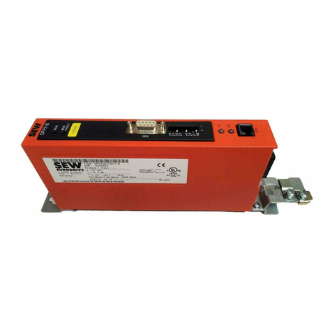
Manual – Fieldbus Interface INTERBUS UFI11A
3
1 Overview of the System.................................................................................... 4
2 Unit Structure .................................................................................................... 5
2.1 Front view .................................................................................................5
3 Installation and Operation with Autosetup..................................................... 6
3.1 Installation notes....................................................................................... 6
3.2 Setting the inverter parameters...............................................................10
3.3 Autosetup................................................................................................10
3.4 Configuring the fieldbus master .............................................................. 11
3.5 Starting the inverters...............................................................................12
4 Installation and Operation with a PC............................................................. 13
4.1 Installation notes..................................................................................... 13
4.2 PC connection.........................................................................................17
4.3 Setting the inverter parameters...............................................................17
4.4 Startup software......................................................................................17
4.5 Configuring the fieldbus master .............................................................. 18
4.6 Starting the inverters...............................................................................19
5 INTERBUS Interface........................................................................................20
5.1 Startup of the INTERBUS master ...........................................................20
5.2 Configuring the INTERBUS interface......................................................28
5.3 Examples of DIP switch settings for process data and
PCP communication in Autosetup mode.................................................31
5.4 Control via INTERBUS............................................................................34
5.5 PCP interface..........................................................................................35
5.6 Return codes for parameter setting.........................................................44
5.7 Autosetup................................................................................................46
6 Error Response ...............................................................................................48
6.1 Fieldbus timeout......................................................................................48
6.2 SBus timeout...........................................................................................48
6.3 Unit errors ...............................................................................................48
7 Diagnostic LEDs..............................................................................................49
7.1 States of the LEDs UL, RC, BA, TR and RD...........................................49
8 DIP Switches.................................................................................................... 51
9 Application examples ..................................................................................... 52
9.1 Control via process data ......................................................................... 52
9.2 Parameter setting via the PCP interface.................................................52
9.3 Representation of the coding examples..................................................53
9.4 Sequence of a parameter setting process ..............................................53
9.5 Reading of an UFI parameter..................................................................54
9.6 Writing of UFI11A or drive parameters via object 8288 .......................... 55
9.7 Reading of UFI11A or drive parameters via object 8288........................56
10 Parameter List ................................................................................................. 58
11 List of Errors.................................................................................................... 59
12 Technical Data................................................................................................. 61
13 Dimensions......................................................................................................62
14 Index.................................................................................................................63
