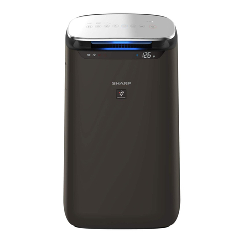
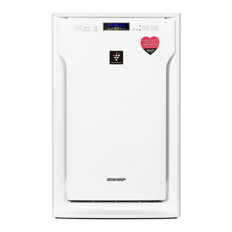
Sharp FU-40SE-TA User manual

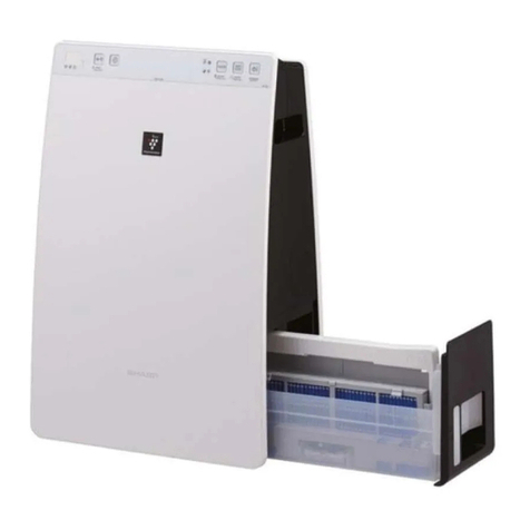
FU-40SE-TA
SERVICE MANUAL
SHARP CORPORATION
S4318FU40SETA
AIR PURIFIER
In the interests of user-safety (Required by safety regulations in some
countries) the set should be restored to its original condition and only
parts identical to those specified should be used.
FU-40SE-TA
MODEL
Page
SAFETY PRECAUTIONS ..................................................................................................................................2
FOR EFFECTIVELY USING THIS PRODUCT..................................................................................................4
SPECIFICATIONS .............................................................................................................................................4
NAMES OF PARTS .......................................................................................................................................... 5
INSTALLATION .................................................................................................................................................6
OPERATION......................................................................................................................................................8
WIRING DIAGRAM......................................................................................................................................... 10
TROUBLESHOOTING GUIDE ........................................................................................................................20
REPLACEMENT OF MAIN PARTS .................................................................................................................22
CARE AND MAINTENANCE .......................................................................................................................... 25
USE RESIN TABLE .........................................................................................................................................26
PARTS LIST ....................................................................................................................................................26
TABLE OF CONTENTS
Tabletop / wall-mounting type

2
FU-40SE-TA
SAFETY PRECAUTIONS
•
Do not use the unit if the power cord or plug is damaged or the connection to the wa
ll
outlet is loose.
Electrical shock, short circuit and/or fire may occur as a result.
•
Do not damage,break,coat,forcefully bend,pull, twist,bundle,pinch or place heavyobjec
ts
on the power cord.
If the power cord is damaged, fire and/or electrical shock may occur as a result.
•
Use AC 220 - 240V only.
Fire and/or electrical shock may occur as a result.
•
Do not modify. Repair and disassembly of this product are to be performed by authorize
d
service personnel only.
Fire, electrical shock and/or bodily injury may occur as a result.
For repair, contact your dealer of purchase or the nearest Sharp Service Center.
•
Periodically remove dust from the power plug
Accumulated dust on the power plug may cause bad insulation from humidity, etc.
Fire and/or electrical shock may occur as a result.
•
When cleaning the unit, be sure to remove the power plug from the wall outlet.
In addition, never handle the power plug with wet hands.
Electrical shock and/or bodily injury may occur as a result.
•
Do not use the unit where there are oil ingredients such as cooking oil, etc., in the air.
Cracking of the unit surface may occur as a result.
•
Do not wipe the unit with benzene or paint thinner. Also, do not spray insecticides on th
e
unit.
Cracking, electrical shock and/or fire may occur as a result.
•
Do not operate the unit when using indoor smoke-generating insecticides.
Chemical ingredients may accumulate within the unit and then discharge from the exhaust po
rt
when the unit operates.Discharge of such chemicals may be unhealthy to your body.
•
Do not allow the unit to intake flammable gases, sparks from lit cigarettes, incense, etc
.
The unit may ignite as a result.
•
Do not use the unit where it is humid, such as in a bathroom, etc., or where the unit ma
y
get wet.
Electrical shock and/or malfunction may occur as a result.
•
Do not insert fingers or foreign objects into the intake or exhaust ports.
Electrical shock and/or malfunction may occur as a result.
•
When mounting to a wall, select a sturdy wall or studding.
The unit may fall as result.
•
When removing the power plug, always hold the plug and never pull the cord.
Electrical shock and/or fire from short circuit may occur as a result.
•
Ventilate when using the unit along with a heating appliance.
Carbon monoxide poisoning may occur as a result.
•
Remove the power plug when not using the unit.
Electrical shock from bad insulation and/or fire from short circuit may occur as a result.
•
If the supply cord is damaged, it must be replaced by the manufacturer or its service age
nt
or similarly qualified person in order to avoid a hazard.
•
The batteries must be removed from the appliance before it is scrapped and that they a
re
disposed of safely.

3
FU-40SE-TA
C
AUTIONS CONCERNINGTHE USAGE OFTHIS PRODUCT
• Do not block the intake and exhaust ports.
• Do not use the unit near or on hot objects,such as a stove,etc.Also, do not use the unit whe
re
it may come into contact with steam.
• Do not use the unit on its side.
Deformation, malfunction and/or overheating of the motor may occur as a result.
• Do not install when there is generation of lampblack, such as in a kitchen, etc.
• Do not use detergent when cleaning the unit.
The unit surface may become damaged or cracked.
In addition, the sensors may malfunction as a result.
• When transporting the unit, always hold the handle on the back of the unit.
Holding the front panel when carrying may cause it to detach, thus dropping the unit and resulting
in
bodily injury.
C
AUTIONS WHEN MOUNTINGTHIS PRODUCTTO A WALL
• The air purifier should be installed on a firm wall with enough strength.
• Never mount the unit to a thin wall or plasterboard of insufficient strength.The unit may dro
p
as a result.
• When mounting the unit to a wall, remove the front panel and hold the main unit.
Holding the front panel may cause it to become detached, thus dropping the unit and resulting
in
bodily injury.
• Do not install when there is generation of lampblack, such as in a kitchen, etc.
The unit surface may crack or the sensors may malfunction as a result.
C
AUTIONS CONCERNINGTHE INSTALLATION
DO NOT USETHE REMOTE CONTROL INTHE FOLLOWING LOCATIONS
• Location where there are inverter lighting equipment or electronic spontaneous lighting equi
p-
ment
The remote control may become inoperative.In this case, move away from such lighting equipme
nt
or change direction.
• Location exposed to direct sunlight
The unit may not received signals from the remote control
The unit may not respond to the signals of the remote control if the ends of fluorescent lightin
g
become black or lights flicker due the depletion of service life;however, this is not a malfunction of th
e
remote control or the main unit. In this case, replace the lighting with new fluorescent tubes.
TAKE CAUTIONTOTHE FOLLOWING DURING INSTALLATION
• Leave at least 2m of space from televisions, radios and wave clocks.
Electrical interference may occur as a result.
• Leave at least 60cm of space from the wall
The motor may overheat, causing malfunction as a result.
• Avoid a location where sensors are exposed to direct wind
The unit may not operate properly.
• Avoid a location where curtains, etc., come into contact with the intake or exhaust port.
Curtains, etc., may become dirty or malfunction may occur as a result.
EFFECTIVE USAGE
• Stable surface with sufficient air circulation
• Near smoking area
Air pollution is detected quickly.
ABOUTTHE FILTER
• Do not wash and reuseApatite HEPA filter and deodorization filter.Itdoes not effect, and may becom
e
a cause of electric shock and trouble.
• Small dust and odors such as tobacco smoke rise and accumulate at the top of the room.
• Large dust such as pollen and house dust accumulate at the bottom of the room.
• The wall, etc., behind the exhaust port may become dirty as time passes. When using the unit f
or
extensive period in the same location, use a vinyl sheet, etc., to prevent the wall from becoming dir
ty.
In addition, periodical clean the wall, etc.

4
FU-40SE-TA
FOR EFFECTIVELY USING THIS PRODUCT
How the air purifier works
The air purifier uses the internal fan to intake the air in the room through the intake port and discharges the air through
the exhaust port after cleaning the air is passed through the internal filters (deodorization filter (stamina-power carbon)
and dust collection filter (HEPA filter). The unit then repeats this process. During a single pass through the dust
collection filter, 99.999% of large-size dust (0.3m) can be removed. (Dust collection efficiency of the HEPA filter by
itself.) Odor ingredients are removed by repeatedly passing them through the deodorization filter for gradual adsorption.
(At this time, the dust collection filter also adsorbs odor ingredients.)
For understanding the product
Some of the odor ingredients absorbed by the filters become separated and are discharged through the exhaust port as
odor. Depending on the usage environment, this odor may become strong in several months and the exhaust port may
smell. In this case, replace the filters.
SPECIFICATIONS
Type FU-40SE-TA
Power supply 220 V 50Hz
Air flow adjustment Max High Median Silent
Power consumption (W) 39 21 10 4
Air flow (m3 /hour) 240 180 117 30
Fan rotation speed (rpm) 1000±10 810±20 620±20 260±20
Noise (db) 48 41 35 16
Applicable floor area 1 around ~ 31m 2
Dust correcting method Mechanical purification
Protective devices Temperature fuse Motor temperature (112°C) OFF
Current fuse Turning off when abnormal current (2.5A) flows
Control panel ON/OFF
Indication lamp Operation mode
ON/OFF, Tobacco, Pollen, AUTO, Air flow indication (Max., High, Median, Silent)
Air pollution level It displays Clean sign
When clean [Green]
Dirt condition (Min.) [Orange]
Dirt condition (Max) [Red]
OFF TIMER operation
A green lamp lights up at the time of off-timer operation. (1 hours, 2 hours, 8 hours)
Filter exchange lamp
Total operation time lights up in 21600 hours (one-day 12-hour x five years)
Remote control Operation mode
Manual, Auto, Silent, Rapid, Tobaccos, Pollen, OFF Timer, ON/OFF
Filter reset, Plasma cluster (Auto, OFF, Clean, Refresh)
OFF TIMER time 1 hours, 4 hours, 8 hours
Outside dimension (mm) 415 (W) x 197 (D) x 572 (H) [When a stand is attached]
Weight (kg) 6.6
Cord length (m) 2.5
Installation Desk top, Wall tapestry
Accessories Operation manual, HEPA filter, Remote controller, Deodorization filter
Batteries (size R6(AA) manganese batteries, Stand, Screws (2 pieces)
Replace the filter 2 HEPA filter : approx. 5 years, Deodorization filter : approx. 5 years
Option Replace filter : FZ-40SEF (A HEPA filter and a deodorization filter are included)
1: Based on the standard of The Japan Electrical Manufacturers Association, JEM1467
The size of the room to be referred to is the one in which dust concentration of 1.25mg/m3 may be reduced to
0.15mg/m 3 within 30 minutes under the condition that the natural ventilation is performed once per hour.
2: Based on the standard of The Japan Electrical Manufacturers Association, JEM1467 Ten cigarettes are smoked
per day in the place where the air cleaner is installed.
Reduction of stand-by power consumption
While this product is plugged in, it consumes the stand-by power of approximately 0.8W to activate the electric circuit
5
FU-40SE-TA
NAMES OF PARTS
Plasmacluster
MAINUNIT DISPLAY
Filter timer lamp
AUTO operation lamp
Fan level lamps
*
Tobacco smoke mode operation lamp
Pollen mode operation lamp
OFF timer display lamps
(set using remote control)
Power lamp
(Lights when the power plug is
inserted into the wall outlet)
Remote control receiver
Odor sensor
(Detects odors such as tobacco
smoke, incense, pets, cosmetics,
etc.)
Dust sensor
(Detects dust, smoke,
pollen, house dust, etc.)
Clean-sign lamp
The color changes when the air is dirty
Clean (green) Little dirty (orange) Very dirty (red)
EXPLODED
DIAGRAM
MODE-ON/OFF button
(Usedtoselect operations or turn the
unit off)
Main unit
HEPA filter (white)
(Dust collection filter)
(W/ apatite antibacterial filter)
Stamina-power carbon (black)
(Deodorization filter)
Pre-filter
Front panel
Remote control
Hook
Stand
(Besureto mount fortabletopinstal-
lation)
Thumbscrew
ABOUTTHE CLEAN-SIGN LAMP
• The dust sensor displays a clean sign depending on
the relative change of the environment at the time the
power plug is inserted in the wall outlet and after.
• When the air is extremely dirty at the time the power
plug is inserted, the clean sign lamp may light green
since the polluted state is the environment which the
sensor bases the pollution rate on.
• In this case, switch manually to desirable operation as
effective operation can’t be done in auto operation.
• To reset the base pollution rate of the clean-sign lamp
remove and insert the power plug again the room air
becomes clean.
Silent
Median
HighMax
*It can’t remove the noxious substances
(carbon monoxide etc.) of cigarette.
ACCESSORIES
Remote control
(1 unit)
Battery
(R6(AA) X 2 units)
When using on tabletop
Stand
(1 unit)
Thumbscrew
(2 units)
Located on
bottom of
stand
CLUSTER ION LAMP
Cluster ion operation is selected using the remote control.
Blue light
When the cluster ion operation is in the Clean mode or AUTO cluster ion mode and the
air in the room is dirty, the light turns on and the unit will operate in the Clean mode.
Green light
When the cluster ion operation is in the Refresh mode orAUTO cluster ion mode and
the air in the room is clean, the light turns on and the unit will operate in the Refresh
mode.
Light off
No cluster ions are generated.
If the lamp is bright when sleeping, or if the ion generation noise is irritating, turn off the
cluster ion operation.
BACK
Handle
Exhaust port
Power cord
Power plug
It changes with
destinations.
Whenusingthisproducttoawall
Wall mounting
bracket 1
Wall mounting
bracket 2
Wood screw
(4 units)
Small screw
(2 units)
Cushions
(2 units)

6
FU-40SE-TA
INSTALLATION
W
HEN USING THE UNIT ON A
T
ABLETOP
MOUNTING THE STAND
1
Remove the front panel.
• At this time, also remove the pre-filter,
stamina-power carbon and the HEPA
filter.
Front panel
2
Place the unit with its front
side facing down on a flat
and stable surface.
• Place a soft cloth, etc., to prevent
damaging the unit.
3
Insert the tabs on the stand
into the holes on the main
unit and fix the stand using
the included thumbscrews
(2 units).
Holes
WHEN USING THE UNIT WITH
A MOUNTED WALL
CAUTION
CAUTION
Mount on a flat sur-
face
• Do not mount the unit to
a location that is not flat
such as a wall with a
door header, etc.
Do not mount the unit to
a thin wall with little
strength such as a plas-
terboard, etc. The unit
mayfallandcanbevery
dangerous.
• When mounting the air purifier to the wall, th
e
mountedwallwillbecomedirty astimepasse
s.
To prevent this, place a vinyl sheet, etc
.,
around the unit.
• A wall side to install is to choose the place
to
have the strength done firmly.
• In the case of a wall or concrete wall with litt
le
strength, request installation to a speciali
st
such as an electric appliance shop, etc.
• Do not install in a location with heavy lam
p-
black, such as in a kitchen, etc.The unit su
r-
face may crack as a result.
1
Determinethe mountinglocatio
n
Leavespace around the bracketby referrin
g
to the illustration below.The unit cannot b
e
mounted if there is insufficient spacin
g
around the bracket.
75cm or more 69cm or more from
the ceiling
Size of ma
in
unit
75cm or more 75cm or more
Mounting
bracket 1
60cm or more from
sidewall 60cm or more
from sidewall
Thumb-
screws
Tabs
1
2
1

7
FU-40SE-TA
2
Mount mounting bracket 1
• Install it after you ask a specialist and you
can get the confirmation of the strength.
• Mount the bracket using the included wood
screws (long screws) so that it level.
Mountthebracket to the back of the mainunit
using the included small screws (2 units).
4
Place the 2 cushions
5
Mount the main unit
(1) Align the horizontal positions of mount-
ingbrackets1and2andhookthebracket
2 to bracket 1.
(2) Hold the bot-
tomofthemain
unit, pull the
unit towards
you and then
pull down.
6
Check the installation
• Checktomakesurethat the tabsonmount-
ing bracket 2 are securely mounted to the
tabs on mounting bracket 1.
• Check that the power cord is not pinched.
REMOVING THE UNIT
Pull the bottom of the unit towards you and then
lift.
NOTES
• When removing
the unit, use a firm
stand.
• Disconnect the
power cord before
removing the unit.
Cushions (2 units)
Use 4 wood screws (long screws)
Mounting
bracket 1
Wood screws
(4 units)
Wood
Use 3 wood screws (long screws)
Mounting
bracket 1
Wood screws
(3 units)
Wood
3
Mount mounting bracket 2 to the
main unit
Donotusewoodscrews
(long screws)
Mounting bracket 2
Small screws
(2 units)

8
FU-40SE-TA
OPERATION
TION
MAIN UNIT OPERATION
The unit will start operation when the MODE-ON/OFF button is pressed.
(The unit will start operation in AUTO mode)
• During operation, the cluster ion lamp will light.
(During start of operation, the cluster ion mode will be AUTO)
The operation mode suitable for the usage condition can be set.
Stop
AUTO operation
The fan level is automatically switched (High, Median, Silent) depend-
ing on the amount of pollution in the air detected by the dust sensor for
efficient air purification.
Silent operation
The unit will operate using little air.
Median ~ Max operation
The unit will operate with fan level of median, high or max.
*
Tobacco smoke mode operation
The unit will operate in High for 10 minutes, then the unit will return to
the AUTO mode.
10 minutes: High fan level
AUTO mode operation
Pollen mode operation
Theunit will operate in High for 10minutes, then the unit will alternately
operate between Median and High.
10 minutes: High fan level
20 minutes: Median level
20 minutes: High fan level
Forthefirst30secondsafterthe powerplugisinserted
into the wall outlet, the unit will check the conditions of
the air. If operation is set to ON during this time, the
Clean sign lamp will alternately flash in green, orange
and red.During this time, the Cluster ion lamp will light
blue and the unit will be in the Clean mode.
Cluster ion lamp
• AUTO operation
• Silent operation
• Median level operation
• High level operation
• Max level operation
•
*
Tobacco smoke mode
operation
• Pollen mode operation
Operations available with
main unit
Plasmacluster
*
It can’t remove the noxious
substances(carbonmonoxide
etc.) of cigarette.
MODE-ON/OFF button

9
FU-40SE-TA
REMOTE CONTROL
OPERATION
• To start operation, press the ON/OFF button.
A short beep will sound and operation will start in the
AUTO mode.
• To stop operation, press the ON/OFF button again.
A long beep will sound and operation will stop.
Transmitter
Manual (fan level)
button
The fan level can be switched
between Silent, Median, High
and Max.
Silent operation but-
ton
Operation will be in the Silent
mode with little air.
*
Tobacco smoke
mode operation but-
ton
Unit will operate effectively
when smoking cigarettes, etc.
ON/OFF button
Used to start AUTO operation
(short beep) and stop opera-
tion (long beep).
Filter reset button
Press this button after replac-
ing the filters.
AUTO (fan level) but-
ton
The fan level switched auto-
matically depending on the
amount of pollution in the air.
Max operation button
Used to quickly clean the air in
the room.
Pollen mode opera-
tion button
The unit operates effectively
when you suspect pollen in the
air.
OFF timer button
Used to set the OFF timer.
The set time switches every
time the button is pressed as
shown below.
1 hour
4 hours
8 hours
Cancel
• The remaining time is indi-
cated by the lamp as time
passes.
• The unit will stop operation
when the timer is up.
Cluster ion select button
AUTO cluster ion button
Theunitwill switchbetweentheClean mode and
Refresh mode automatically depending on the
amount of pollution in the air detected by dust
and odor sensor.
Clean button
The unit will constantly operate in the Clean
mode.The Clean mode is effective for removing
mold fungus in the air.
(Cluster ion lamp on (blue))
OFF button
The generation of ions is stopped and the
cluster ion lamp is turned off.
Refresh button
The unit will constantly operate in the Re-
fresh mode.The Refresh mode maintains
the balance of ions in the air for a refresh-
ing effect.
(Cluster ion lamp on (green))
If the room smells especially moldy, operate the unit in the Clean mode.
• Fan level manual opera-
tion
• Fan level AUTO operation
• Silent operation
• Max operation
•*Tobacco smoke mode
operation
• Pollen mode operation
• OFF timer setting
• Cluster ion select
AUTO cluster ion
Clean mode
Refresh mode
Operations available with
remote control
At the start of operation, the
Cluster ion mode is also set
to AUTO.
RESET
AUTO OFF
AIR PURIFIER
Plasmacluster
*It can’t remove the noxious
substances (carbon monoxide
etc.) of cigarette.

10
FU-40SE-TA
WIRING DIAGRAM
WH-B SW1 SWITCH
PWB ASS'Y
CN-G
CONTROL PWB ASS'Y
CN-E CN-F CN-H
RELAY PWB ASS'Y
WH-C CN-J
DUST SENSOR
(CKITTA001KKEZ)
SENSOR HARNESS
(FW-VZA024KKEZ)
MOTOR HARNESS
(FW-VZA031KKEZ) HIGH VOLTAGE UNIT
(CKITTA006KKKZ)
CMOT-A002KKEZ
FAN
MOTOR
WH-A
POWER SUPPLY
PWB ASS'Y
CN-C
CN-D
CN-B
CN-A
TEMPERATURE FUSE
(FOR MOTOR)
S
ERVICE PARTS
P
WB ASS`Y (CPWB-A013KKKZ) = POWER SUPLY PWB + SWITCH PWB
AC
230V
HIGH VOLTAGE
HARNESS
(FW-VZA027KKEZ
)
POWER SUPPLY CORD
(CACC-A005KKEZ)
+ CONTROL PWB + RELAY PWB

11
FU-40SE-TA
Control circuit diagram
R74
J60
DON'T TOUCH
LED15
BLUE
RED

12
FU-40SE-TA
Circuit diagram
BLOCK DIAGRAM
(2) Circuit description
1) Noise-prevention circuit
This circuit protects the circuit from the external noise and lightning surge coming in from the AC plug, and also
absorbs the noise outgoing from the AC plug. It consists of the film capacitor C1 and C4, varistor VRS1, current
fuse FUSE1, and line filter L1.
2) Power supply circuit
a) Vm: The commercial power supply (AC220-240V) is put through the current fuse FUSE1 and the thermal
fuse, rectified by the diode bridge DB1, and smoothed by the electrolytic capacitor C2.
Then it is supplied as the power input for the fan motor and the hybrid IC (HIC1).
(Vm = approx. DC310 - 340V)
b) VL: The hybrid IC (HIC1) is activated by the DC input Vm and the external coil L2, and has two output
terminals.
The first output is changed into VL after being smoothed by the electrolytic capacitor C12.
It is used as the power supply for the buzzer drive circuit, fan motor drive circuit, relay RY1, and high-
voltage unit drive SSR1 (VL = approx. DC15V).
c) VDD: The second output is smoothed by the electrolytic capacitor C11 before used as the power supply for
the microcomputer LSI-1, high-voltage unit drive circuit, relay drive circuit, dust/odour sensor circuits,
and LED drive circuit (VDD = approx. DC5V).
3) Power supply clock generation circuit
The voltage between the input terminal to DB1 and its output terminal (GND) is divided by the resistor R21, R22
and R23, and input into the digital transistor Q21.
Then it is converted into the DC square wave signal that has the same frequency with the AC power supply, and
input into the pin 31 on the microcomputer LSI1 via the resistor R25 and the ceramosonic capacitor C22.
The microcomputer LSI-1 considers it as the source signal for time count, and decides the power supply
frequency and controls the output time.
When this signal retains " H " or " L " state for over certain period of time, the microcomputer LSI-1 assumes it
to be a power failure and stops outputs from the fan motor, high-voltage unit, dust/odour sensors, buzzer, and
LED.
4) Reset circuit
If the VDD is lower than specified, " L " is input into the pin 18 of the microcomputer LSI1 to reset LSI-1 using
the circuit consisting of the reset IC (IC2), R31 and C32.
When VDD is higher than specified, " H " is input into the same pin, reset command is canceled, and LSI-1
is started.
12)
13)
11)
14)
1)
4)
2) 3) 7)
9
)
10) 15)
5) 6)
8)
Power supply
clock generation
circuit
LED drive
circuit
Buzzer drive
circuit
Relay drive
circuit
High voltage
unit drive circuit
Fan motor
drive circuit
Noise prevention
circuit
Odour sensor
circuit
Dust sensor
circuit
Reset circuit
Power supply
circuit
Clock circuit
EEPROM
circuit
Remote contro
l
signal recieve
circuit
Key input
circuit
LSI 1(Microcomputer)

13
FU-40SE-TA
5) Clock circuit
This generates the clock signal required for operation of the microcomputer LSI-1.
Its frequency is 4MHz which is supplied from the ceramic oscillator CF1.
6) Key input circuit
The key SW1 on the switch PWB K is connected to the resistor R101.
The key status is input into the pin 7 of the microcomputer LSI-1 via the resistor R102 and the ceramosonic
capacitor C101.
Key ON : H, Key OFF : L
7) LED drive circuit
Repetitive signal of " H " and " L " output from the pins 3 - 5 of the microcomputer LSI-1 turns on and off the digital
transistors Q110 - Q112.
They are turned on one by one at intervals of certain time. When " L " is output from the pins 11 - 16 of the
microcomputer LSI1 as they are turned on, the corresponding LED that are connected to them light up.
The LED to display the cluster mode has two colors of super-high-intensity green and blue.
When in the clean mode, " L " is output from the pin 10 of he microcomputer LSI1, Q114 is turned on, and the blue
LED lights up. When in the refresh mode, " L " is output from the pin 9, Q113 is turned on, and the green LED lights
up.
8) Remote control recieve circuit
The infrared signal transmitted from the remote control is received by the reception unit RU1.
When the H/L signal is input into the pin 8 of the microcomputer LSI-1 via the resistor R81 and the ceramosonic
capacitor C83, it is determined from which key the signal was transmitted. C81, C82, and C83 absorb or reduce the
disturbing lights, noise derived from its own power supply circuit, and external noise.
9) Dust sensor circuit
When the pulse signal, which is the dust sensor drive signal, is output from the pin 35 of the microcomputer LSI-1
(input into the pin 3 of the sensor connector CN-F), the dust sensor is activated and the sensor output signal (pin
2 of the sensor connector CN-F) is input into the pin 30 of the microcomputer (A/D conversion terminal) via R62 and
C63.
<Principle of dust sensor>
Using the pulse signal input from the microcomputer, the infrared LED inside the dust sensor emits light.
When the light is reflected by the dust that passes through the sensor, it is detected by the internal photo
acceptance unit and smoothed and amplified, and then output from the terminal.
Less dust: less light acceptance less output (low voltage)
More dust: more light acceptance more output (high voltage)
<Control>
After turning the power on, the value obtained 20 seconds after starting the first operation (for 30 seconds, the clean
sign of three colors for stabilization is lit one by one) is compared to the initial setting reference value of the
microcomputer.
If it is clean enough, the reference value is revised, and if it is dirtier than the designated level, the clean sign is
changed to the sign that indicates the air is contaminated (orange or red, depending on the level), while the
reference value remains the same.
The value is compared with the reference value in the previous operation and is controlled 20 seconds or more after
the operation is started.
The dust sensor is always activated during operation, and air contamination is checked in every four seconds in
relative comparison between the average value and the reference value.
The clean sign is displayed, the fan motor is controlled or the cluster mode is switched according to the level of
contamination.
Reference value: If the current level is cleaner the reference valueis is changed to the current value
than the reference value immediately.
: If the current level is dirtier the value remains the same.
than the reference value the reference value is revised when the level becomes
cleaner than that.
The dust sensor is activated only during the operation.
It is deactivated while the operation is stopped to cut down the standby power consumption.
Luminescence sid
eR
eceiver
The hole through
which dust passes

14
FU-40SE-TA
10) Odour sensor circuit
The pulse signal, which is the odour sensor drive signal, is output from the pin 37 of the microcomputer LSI1, and
the odour sensor is pulse-driven on the circuit of Q71, Q72, R73, R74, R76, and C73.
The sensor output signal is input into the pin 27 (A/D conversion terminal) of the microcomputer via R71 and C71.
<Principle of odour sensor>
The metal oxide semiconductor in this sensor reacts to ammonia, hydrogen, and alcohol, and changes the
resistance. Weak odour : high resistance high voltage
Strong odour : low resistance low voltage
<Control>
After turning the power on, the value obtained 25 seconds after starting the first operation (for 30 seconds, the clean
sign of three colors for stabilization is lit one by one) is set as the reference value and the contamination is decided
in relative comparison between the values detected at an interval of approximately one second and the reference
value.
According to the contamination level, the clean sign is displayed, the fan motor is controlled, or the cluster mode is
switched.
Although the odour sensor is always activated during operation, it is deactivated while the operation is stopped to
cut down the standby power consumption.
However, if it comes to a complete stop, the readingcondition is altered in the next operation.
Therefore, it is activated for one minute in every ten minutes to keep the operating conditions.
Reference value: if the current level is cleaner than the reference value the reference value is changed to the
current value immediately.
If the current level is dirtier than the reference value and the contamination level changes
(such as suddenly increased odour of cigarette smoke)
the reference value remains the same, but the clean sign is changed to indicate the air is contaminated
(orange or red, depending on the level).
the value in the clean condition (green) is adopted as a new reference value.
If the current level is dirtier than the reference value and the contamination level does not change
(Natural change only)
the reference value remains the same.
the value in the cleanest condition at eight-minute intervals is adopted as a new reference value.
11) Buzzer drive circuit
The " H " / " L " signals output from the pin 34 of the microcomputer LSI1 drive the digital transistor Q51 and sound
the buzzer BZ1.
12) Fan motor drive circuit
The fan motor has four input terminals and one output terminal.
Vm (CN-C7 pin) : DC voltage input to be the source of motor rotation. (Vm = approx. DC310-340V)
Vm created by the power supply circuit is directly input and is constantly applied.
GND (CN-C5 pin) : Reference of the electric potential. All potentials such as Vm, Vcc, Vs, and PG indicate the
potential differences with GND.
Vcc (CN-C3 pin) : DC voltage input terminal to be the power supply for the circuit that is built in the fan motor.
During operation, it turns on Q43 and Q44 by outputting the ÉÅHÉÇ signal from the pin 33 of
the microcomputer LSI1 of the fan motor, and supplies the potential almost equal to VL to the
Vcc terminal (Vcc = approx. DC15V).
Vs (CN-C2 pin) : This input terminal controls the revolution speed of the fan motor (speedinstruction signal).
After supplying Vcc during operation, the PWM (x/256ÉIs) pulse is output from the pin 6 of the
microcomputer LSI-1 and smoothed in the circuit consisting of C41, R41-43, Q41 and Q42.
Then it goes through R46 and C43 to supply the DC voltage to the Vs terminal.
(Vs = approx. DC0 É~ 6V)
When speeding up revolution: the pulse width X is widened Vs voltage is increased
When slowing down revolution: the pulse width X is narrowed Vs voltage is decreased
PG (CN-C1 pin) : Fan motor revolution speed output terminal (feedback signal)
The pulse signal according to the revolution speed is output and it is input into the pin 32 of the
microcomputer LSI1 via the circuit consisting of R47, R44, R45, and C42.
The microcomputer recognizes the current revolution speed based on this PG signal, and
controls the Vs signal above to keep the speed to the designated level.

15
FU-40SE-TA
13) High-voltage unit drive circuit
The high-voltage unit is the power supply unit that supplies the high voltage to generate ion from the cluster
electrode, and it can be activated by inputting AC100V into it.
When the solid state relay SSR1 is turned on, the voltage for commercial power supply drops in the resistors R125
and R126 and approximately AC100V is applied to the high-voltage unit.
During operation, it outputs " L " / " H " from the pin 25 of the microcomputer LSI-1, turns on and off Q122 and Q123,
and controls and drives SSR1.
14) Relay drive circuit
The anode of the diode D126 on the relay PWB is connected to one line of the cluster electrode, and one side of the
relay RY1 contact is connected to the AC input of the high-voltage unit, both via the connector CN-J and
harness. Depending on the mode of the cluster, the output signal from the pin 40 of the microcomputer LSI-1 turns
on and off Q121 and Q124, which turns on and off RY1, and switches connection.
In clean mode : " H " is output from the pin 40 of the microcomputer LSI-1 and RY1 is turned off.
In cluster automatic operation ............. It enters the clean mode when the clean sign
............. indicates the air is contaminated (orange or red).
In refresh mode: It outputs " L " from the pin 40 of the microcomputer LSI-1, turns onRY1, and bypasses one side
of the cluster electrode and one side of the AC input of the high-voltage unit to direct the flow of
electron in one way, thus generating minus ion in large volume compared to plus ion.
In cluster automatic operation ............. It enters the refresh mode when the clean sign
............. indicates the air is clean (green).
15) EEPROM circuit
During operation, data integrated with the operation time of the fan motor (dirtiness of the filter) is read and written
into EEPROM (IC1) using the repetitive signals of " H " and " L " that are input and output from the pins 1
and 2 of the microcomputer LSI-1.

16
FU-40SE-TA
4. Special modes
Some of them are not used during servicing, and are described for reference only.
(1) Test mode
This is to test malfunctions of circuits and used to check them in mass production process.
Setting procedure: Turn the power on while holding down the ON Operation selector/OFF TIMER button, and
press the " OFF timer " button on the remote control within five seconds.
A pip sound is heard and the unit starts the test mode.
Red
Fan
OUTPUT
QuickSIilent Green Green Green Green Green
Orange
Green
Red
Yellow
Auto
SIilent
Median
High Max
Tobacco
Pollen
Red
Green Green Green
Red
Blue
Green
Buzzer
OFF timerClean sign
LED
CONTROL UNIT
OPERATION MODENo. OPERATION
1
2
3
4
5
6
7
8
9
10
Remarks
FIilter
1h 4h 8h
Power
Cluster POINT TO BE CHECKED
: ON : ON, : Flashing, : Pip sound,: ON or OFF,
Turn the power on while holding down
the " Operation " button on the main
unit. While holding it down, press the
" OFF timer " on the remote control
(within 5 seconds).
Confirmation of EEPROM
These 8 LEDs display data of EEPROM
on the control PWB (8 bits in hexadecimal).
Check the EEPROM check sum.
NG if LEDs except specified
light up.
Press the " Operation " button on
the main unit.
Press the " Manual " button on the
remote control.
Press the " Silent " button on the
remote control.
Press the " Tobacco " button on
the remote control.
Press the " Auto " button on the
remote control.
Press the " Max " button on the
remote control.
Insert a stick from the window of
the dust sensor.
Bring the gas (of alcohol, lighter,
etc.) close to the gas sensor.
Power OFF
Revolution speed inspection
These 8 LEDs display the revolution speed
(8 bits in hexadecimal).
Check the revolution speed of the
fan motor with the LED.
For max, cigarette smoke, and
pollen, , , ,
, and are acceptable.
The clean sign changes from
green to orange.
The clean sign changes from
orange to red.
Dust sensor inspection
Odor sensor inspection
Clean sign lamp(green) lights
when 10 seconds have passed
since the power supply was
turned on.

17
FU-40SE-TA
Measurement of power consumption
While in the test mode, the power consumption is measured.
It is stopped and finished by pressing the Operation ON/OFF button.
Error table
No. Item Error display/status Cause Solution
1 No. 1 Clean sign is flashing. EEPROM communication Replace the circuit PWB.
2
No.1 - No.10
Silent lamp is flashing. Fan motor revolution speed Replace the fan motor.
Check the insertion of the
fan motor connector.
(2) Demo mode
1) Outline ............................. The demo mode (display mode) is used for demonstration of displays in shops.
2) Setting procedure ................. While operating in the pollen mode, press the " Operation selector/OFF " button
............................. to stop the operation, and hold it down for three seconds or more.
............................. When the " Pollen " button on the remote control is pressed while holding it
............................. down, a pip sound is heard and the unit starts the demo mode.
3) Cancellation procedure .......... While holding down the " Operation selector/OFF " button for three seconds or
............................. more, press the " Pollen " button.
............................. A bleep sound is heard and the demo mode is canceled, and the unit is stopped
............................. in the normal mode.
4) Switch operation .................... Only the demo mode canceling operation is enabled.
5) LED indicator ......................... (a) Power lamp .... : Always lit.
............................. (b) Clean sign .... : Undetected mode is displayed (as described below).
............................. (c) Cluster lamp .... : The blue and green LEDs are lit alternately at one-
............................. .... second intervals (as described below).
............................. (d) Others .... : Lit and distinguished as shown in the table below at
............................. .... one-second intervals.
6) Load output ............................. (a) Odour sensor drive output :
equivalent intermittent output with the normal stop
............................. ....
(Refer to 17. " Odor sensor drive output ".)
............................. (b) Other outputs .... :
OFF
(3) Aging mode
1) Outline ............................. In this mode, several operation modes can be repeated automatically to perform
............................. life test of loads, materials, and driving equipment.
2) Setting procedure................... Turn the power on while holding down the " Operation selector/OFF" button on
............................. the main unit. While pressing it down, press the " Silent " button within five
............................. seconds. A bleep sound is heard and the unit starts the aging mode.
3) Cancellation procedure .......... It can be canceled only by cutting the power supply.
4) LED indicator ......................... (a) Power lamp : Always lit.
............................. (b) Timer lamp : " 1 hour " and " 8 hours " are always lit (mode display).
............................. (c) Others: Same as the normal mode.
5) Operation ............................. (a) Programmed operation in the following sequence.
1
Green
Orange
Red
Orange
Blue Green Blue Green Green
Blue
Orange
Green Red
Blue
Orang
e
Gree
n
Demo mode display No.
Power
Clean sign
Cluster lamp
Operation mode lamp
Auto
Silent
Median
High
Max
Tobacco
Pollen
Note [The contents of a display]
2345678
: ON : OFF
Max
A
ging mode
i
njection
after 10 min. after 10 min.
after 10 min.
ion aout
Silent
ion clean
Under a sto
p
ion off

18
FU-40SE-TA
5. Abnormal checking mode
(1) Outline
In the abnormal checking mode, the unit detects abnormality or defects of the main unit or circuits with various
sensors, and controls loads and displays abnormalities according to the problem.
For this product, only " abnormal revolution speed of the fan motor " is classified to this mode.
(2) Abnormal revolution speed of the fan motor
1) Outline ... ............................... This mode is activated when the unit detects that the fan motor is locked or the
......................................... connector is opened.
2) Detection time ... .................... In all modes during operation
3) Detection conditions ... .......... When the unit detects [0 rpm] as the revolution speed of the fan motor for 15
............................. consecutive seconds.
4) Abnormality display ............... Only the " silent lamp " flashes in a one-second cycle.
............................. All other LEDs are turned off.
5) Loads control ... ..................... All loads are immediately turned off and the operation will stop.
6) Cancellation ... ....................... The abnormal mode can be cancelled by pressing the "Operation selector/OFF
............................. " button on the main unit or the " ON/OFF " button on the remote control.
............................. However, with the problem unsolved, the unit enters the same abnormal mode
............................. even if you turn on the unit again.
6) Switch operation ... ........................ (a) On the main unit: All disabled.
............................. (b) On the remote control: All disabled.
7) Abnormal mode detection ... .......... (a) Enabled. When the abnormal mode is activated, it can be canceled with the
............................. "Operation selector/OFF " button on the main unit.
............................. When it is canceled, the aging mode operation is restarted from the
............................. beginning.
(4) Monitor mode
1) Outline ... ............................. In the monitor mode, data is displayed by the LED to facilitate confirmation of the
............................. microcomputer operation.
2) Setting procedure ... ............... Turn the power on while holding down the " Operation selector/OFF " button on
............................. the main unit. While holding it down, press the " AUTO" button within five
............................. seconds. A bleep sound is output and the unit enters the monitor mode.
3) Cancellation procedure ........... It can be canceled only by cutting the power supply.
4) Display ... ............................. 8-bit data is displayed in binary with eight LEDs (Filter, AUTO, Silent, Median,
............................. High, Max, Tobacco, Pollen).
5) Display switching ..................... Each time you press the " OFF timer " button on the remote control, the
............................. display switches in the following order.
............................. A pip sounds as a confirmation of switching.
............................. A bleep sounds exceptionally when the display changes from No. F to 0.
LED Filter Auto Silent Med. High Max. Tobacco Pollen
Indicator bit 7
(MSB) (LSB)
65432 10
Display No.
1
1hr. 4hr.
OFF timer
8hr.
Power
Clean
sign
Usually, a display
Normal display
Description
Binary display (Filter, Auto, Silent,
Med., High, Max., Tabaco, Pollen)
Odour sensor detection value[Vm]
Odour sensor reference value[Vx]
Odour sensor contamination valu [NY]
Saturation reference value [Vx1]
Saturation contamination value [SY]
Dust sensor detection value [H Vm]
Dust sensor reference value [H Vx]
Dust sensor contamination value [H Y]
Fan motor airflow notch (0 ~ 4)
Fan motor revolution speed setting value (1/10rpm)
Fan motor revolution speed (1/10rpm)
Filter time lower (time)
Filter time upper (time)
Dust sensor time lower (time)
Dust sensor time upper (time)
Indication for
identification
Odour sensor
(Green, Orange,
Red, Red + Blue)
Dust sensor
(Green, Orange,
Red, Red + Blue)
Usually, a display
(The degree of
comprehensive dirt)
Cluster
(Blue)
0
2
3
4
5
6
7beep 8
9
A
B
C
D
E
F
Remarks : ON : OFF

19
FU-40SE-TA
Control circuit diagram
POWER PWB UNIT
SWITCH PWB UNIT
WHITE
WHITE
BLUE
BLUE
D122
1
400V / 100 u
WHITEWHITE
IN 324V
GND
L2
L2
GND
IN 15V
OUT 15V
OUT 5V
4
6
8
10
12
14
16
5W 4.7
1W 2.2k
250V/0.047u IEC
250V/0.15u IEC
VRS1 470V
250V / 2.5A
R126
2W 16k
R125
TEMPERATURE
FUSE
AC 220 - 240V
50 / 60 Hz
1
4
SSR1
S26MD01
IN
IN
BLUE
BLUE
RED
RED
WHT
RELAY PWB UNIT
CONTROL PWB UNIT
NOTE:
1. Unspecified diode is VHD1SS270A/-2.
2. Unspecified capacittor is VCKYD21CY103N(16V, 0.01µF).
3. Parts in parentheses are not used.
DUST SENSOR
Power
lamp
Clean
sign Tobacco
Pollen
Replace
filter
Auto
SilentMedian
High
Max
Clean
sign
Timer 1H
Timer 4H
Timer 8H
STROBE3
STROBE2
STROBE1

20
FU-40SE-TA
TROUBLESHOOTING GUIDE
Always use the specified parts as shown page 26, 27 when replacing them.
Service of the PWB ass'y
The electrical circuit is composed of the Display PWB, Switch PWB ass'y, Relay PWB ass'y and the Power supply
PWB ass'y.
No.
1
2
3
4
5
6
7
Trouble
Not displayed.
(Power supply lamp)
Malfunction of the keys
(You cannot activate the
keys.)
The fan motor does not
rotate.
The silent lamp is flashing.
Noise is heard.
The unit cannot be
operated on the remote
control.
Dust collection
performance is bad.
The temperature fuse is blown.
Improper wiring.
It is unusually heavy when fan motor is
turned by hand.
(The motor is defective and current fuse
broken.)
Disconnection of current fuse on a power
PWB.
(Those with the possibility with poor Motor.)
The fan feels extremely heavy when you
rotate it manually.(The motor is broken
and the PWB current fuse is blown.)
The PWB is defective.
The power supply cord is broken.
The PWB is defective.
Improper wiring.
The motor is defective.The motor is defective.
The fan motor does not rotate.
The motor harness is not inserted to the
motor properly.
The motor harness is not inserted to the
PWB properly.
The motor is defective.
The motor is not installed properly.
The shape of the fan is not suitable.
The fan is not installed properly.
The unit is used near the inverted lighting.
The lighting equipment is old and blinking.
The unit is used in direct sunlight.
The remote control is defective.
The PWB is defective.
The batterys are not mounted on the
remote control.
The batterys of the remote control is dead.
The replacement time of filter had passed.
The pre-filter is clogged.
There is an obstacle near the exhaust and
suction openings.
The unit is not assembled properly.
The key remains pressed down.
Check the connector insertion,
or repair or replace the connector.
Replace the motor and the PWB.
Check the motor. (Fan motor is
turned by hand as mentioned above
,
and it is replace the motor and
PWB of Motor when heavy).
Replace the motor and the PWB.
Replace it.
Replace it.
Replace it.
Repair or replace it.
Repair.
Replace it.
The check of connector insertion,
repair, replace.
Replace the motor.
Replace it.
Check the insertion.
Replace it.
Repair.
Replace it.
Repair or replace it.
The fan is not installed properly. Repair or replace it.
A cluster has the sound of " tick ", " tick ",
" tick ". This is sound that is emitted when the
unit is generating cluster ions.
And this is not a trouble.
If the sound is irritating, such as
when sleeping, etc., set the cluster
ion mode to OFF.
Change the installation position.
Replace the lighting equipment.
Change the installation position.
Replace it.
Replace it.
Mount the batterys.
Replace it.
Replace the batterys.
Clean it.
Change the installation position.
Replace the temperature fuse ass'y
and the defective parts (motor).
Possible cause and symptom Solution
Table of contents
Other Sharp Air Cleaner manuals

Sharp
Sharp FU-W43E User manual

Sharp
Sharp KI-N50TA User manual

Sharp
Sharp FU-Z31E User manual

Sharp
Sharp KC-G60TA User manual

Sharp
Sharp FU-440E User manual

Sharp
Sharp IG-BC2UB User manual

Sharp
Sharp FX-J80A User manual

Sharp
Sharp KC-AE60 User manual

Sharp
Sharp UA-KIN50E-W User manual

Sharp
Sharp IZCA10EKW Operating instructions

Sharp
Sharp IG-A20A? IG-A40A User manual

Sharp
Sharp KI-A60Y User manual

Sharp
Sharp FP-F40E User manual

Sharp
Sharp KC-F30TA Installation manual

Sharp
Sharp FU-P60S-E User manual

Sharp
Sharp FU-NC01 User manual

Sharp
Sharp EH-HS41 User manual

Sharp
Sharp FU-A80A User manual

Sharp
Sharp IG-EX20B User manual

Sharp
Sharp IG-CH2E User manual