Sharp AR-M160 User manual

This document has been published to be used for
after sales service only.
The contents are subject to change without notice.
Parts marked with “ “ are important for maintaining the safety of the set.
Be sure to replace these parts with specified ones for maintaining the safety and performance of the set.
SHARP CORPORATION
DIGITAL COPIER
AR-M160
MODEL AR-M205
CODE : 00ZARM205/A1E
AR-M160
AR-M205
(With RSPF installed)
[ 1 ] GENERAL. . . . . . . . . . . . . . . . . . . . . . . . . . . . . . . . . . . . . . . . . 1 - 1
[ 2 ] SPECIFICATIONS. . . . . . . . . . . . . . . . . . . . . . . . . . . . . . . . . . . 2 - 1
[ 3 ] CONSUMABLE PARTS. . . . . . . . . . . . . . . . . . . . . . . . . . . . . . . 3 - 1
[ 4 ] EXTERNAL VIEWS AND INTERNAL STRUCTURES . . . . . . . 4 - 1
[ 5 ] UNPACKING AND INSTALLATION . . . . . . . . . . . . . . . . . . . . . . 5 - 1
[ 6 ] ADJUSTMENTS . . . . . . . . . . . . . . . . . . . . . . . . . . . . . . . . . . . . 6 - 1
[ 7 ] SIMULATIONS . . . . . . . . . . . . . . . . . . . . . . . . . . . . . . . . . . . . . 7 - 1
[ 8 ] USER PROGRAMS . . . . . . . . . . . . . . . . . . . . . . . . . . . . . . . . . 8 - 1
[ 9 ] TROUBLE CODE LIST . . . . . . . . . . . . . . . . . . . . . . . . . . . . . . . 9 - 1
[10] MAINTENANCE . . . . . . . . . . . . . . . . . . . . . . . . . . . . . . . . . . . 10 - 1
[11] DISASSEMBLY AND ASSEMBLY. . . . . . . . . . . . . . . . . . . . . . 11 - 1
[12] FLASH ROM VERSION UP PROCEDURE . . . . . . . . . . . . . . 12 - 1
[13] ELECTRICAL SECTION. . . . . . . . . . . . . . . . . . . . . . . . . . . . . 13 - 1
CONTENTS


CONTENTS
[1] GENERAL
1. Note for servicing. . . . . . . . . . . . . . . . . . . . . . . . . . . . . .1-1
[2] SPECIFICATIONS
1. Copy mode. . . . . . . . . . . . . . . . . . . . . . . . . . . . . . . . . . .2-1
[3] CONSUMABLE PARTS
1. Supply system table. . . . . . . . . . . . . . . . . . . . . . . . . . . .3-1
2. Environmental conditions. . . . . . . . . . . . . . . . . . . . . . . .3-2
3. Production number identification . . . . . . . . . . . . . . . . . .3-2
[4] EXTERNAL VIEWS AND INTERNAL STRUCTURES
1. Appearance . . . . . . . . . . . . . . . . . . . . . . . . . . . . . . . . . .4-1
2. Internal. . . . . . . . . . . . . . . . . . . . . . . . . . . . . . . . . . . . . .4-1
3. Operation Section . . . . . . . . . . . . . . . . . . . . . . . . . . . . .4-2
4. Motor, solenoid, clutch . . . . . . . . . . . . . . . . . . . . . . . . . .4-3
5. Sensor, switch . . . . . . . . . . . . . . . . . . . . . . . . . . . . . . . .4-4
6. PWB unit . . . . . . . . . . . . . . . . . . . . . . . . . . . . . . . . . . . .4-5
7. Cross sectional view . . . . . . . . . . . . . . . . . . . . . . . . . . .4-6
[5] UNPACKING AND INSTALLATION
1. Installing conditions . . . . . . . . . . . . . . . . . . . . . . . . . . . .5-1
2. Removal of protective material and fixing screw . . . . . .5-1
3. Installing procedure . . . . . . . . . . . . . . . . . . . . . . . . . . . .5-1
4. Removal and storage of fixing screw . . . . . . . . . . . . . . .5-2
5. Changing the copy paper size in the tray. . . . . . . . . . . .5-3
[6] ADJUSTMENTS
1. Adjustment item list . . . . . . . . . . . . . . . . . . . . . . . . . . . .6-1
2. Copier adjustment . . . . . . . . . . . . . . . . . . . . . . . . . . . . .6-1
[7] SIMULATIONS
1. Entering the simulation mode. . . . . . . . . . . . . . . . . . . . .7-1
2. Canceling the simulation mode . . . . . . . . . . . . . . . . . . .7-1
3. List of simulations. . . . . . . . . . . . . . . . . . . . . . . . . . . . . .7-1
4. Contents of simulations . . . . . . . . . . . . . . . . . . . . . . . . .7-3
[8] USER PROGRAMS
1. List of user programs . . . . . . . . . . . . . . . . . . . . . . . . . . 8-1
2. Setting the user programs. . . . . . . . . . . . . . . . . . . . . . . 8-3
3. Toner cartridge life . . . . . . . . . . . . . . . . . . . . . . . . . . . . 8-3
[9] TROUBLE CODE LIST
1. Trouble code list . . . . . . . . . . . . . . . . . . . . . . . . . . . . . . 9-1
2. Details of trouble codes . . . . . . . . . . . . . . . . . . . . . . . . 9-1
[10] MAINTENANCE
1. Maintenance table. . . . . . . . . . . . . . . . . . . . . . . . . . . . . 10-1
2. Maintenance display system. . . . . . . . . . . . . . . . . . . . . 10-2
3. Note for replacement of consumable parts. . . . . . . . . . 10-2
[11] DISASSEMBLY AND ASSEMBLY
1. High voltage section / Duplex transport section . . . . . . 11-1
2. Optical section . . . . . . . . . . . . . . . . . . . . . . . . . . . . . . . 11-2
3. Fusing section. . . . . . . . . . . . . . . . . . . . . . . . . . . . . . . . 11-4
4. Paper exit section . . . . . . . . . . . . . . . . . . . . . . . . . . . . . 11-6
5. MCU . . . . . . . . . . . . . . . . . . . . . . . . . . . . . . . . . . . . . . . 11-8
6. Optical frame unit . . . . . . . . . . . . . . . . . . . . . . . . . . . . . 11-8
7. LSU. . . . . . . . . . . . . . . . . . . . . . . . . . . . . . . . . . . . . . . . 11-9
8. Tray paper feed section / Paper transport section. . . . . 11-9
9. Manual multi paper feed section. . . . . . . . . . . . . . . . . . 11-11
10. Power section . . . . . . . . . . . . . . . . . . . . . . . . . . . . . . . 11-13
11. Developing section . . . . . . . . . . . . . . . . . . . . . . . . . . . 11-14
12. Process section . . . . . . . . . . . . . . . . . . . . . . . . . . . . . 11-15
13. Others. . . . . . . . . . . . . . . . . . . . . . . . . . . . . . . . . . . . . 11-15
[12] FLASH ROM VERSION UP PROCEDURE
1. Preparation . . . . . . . . . . . . . . . . . . . . . . . . . . . . . . . . . . 12-1
2. Download procedure . . . . . . . . . . . . . . . . . . . . . . . . . . . .12-1
3. Installation procedure . . . . . . . . . . . . . . . . . . . . . . . . . . . .12-2
[13] ELECTRICAL SECTION
1. Block diagram. . . . . . . . . . . . . . . . . . . . . . . . . . . . . . . . 13-1
2. Circuit descriptions . . . . . . . . . . . . . . . . . . . . . . . . . . . . 13-2
3. Actual wiring diagram . . . . . . . . . . . . . . . . . . . . . . . . . . 13-5
!

AR-M205 GENERAL 1-1
[1] GENERAL
1. Note for servicing
Pictogram
The label ( ) in the fusing area of the machine indicates the
following:
: Caution, risk of danger
: Caution, hot surface
A. Warning for servicing
•The fusing area is hot. Exercise care in this area when removing misfed
paper.
•Do not look directly at the light source. Doing so may damage your eyes.
B. Cautions for servicing
•Do not switch the machine rapidly on and off. After turning the machine
off, wait 10 to 15 seconds before turning it back on.
•Machine power must be turned off before installing any supplies.
•Place the machine on a firm, level surface.
•Do not install the machine in a humid or dusty location.
•When the machine is not used for a long time, for example, during
prolonged holidays, turn the power switch off and remove the power
cord from the outlet.
•When moving the machine, be sure to turn the power switch off and
remove the power cord from the outlet.
•Do not cover the machine with a dust cover, cloth or plastic film while the
power is on. Doing so may prevent heat dissipation, damaging the
machine.
•Use of controls or adjustments or performance of procedures other than
those specified herein may result in hazardous laser radiation
exposure.
•The socket-outlet shall be installed near the machine and shall be easily
accessible.
C. Note for installation place
Improper installation may damage the machine. Please note the
following during initial installation and whenever the machine is moved.
Caution : If the machine is moved from a cool place to a warm place,
condensation may form inside the machine. Operation in this
condition will cause poor copy quality and malfunctions. Leave
the machine at room temperature for at least 2 hours before
use.
Do not install your machine in areas that are:
•damp, humid, or very dusty
•poorly ventilated
•exposed to direct sunlight
•subject to extreme temperature or humidity changes, e.g., near an air
conditioner or heater.
The machine should be installed near an accessible power outlet for
easy connection and disconnection.
Be sure to connect the power cord only to a power outlet that meets the
specified voltage and current requirements. Also make certain the outlet
is properly grounded.
Note :Connect the machine to a power outlet which is not used for other
electric appliances. If a lighting fixture is connected to the same
outlet, the light may flicker.
Be sure to allow the required space around the machine for servicing
and proper ventilation.
8" (20cm)
8"
(20cm)
8"
(20cm)

AR-M205 SPECIFICATIONS 2-1
[2] SPECIFICATIONS
1. Copy mode
A. Type
B. Machine composition
(1) Option
C. Copy speed
(1) Scan One Print many
Condition: Copy speed in the normal copy from all the paper feed ports
including the manual paper feed port.
(2) Continuous copy speed (Sheets/min)
a. AR-M160
b. AR-M205
D. First copy time
(1) Basic speed
E. Document
(1) SPF/R-SPF
F. Paper feed
(1) Paper feed section of the copier
Type Desk-top
Paper exit Wing less
AR-M160 16-CPM multi function model
AR-M205 20-CPM multi function model
Machine Model
250 sheets paper feed unit AR-D24
250 sheets x 2 paper feed unit AR-D25
SPF AR-SP6 AR-M160 only
RSPF AR-RP6 AR-M205 only
Original cover AR-VR5
Dual function board AR-EB7
Network expansion kit AR-NB2 Available from October
PS3 expansion kit AR-PK1/N option for AR-NB2
256MB optional memory AR-SM5
AR-M205 / M160 Available
Paper size Normal Enlargement
(200%) Reduction
(50%)
AB
system
A3 9 9 9
B4 10 10 10
A4 16 16 16
A4R 121212
B5 16 16 16
B5R 141414
Inch
system
11" X 17" 9 9 9
8.5" X 14" 10 10 10
8.5" X 13" 11 11 11
8.5" X 11" 16 16 16
8.5" X 11"R 12 12 12
8.5" X 5.5" 16 16 16
Paper size Normal Enlargement
(200%) Reduction
(50%)
AB
system
A3 11 11 11
B4 12 12 12
A4 20 20 20
A4R 141414
B5 20 20 20
B5R 161616
Inch
system
11" X 17" 10 10 10
8.5" X 14" 12 12 12
8.5" X 13" 12 12 12
8.5" X 11" 20 20 20
8.5" X 11"R 15 15 15
8.5" X 5.5" 20 20 20
First copy time 7.2sec (A4, 8.5" X 11"/1st tray/with OC)
(Polygon motor ready state)
Max. document size A3, 11" X 17"
Document reference
position Left side center
Detection (Platen) None
Detection size A3, B4, A4, A4R, B5, B5R, A5
11" X 17", 8.5" X 14", 8.5" X 13", 8.5" X 11",
8.5" X 11"R, 8.5" X 5.5"
(8.5" X 13" is detected by key input.)
Standard/Option Option
SPF: AR-SP6 (AR-M160 only)
RSPF: AR-RP6 (AR-M205 only)
Document load
capacity 40 sheets (Thickness 4mm or less)
Document size
(Max. ~ Min.) A3 ~ A5
11" x 17" ~ 8.5" x 5.5"
(8.5" x 5.5", duplex is inhibited.)
Document
replacement speed AR-M205:20 sheets/min
AR-M160:16 sheets/min
(A4 , 8.5" x 11" normal copy)
Documentset/Paper
feed direction Face up, Center reference,
Paper feed from the top
Document weight 56 ~ 90g/m², 15 ~ 24 lbs
Document size
detection On the document feed tray
Document mixture Copy mode: Not Available
Copy size
(Max. ~ Min.) A3 ~ A6
11" x 17" ~ 8.5" x 5.5"
Paper feed system 1 cassette + Multi manual paper feed
Paper feed capacity AR-M205 250 x 2 (Paper feed tray)
+ 100 (Multi bypass feed tray)
AR-M160 250 x 1 (Paper feed tray)
+ 100 (Multi bypass feed tray)
Remaining quantity
detection Cassette
section Only empty detection available
Manual tray Only empty detection available
Paper feed
size A3, B4, A4, A4R, B5, B5R, A5
11" x 17", 8.5" x 14", 8.5" x 13", 8.5" x 11",
8.5" x 11"R, 8.5" x 5.5"
(For A5 and 8.5" x 5.5", only No. 1 tray available.)
Side front Front
Paper feed
capacity 250 sheets
(56 ~ 90g/m² equivalent) (15 ~ 21 lbs.)
Detection Paper empty detection available, size detection
(by key input)
Weight 56 ~ 90g/m² (15 lbs. ~ 21 lbs.)
Special paper Recycled paper
!"#$%

AR-M205 SPECIFICATIONS 2-2
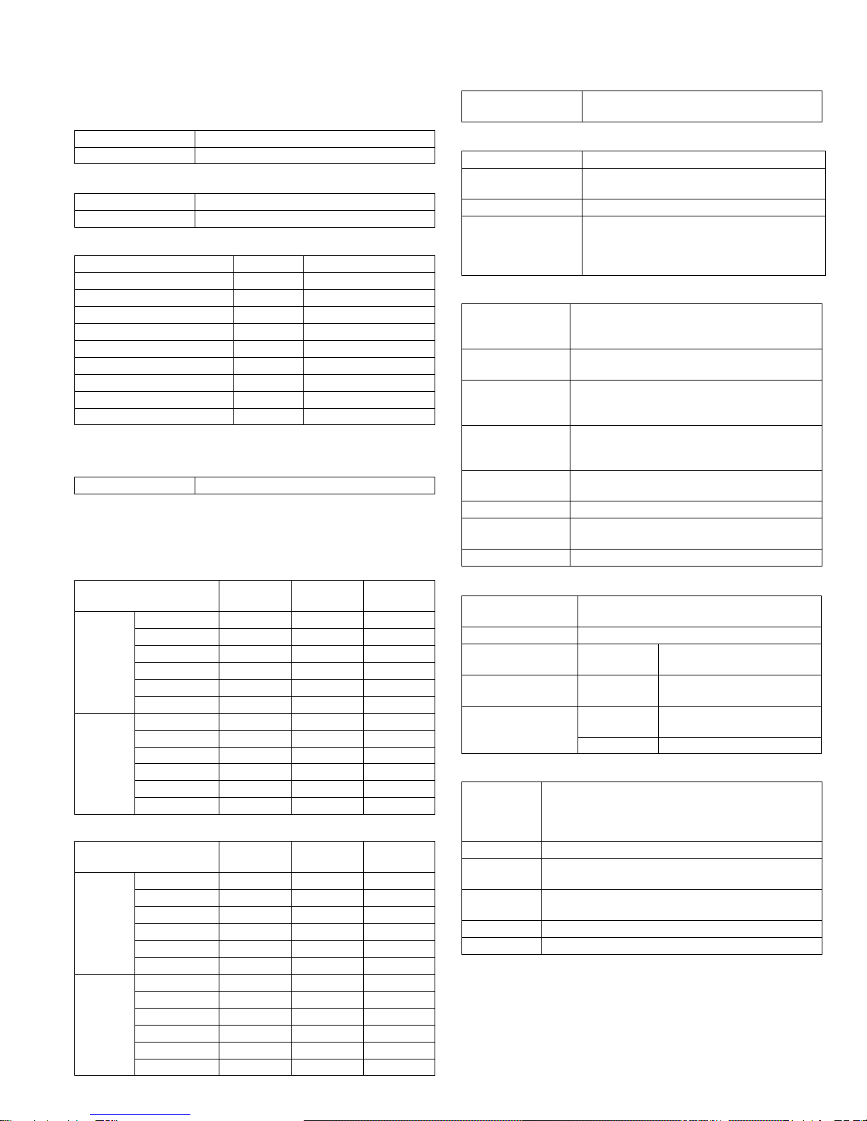
(2) Manual paper feed section
(3) Option paper feed unit
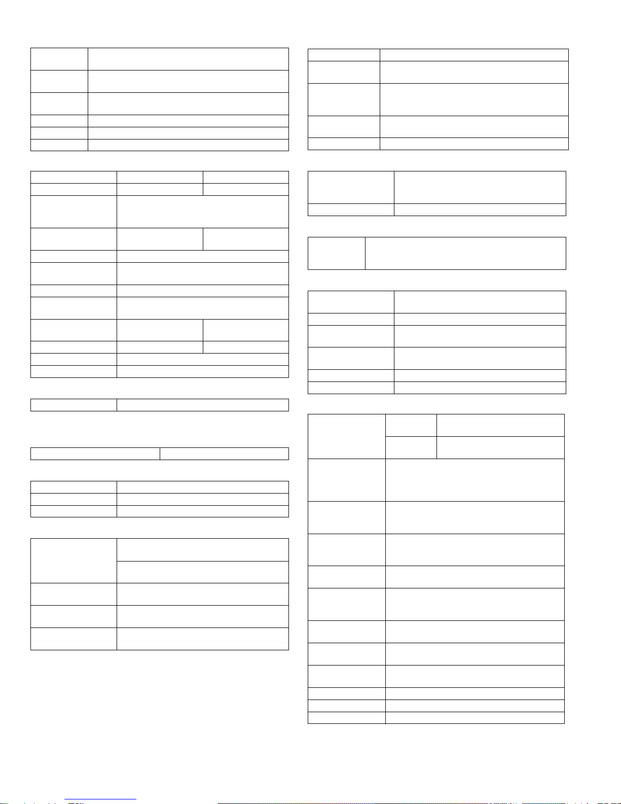
G. Job speed
Condition:With SPF/RSPF A4/Letter Normal 1cassette
H. Multi copy
I. Warm-up time
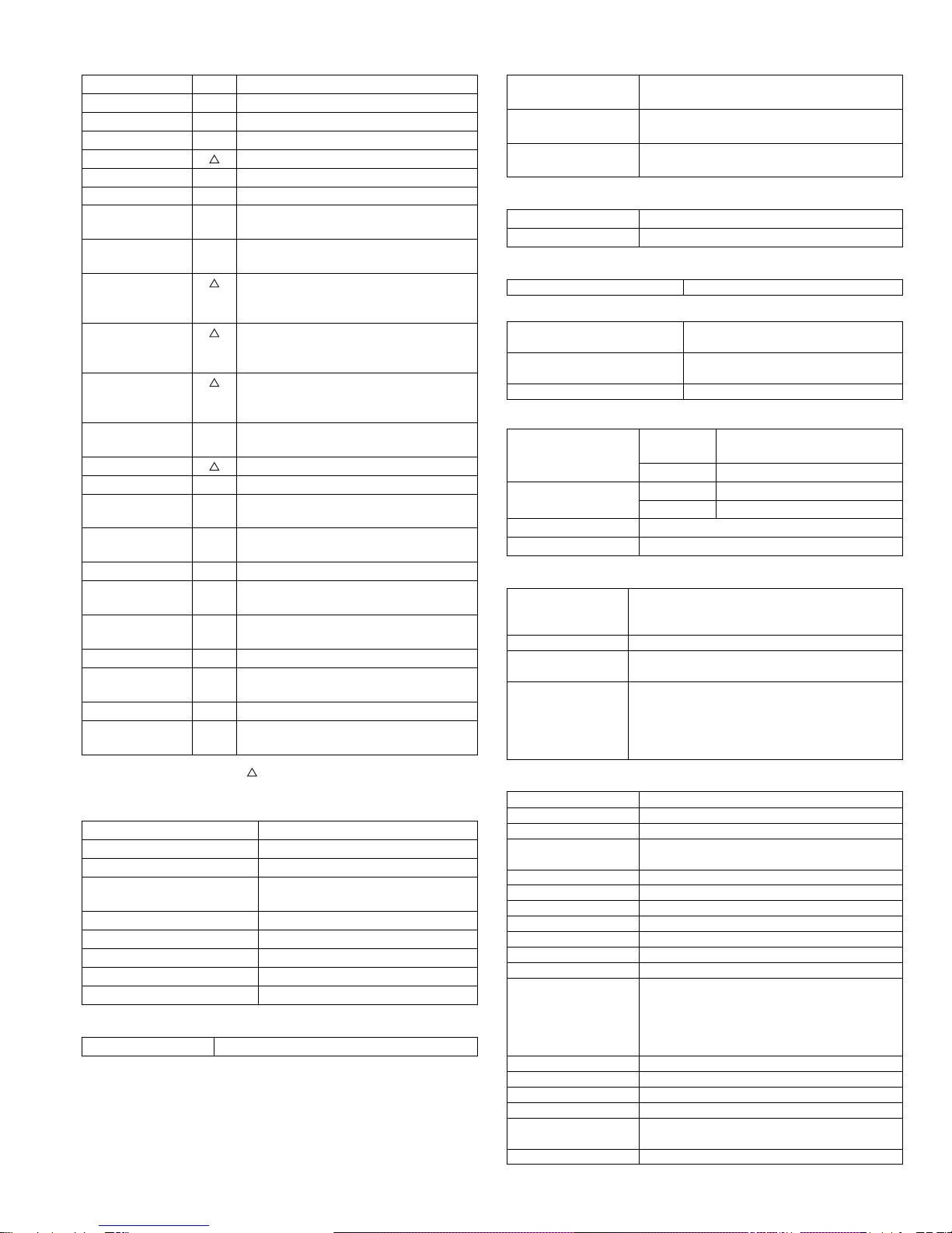
J. Copy magnification ratio
K. Print density
L. Void width
M. Auto duplex
N. Paper exit / finishing
(1) Electronic sort board (Option)
Paper feed
size A3 ~ A6, 11" x 17" ~ 8.5" x 5.5"
Paper feed
capacity 100 sheets(56 ~ 80g/m²)
Detection Size detection not available,
paper empty detection available
Weight 56 ~ 200g/m² (15 ~ 34 lbs.)
Special paper Recycled paper, OHP film, labels
Paper feed Single except for recycled paper
1-step paper feed unit 2-step paper feed unit
Model AR-D24 AR-D25
Paper feed size A3, B4, A4, A4R, B5, B5R
11" x 17", 8.5" x 14", 8.5" x 13",
8.5" x 11", 8.5" x 11"R
Capacity
(56 ~ 80gm²) About 250 sheets x
1 step About 250 sheets x
2 steps
Paper weight 56 ~ 90 g/m² (15 ~ 21 lbs.)
Moisture preserving
heater None
Paper empty detection Available
Paper size setting User setting
Paper size detection:None
External dimensions
(W x D x H) 590 x 471 x 88mm 590 x 471 x 173.5mm
Weight About 4.7kg About 10kg
Special paper Recycled paper
Power Supplied from the machine
S-S (1st step) 100% (document replacement rate)
Max. number of multi copy 999 sheets
Warm-up time 45 sec
Pre-heat Available
Jam recovery Within 45 sec
Fixed
magnification
ratio
AB system:
50, 70, 81, 86, 100, 115, 122, 141, 200%
Inch system:
50, 64, 77, 95, 100, 121, 129, 141, 200%
Zooming 25 ~ 400%
SPF/RSPF(50 ~ 200%)
Independent
zooming(vertical) Available (25 ~ 400%)
SPF/RSPF(50 ~ 200%)
Independent zooming
(horizontal) Available (25 ~ 400%)
SPF/RSPF(50 ~ 200%)
Density mode Auto / Text / Photo
No. of manual
adjustment 5 steps (Text / Photo)
Resolution Writing: 600 x 600dpi
Reading: 600 (main) x 600 (sub) (PHOTO mode)
600 (main) x 300 (sub) (AE mode)
Gradation Reading: 256 gradations
Writing: Binary
Toner save mode Set by the user program
Void area Lead edge 1 ~ 4mm,
rear edge 4mm or less,
both sides 4mm or less
Image loss 4mm or less
Standard/
Option Standard provision (AR-M205 only)
(D →D / D →S enable only when RSPF is installed)
Not available for AR-M160
Paper exit section
capacity Face down 250 sheets
Full detection None
Finishing Dual function board:
Option (AR-EB7)
Electronic sort
capacity A4 (8.5" x 11") standard document 100 sheets
Offset function Available (by the shifter)
Staple function None
Electronic sort Sorting 100 sheets of A4 standard
documents
Grouping 100 sheets of A4 standard
documents
Rotation copy If there is paper of same size as the document,
the image is rotated to copy even though the
paper is set in the different direction from the
document direction.
2 in 1, 4 in 1 Copies of 2 pages or 4 pages are integrated into
one surface. Divided by solid lines,
(Selectable by the user program.)
Edge erase Images surrounding the document are erased
when copying. (Adjustable in 5 ~ 20mm by the
user program.)
Center erase The image at the center is erased when copying.
(Adjustable in 5 ~ 20mm by the user program.)
Margin shift Binding margin is made at the left edge of the set
documents.
(Adjustable in 5 ~ 20mm by the user program.)
Memory for
electronic sort 16MB
* Memory loading
capacity A4 standard 100 pages
Memory expansion DIMM memory slot x 1, max. 256MB x 1 slot +
16MB (Max. 272MB in total)
USB2.0 Standard provision of E-sort
SPLC (JBIG-GDI) Supported when E-sort is installed.
ROPM Supported when E-sort is installed.
!"#$%

AR-M205 SPECIFICATIONS 2-3
O. Additional functions
O : Available :Installation of the option is required.
X : Not available
P. Other specifications
Q. Package form
R. External view
S. Power source
T. Power consumption
* EnergyStar conformity
U. Digital performance
V. Printing function
W. Scanner function
APS O
AMS O
Auto tray switching O
Memory copy O
Rotation copy
E-sort O Option
Rotation sort X
Independent
zooming O
1 set 2 copy O Enlargement invalid/SPF invalid (Patent
rotation)
Binding margin Default AB series:
10mm (5, 10, 15, 20mm)
Inch series: 1/2 inch (1/4, 1/2, 3/4, 1 inch)
Edge erase Default AB series:
10mm (5, 10, 15, 20mm)
Inch series: 1/2 inch (1/4, 1/2, 3/4, 1 inch)
Center erase Default AB series:
10mm (5, 10, 15, 20mm)
Inch series: 1/2 inch (1/4, 1/2, 3/4, 1 inch)
Black/white
reverse X
2in1/4in1
Sorter O Offset function (Shifter) provided
Preheating O The conditions are set by the user
program.
Auto shut-off O The conditions are set by the user
program.
User programming O
Total counter O Supports Total counter, Scan counter, and
Copy counter.
Coin vendor
support O (Supports I/F only.)
Auditor support O (Supports I/F only.)
Duplex O (Standard provision for the model of 20-
sheet model only)
Toner save O (Set according to the destination)
Department
management O (Copy: 20 Dept.)
Photoconductor type OPC (Organic Photo Conductor)
Photoconductor drum dia. 30mm
Copy lamp Cold cathode fluorescent lamp (CCFL)
Developing system Dry 2-component magnetic brush
development
Charging system Saw teeth charging
Transfer system (+) DC corotron
Separation system (-) DC corotron
Fusing system Heat roller
Cleaning system Contact blade
Body Body / Accessories
External dimensions
(W x D x H) 590 x 577 x 520 mm(AR-M205)
590 x 577 x 470 mm(AR-M160)
Occupying area
(W x D) 590 x 531mm
(When the manual tray is installed.)
Weight About 31.3kg (AR-M160)
About 35.1kg (AR-M205)
Voltage AC120V, 220V, 230V, 240V ±15%
Frequency 50/60Hz common
Max. power consumption 1200W
Average power consumption in
operation Less than 550W
Power consumption when
standby 5W(Not include option)
Energy consumption efficiency Less than 25W
Resolution Reading 600 x 600dpi (PHOTO mode)
600 x 300dpi (AE mode)
Writing 600 x 600dpi
Gradation Reading 256 gradations
Writing Binary
Memory Simplex:16MB Duplex:32MB
Hard disk None
Print speed <Standard>12ppm
(With the AR-EB7 installed)
16ppm (AR-M160) / 20ppm (AR-M205)
Data resolution 600dpi
Option memory 16MB (with the AR-EB7 installed)
256MB (AR-SM5) can be added to the AR-EB7.
Printer driver Two drivers for the case when the AR-EB7 is
installed and when it is not are automatically
installed by plug & play.
<Standard> SHARP GDI driver
<with the AR-EB7 installed> SPLC driver
Type Flat bed color scanner
Scan system Document table/document feed unit
Light source White CCFL
Resolution Basic 600 x 1200dpi
Set range: 50 ~ 9600dpi
Document Sheet/Book
Effective scan range OC/SPF: about 297(length) x 431(width) mm
Scan speed OC/SPF: 2.88msec/line (Color)
Input data 1bit or 12bit
Output data 1bit or 8bit
Scan color Black and white binaryGray scaleFull color
Protocol TWAIN/WIA (XP only) / STI
Interface USB1.1
USB2.0
(Option support: High-speed mode/Full speed
mode (Switched by the user program.))
(Supported when E-sort is installed)
Scanner utility Sharp Desk/Button Manager
Drop-out color Provided
Scanner button Provided (6)
Supported OS Windows98/ME/2000/XP
Void area Lead edge/rear edge (2.5mm) on the driver
side Left/right: 3.0mm
WHQL support Yes
& !"#$%

AR-M205 CONSUMABLE PARTS 3-1
[3] CONSUMABLE PARTS
1.Supply system table
A.USA/CANADA/Latin America
B. Middle East/Africa/Taiwan/Philippine
C. Europe/East Europe
D. Asia
E.Hong Kong/China
NO Name Content Life Product name Remark
1 Toner cartridge(Black)
<With IC> Toner
(Toner: Net Weight 537g)
Vinyl bag
x10
x10
160K AR-202MT Life setting by A4 6% document
2 Developer Developer
(Developer : Net Weight 400g) x10 500K AR-202MD
3 Drum kit Drum
Drum fixing plate x1
x1 50K AR-202DR
NO Name Content Life Product name Remark
1 Toner cartridge(Black)
<With IC> Toner
(Toner: Net Weight 537g)
Vinyl bag
x10
x10
160K AR-202ET Life setting by A4 6% document
2 Developer Developer
(Developer : Net Weight 400g) x10 500K AR-202CD
3 Drum kit Drum
Drum fixing plate x1
x1 50K AR-202DR
NO Name Content Life Product name Remark
1 Toner cartridge(Black)
<With IC> Toner
(Toner: Net Weight 537g)
Vinyl bag
x10
x10
160K AR-202LT Life setting by A4 6% document
2 Developer Developer
(Developer : Net Weight 400g) x10 500K AR-202LD
3 Drum kit Drum
Drum fixing plate x1
x1 50K AR-202DM
NO Name Content Life Product name Remark
1 Toner cartridge(Black)
<With IC> Toner
(Toner: Net Weight 537g)
Vinyl bag
x10
x10
160K AR-202CT Life setting by A4 6% document
2 Developer Developer
(Developer : Net Weight 400g) x10 500K AR-202CD
3 Drum kit Drum
Drum fixing plate x1
x1 50K AR-202DR
NO Name Content Life Product name Remark
1 Toner cartridge(Black)
<With IC>
(Hong Kong only)
Toner
(Toner: Net Weight 645g)
Vinyl bag
x10
x10
160K AR-202CT-C Life setting by A4 6% document
2 Toner cartridge(Black)
<With IC>
(China only)
Toner
(Toner: Net Weight 645g)
Vinyl bag
x1
x1
19K AR-203ST-C Life setting by A4 6% document
3 Developer Developer
(Developer : Net Weight 4500) x10 500K AR-202CD-C
4 Drum kit Drum
Drum fixing plate x1
x1 50K AR-202DR-C
!"# !$%&'(

AR-M205 CONSUMABLE PARTS 3-2
2. Environmental conditions
A. Transport conditions
(1) Transport conditions
(2) Storage conditions
B. Use conditions
C. Life(packed conditions)
Photoconductor drum (36 months from the production month)
Developer, toner (24 months from the production month)
3. Production number identification
<Toner cartridge>
The label on the toner cartridge shows the date of production.
<Drum cartridge>
The lot number, printed on the front side flange, is composed of 6 digits,
each digit showing the following content:
Temperature
Humidity (%)
Temperature
Humidity (%)
Humidity (%)
Temperature
Use envi-
ronment
conditions
123456
1 Alphabet
Indicates the model conformity code. A for this model.
2 Number
Indicates the end digit of the production year.
3 Number or X, Y, Z
Indicates the month of packing.
X stands for October, Y November, and Z December.
4/5 Number
Indicates the day of the month of packing.
6 Alphabet
Indicates the production factory. "A" for Nara Plant, “C“ for
SOCC
Ver.No.Production
place
Serial
number
Year/
Month/
Day
) !"# !$%&'(

AR-M205 EXTERNAL VIEWS AND INTERNAL STRUCTURES 4-1
[4] EXTERNAL VIEWS AND INTERNAL STRUCTURES
1. Appearance
2. Internal
1 Document feeder cover (when the SPF/
RSPF is installed) /document cover
(when the document cover is installed)
2 Document glass 3 Handles
4 Power switch 5 Operation panel 6 Paper output tray
7 Front cover 8 Paper trays 9 Side cover
10 Side cover handle 11 Bypass tray guides 12 Bypass tray
13 Bypass tray extension 14 Charger cleaner 15 USB 1.1 port
16 Parallel port 17 USB 2.0 port (when the dual function
board is installed)
18 Document feeder tray
(when the SPF/RSPF is installed) 19 Original guides
(when the SPF/RSPF is installed) 20 Feeding roller cover
(when the SPF/RSPF is installed)
21 Right side cover
(when the SPF/RSPF is installed) 22 Exit area
(when the SPF/RSPF is installed) 23 Reversing tray
(when the RSPF is installed)
24 Toner cartridge lock release lever 25 Toner cartridge 26 Roller rotating knob
27 Fusing unit release levers 28 Photoconductive drum 29 Fusing unit paper guide
17 1
1
3
9
10
131211
6 5
2
3
7
4
16
14
15
8
18 19 20
21 22 23
2928
27
26
25
24
!"#$%

AR-M205 EXTERNAL VIEWS AND INTERNAL STRUCTURES 4-2
3. Operation Section
1 SCAN MENU key 2 SCAN key/indicator 3 ON LINE key/indicator
4 ORIGINAL TO COPY key/indicators
(AR-M205 only) 5 DUAL PAGE COPY key/indicator 6 XY-ZOOM key/indicator
7 SORT/GROUP key/indicators
(when the dual function board is
installed)
8 ORIGINAL DATA indicator
(when the dual function board is
installed)
9 2 IN 1 / 4 IN 1 key/indicators
(when the dual function board is
installed)
10 ERASE key/indicators
(when the dual function board is
installed)
11 MARGIN SHIFT key/indicator
(when the dual function board is
installed)
12 AUTO/TEXT/PHOTO key / indicators
13 AUDIT CLEAR key 14 AUTO PAPER SELECT indicator 15 Alarm indicators
16 POWER SAVE indicator 17 Display 18 Copy ratio display key ( )
19 ZOOM indicator 20 Zoom keys ( , ) 21 INTERRUPT key ( ) / indicator
22 Light and Dark keys ( , ) / indicators 23 ORIGINAL SIZE ENTER key /
ORIGINAL SIZE indicators 24 PAPER SIZE indicators
25 PAPER SIZE ENTER key 26 SPR/RSPF indicator
(when the SPF/RSPF is installed) 27 TRAY SELECT key ( )
28 AUTO IMAGE key/indicator 29 Paper feed location/misfeed location
indicators 30 PRESET RATIO selector keys ( , ) /
indicators
31 [ ] key 32 Numeric keys 33 READ-END key ( )
34 START key ( ) /indicators 35 CLEAR ALL key ( ) 36 CLEAR key ( )
1
2
SCAN ON LINE
ORIGINAL TO COPY
XY-
ZOOM
DUAL
PA G E
COPY
12 34 56
ON LINE
XY-
ZOOM
DUAL
PA G E
COPY
PRESET
A
UTO
TR
A
Y
ZE
L
PAPER
SIZE
X
17
2
0
1
0
5
1
4
9
7
6
1
2
1
2
X
14
X
11
X
11
X
5½
T
RA
The AR-M160 is shown below.
1 2 3 4 5 6
ORIGINAL DATA
SORT
AUDIT CLEAR
AUTO PAPER SELECT
POWER SAVE
INTERRUPT
CLEAR
CLEAR ALL
START
ZOOM
READ-END
PRESET RATIO
AUTO
IMAGE
TRAY
SELECT
ORIGINAL SIZE
ENTER
AUTO
ORIGINAL
SIZE
PAPER
SIZE
TEXT
PHOTO
135
11
X
17
200
%
100
%
50
%
141
95
77
64
129
121
8½
X
14
8½
X
11
8½
X
11
8½
X
5½
EXTRA
25 400%
2 IN 1
4 IN 1
GROUP
EDGE
ERASE
MARGIN
SHIFT
CENTER
789
10 11 12 13 14 15 16 17 18 19 20 21
22 23 24 25 26 27 28 29 30 31 32 33 34 35 36
& !"#$%

AR-M205 EXTERNAL VIEWS AND INTERNAL STRUCTURES 4-3
4. Motor, solenoid, clutch
No. Name Code Function operation
1 Mirror motor MRM Drives the optical mirror base (scanner unit).
2 Shifter motor SHTM Shifts the paper exit tray.
3 Toner motor TM Toner supply
4 Duplex motor DPX Switchback operation and paper exit motor in duplex.
5 Cooling fan motor CFM Cools the inside of the machine.
6 Main motor MM Drives the machine.
7 1st tray paper feed clutch CPFC1 Drive the pick up roller
8 PS clutch RRC Drives the resist roller
9 Paper feed solenoid CPSOL1 Solenoid for paper feed from cassette
10 Resist roller solenoid RRS Resist roller rotation control solenoid
11 Manual paper transport clutch MPTC Drives the manual paper transport roller.
12 Manual paper feed clutch MPFC Drives the manual paper feed roller.
13 Manual paper feed solenoid MPFS Manual paper feed solenoid
14 2nd tray transport clutch CPFC2 Drives the 2nd tray transport roller.
15 2nd tray transport solenoid FSOL1 2nd tray transport solenoid
16 2nd tray paper feed clutch CPFC1 Drives the 2nd tray paper feed roller.
17 2nd tray paper feed solenoid PSOL2 2nd tray transport solenoid
18 Exhaust fan motor VFM Cools the inside of the machine.
1
4
6
7
8
9
10
11
12
13
18
14
15
16
17
5
3
2
' !"#$%

AR-M205 EXTERNAL VIEWS AND INTERNAL STRUCTURES 4-4
5. Sensor, switch
No. Name Code Function operation
1 Mirror home position sensor MHPS Detects the mirror (scanner unit) home position.
2 Side door switch DSWR Side door open detection
3 Paper exit sensor (paper exit side) POD1 Detects paper exit.
4 Shifter home position sensor SFTHP Shifter home position detection
5 Paper exit sensor (DUP side) PDPX Paper transport detection
6 Thermistor RTH Fusing section temperature detection
7 Thermostat Fusing section abnormally high temperature detection
8 Toner density sensor TCS Toner quantity detection
9 2nd tray detection switch 2nd tray detection
10 Manual sensor MPED Manual transport detection
11 2nd tray door open/close sensor DRS2 2nd tray door open/close detection
12 2nd tray door paper pass sensor PPD2 2nd tray paper entry detection
13 2nd tray paper empty sensor CSS2 2nd tray paper empty detection
14 Paper in sensor PIN Paper transport detection
15 Cassette empty Tray paper entry detection
16 Front cover SW Front cover open detection
17 Power switch MAIN SW Turns ON/OFF the main power source.
1
16
17
4
5
6
7
8
9
10
11
12
14
15
13
2
3
!"#$%

AR-M205 EXTERNAL VIEWS AND INTERNAL STRUCTURES 4-5
6. PWB unit
No. Name Function operation
1 Copy lamp Inverter PWB Copy lamp control
2 I / F PWB USB1.1, IEEE1284 I/F
3 CCD sensor PWB Image scanning
4 Main control PWB Main control PWB
5 Tray PWB Shifter motor control
6 IMC2 PWB Electronic sort, USB2.0 << Option:AR-EB7>>
7 2nd cassette PWB 2nd cassette control
8 High voltage PWB High voltage control
9 Power PWB AC power input/DC power control
10 Operation main PWB Operation panel input/Display, operation panel section control
1
10
9
8
2
4
5
7
3
6
( !"#$%

AR-M205 EXTERNAL VIEWS AND INTERNAL STRUCTURES 4-6
7. Cross sectional view
No. Name Function/Operation
1 Copy lamp Image radiation lamp
2 Copy lamp unit Operates in synchronization with No. 2/3 mirror unit to radiate documents
sequentially.
3 LSU unit Converts image signals into laser beams to write on the drum.
4 Lens unit Reads images with the lens and the CCD.
5 MC holder unit Supplies negative charges evenly on the drum.
6 Paper exit roller Used to discharge paper.
7 Transport roller Used to transport paper.
8 Upper heat roller Fuses toner on paper (with the teflon roller).
9 Lower heat roller Fuses toner on paper (with the silicon rubber roller).
10 Waste toner transport roller Transports waste toner to the waste toner box.
11 Drum unit Forms images.
12 Transfer charger unit Transfer images (on the drum) onto paper.
13 DUP follower roller
14 Duplex transport roller Transports paper for duplex .
15 Resist roller Takes synchronization between the paper lead edge and the image lead edge.
16 Manual paper feed tray Manual paper feed tray
17 Manual paper pick up roller Picks up paper in manual paper feed.
18 No. 2/3 mirror unit Reflects the images from the copy lamp unit to the lens unit.
19 Manual transport roller Transports paper from the manual paper feed port.
20 2nd tray paper transport roller Transports paper from the 2nd tray.
21 2nd tray paper pick up roller
(semi-circular roller) Picks up paper from the 2nd tray.
22 1st tray paper feed roller
(semi-circular roller) Picks up paper from the 1st tray.
23 MG roller Puts toner on the OPC drum.
1 4
6
7
8
9
10
11
12
13
14
15
16171920212223
53
18
2
) !"#$%

AR-M205 UNPACKING AND INSTALLATION 5-1
[5]UNPACKING AND INSTALLATION
1.Installing conditions
A.Copier installation
Do not install your copier in areas that are:
•damp, humid, or very dusty
•exposed to direct sunlight
•poorly ventilated
•subject to extreme temperature or humidity changes, e.g., near an air
conditioner or heater.
•Be sure to allow the required space around the machine for servicing
and proper ventilation.
B.Power source
•Use an exclusive-use power outlet. If the power plug of this machine is
inserted into a power outlet commonly used with other illumination
units, flickers of the lamp may be result. Use a power outlet which is not
used commonly with any illumination units.
•Avoid complex wiring.
C.Grounding wire connection.
•To avoid danger, be sure to connect a grounding wire. If no grounding
wire is connected and a leakage occurs, a fire or an electric shock may
be result.
2.Removal of protective material and fixing
screw
1) Remove all tapes and protective material.
•Remove all tapes, then open the document cover and remove the
protective material of sheet shape
2) Remove the fixing screw.
•Use a coin to remove the fixing screw.
•The fixing screw is required when transporting the machine. Keep it in
the tray. (Refer to the later description.)
3.Installing procedure
A.Developer cartridge installation
1) Open the manual tray, and open the side cover.
2) Open the front cover.
•Hold the both sides and pull down to open.
3) Loosen the screw and remove the developer cartridge.
4) Remove the developer tank from the developer cartridge.
5) Supply developer into the developer tank while rotating the MG roller
in the arrow direction.
* Shake the developer bag enough before opening it.
Note:Check that the DV seal is free from developing agent. If developing
agent is attached to the DV seal, clean it carefully.
Check to insure that the hook is engaged in two positions.
6) Attach the developer tank to the developer cartridge.
* After supplying developer into the developer cartridge, do not tilt or
shake the developer cartridge.
7) Attach the developer cartridge to the copier, and fix it with the screw.
MG roller
Hook
!"

AR-M205 UNPACKING AND INSTALLATION 5-2
B.Toner cartridge installation
1) Shake the toner cartridge several times horizontally, and remove the
tape.
* Do not hold the shutter lever when shaking.
* After removing the tape, do not tilt or shake the toner cartridge.
2) Attach the toner cartridge to the copier.
3) Pull the shutter lever.
Close the front cover A, then close the side cover B.
•When closing the front cover, gently press the both sides.
•When closing the side cover, hold the knob.
•When closing the covers, be sure to close the front cover first, then
close the side cover. If closed in a wrong sequence, the covers may be
broken.
4.Removal and storage of fixing screw
1) Lift the knob and gently pull out the tray.
2) Hold the paper pressure plate and turn the fixing screw in the arrow
direction.
3) Store the fixing pin and the fixing screw in the tray.
•Store the fixing screw which was removed in the above procedure 2 and
the fixing screw which was removed in procedure 2 of 2.
•Removal of protective material and fixing screw in the storage place in
the tray.
Shutter
Tape
Handle
4 or 5 times
Screw
Pressure
plate
lock
# !"

AR-M205 UNPACKING AND INSTALLATION 5-3
5. Changing the copy paper size in the tray
Note
•The paper size setting cannot be changed when the machine has
stopped temporarily due to running out of paper or a misfeed, or during
interrupt copying.
•During printing (even in copy mode), the paper size setting cannot be
changed.
•5-1/2" x 8-1/2" size paper can only be selected in upper paper tray.
•Do not load paper that is a different size than the paper size setting.
Copying will not be possible.
1) Hold down the [PAPER SIZE ENTER] key for more than 5 seconds to
set the selected paper size.
The currently selected paper feed location indicator will blink and the
corresponding paper size (which is currently set) indicator will light
steadily.
All other indicators will go out.
2) Use the [TRAY SELECT] key to select the paper tray for which you
wish to change the paper size setting.
Each time the [TRAY SELECT] key is pressed, a paper tray will be
indicated with a blinking paper feed location indicator.
3) Use the [ORIGINAL SIZE ENTER] key to select the paper size.
The indicator of the selected paper size lights up.
4) Squeeze the lock lever of the front guide and slide the front guide to
match the width of the paper, and move the left guide to the
appropriate slot as marked on the tray.
•The front guide is a slide-type guide. Grasp the locking knob on the
guide and slide the guide to the indicator line of the paper to be loaded.
•The left guide is an insert-type guide. Remove it and then insert it at the
indicator line of the paper to be loaded.
•When using 11" x 17" sized paper store the left guide in the slot at the
left front of the paper tray.
6) Press the [START] key and then the [PAPER SIZE ENTER] key.
To change the paper size setting of another tray, repeat steps 2 to 3
after pressing the [START] key.
Note
Affix the paper size label for the paper size selected in step 3 to the label
position on the right end of the tray.
GINAL
PAPER
SIZE
11
X
17
8½
X
14
8½
X
11
8½
X
11
8½
X
5½
EXTRA
TRAY
SELECT
ORIGINAL SIZE
ENTER
GINAL
PAPER
SIZE
11
X
17
8½
X
14
8½
X
11
8½
X
11
8½
X
5½
EXTRA
Left guide
Front guide
START
$ !"

AR-M205 ADJUSTMENT 6-1
[6]ADJUSTMENTS
1.Adjustment item list
2.Copier adjustment
A.Process section
(1) Developing doctor gap adjustment
1) Loosen the developing doctor fixing screw A.
2) Insert a thickness gauge of 1.5mm to the three positions at 20mm
and 130mm from the both ends of the developing doctor as shown.
3) Push the developing doctor in the arrow direction, and tighten the
developing doctor fixing screw. (Perform the same procedure for the
front and the rear frames.)
4) Check the clearance of the developing doctor. If it is within the
specified range, then fix the doctor fixing screw with screw lock.
* When inserting a thickness gauge, be careful not to scratch the
developing doctor and the MG roller.
<Adjustment specification>
(2) MG roller main pole position adjustment
1) Remove and separate the waste toner box and put the developing
unit on a flat surface.
2) Tie a string to a needle or a pin.
3) Hold the string and bring the needle close to the MG roller
horizontally. (Do not use paper clip, which is too heavy to make a
correct adjustment.) (Put the developing unit horizontally for this
adjustment.)
4) Do not bring the needle into contact with the MG roller, but bring it to
a position 2 or 3mm apart from the MG roller. Mark the point on the
MG roller which is on the extension line from the needle tip.
5) Measure the distance from the marking position to the top of the
doctor plate of the developing unit to insure that it is 18mm.
If the distance is not within the specified range, loosen the fixing
screw A of the main pole adjustment plate, and move the adjustment
plate in the arrow direction to adjust.
Section Adjustment item Adjustment procedure/SIM No.
A Process
section (1) Developing doctor gap adjustment Developing doctor gap adjustment
(2) MG roller main pole position adjustment MG roller main pole position adjustment
(3) Developing bias voltage check
(4) Main charger voltage check
B Mechanism
section (1) Image position adjustment SIM-50
(2) Main scanning direction (FR direction) distortion balance
adjustment No. 2/3 mirror base unit installing position adjustment
Copy lamp unit installing position adjustment
(3) Main scanning direction (FR direction) distortion adjustment Rail height adjustment
(4) Sub scanning direction (scanning direction) distortion
adjustment Winding pulley position adjustment
(5) Main scanning direction (FR direction) magnification ratio
adjustment SIM 48-1
(6) Sub scanning direction (scanning direction) magnification ratio
adjustment OC mode in copying (SIM 48-1)
SPF mode in copying (SIM 48-5)
(7) Off center adjustment OC mode (SIM 50-12)
SPF mode (SIM 50-12)
(8) SPF white correction pixel position adjustment
(
required in an SPF model when replacing the lens unit)
SIM63-7
C Image density
adjustment (1) Copy mode SIM 46-1
Developing doctor gap
Both ends (20mm from the both ends) :
C (Center) (150mm from the both ends) :
1.5 mm
+0.1
- 0.15
1.55 mm
+0.15
- 0.2
!"##$#%&

AR-M205 ADJUSTMENT 6-2
(3)Developing bias voltage check
Note:Use a digital multi-meter with an internal resistance of 10MΩor
more.
1) Set the digital multi-meter range to DC700V.
2) Put the test rod of the digital multi-meter on the developing bias
voltage output check pin.
3) Turn on the power, execute SIM25-1.
<Specification>
(4) Grid bias voltage check
Note:Use a digital multi-meter with an internal resistance of 10MΩor
more.
1) Set the digital multi-meter range to DC700V.
2) Put the test rod of the digital multi-meter on the grid bias voltage
output check pin.
3) Turn on the power.
(The voltage is outputted in the grid bias High output mode during
warming up, and in the grid bias Low output mode when warming up
is completed.)
<Specification>
B.Mechanism section
Note: If a jam error or paper empty occurs during copying in the
adjustment by the simulation, the image data are not saved, and
therefore recopying is required.
(1)Image position adjustment
a.OC image lead edge position adjustment (SIM 50-1)
Note:In advance to this adjustment, the sub scanning magnification ratio
adjustment must be performed.
1) Set a scale on the OC table as shown below.
2) Make a copy.
3) Check the copy output. If necessary, perform the following
adjustment procedures.
4) Execute SIM 50-1.
5) Set the OC lead edge position set value (Exposure display
<<PHOTO>> ON) to [1]
The OC image scanning start position is shifted inside the document
edge.
6) Set the main cassette lead edge void adjustment value (Exposure
display <<TEXT>> ON) * to [1]
The lead edge void becomes the minimum.
7) Set the main cassette print start position value (Exposure display
<<AUTO+MAIN CASSETTE LAMP>> ON) to [1] and make a copy.
The print start position is shifted inside the document edge.
8) Measure the image loss R of the copied image. Enter the set value of
the image scanning lead edge position (Exposure display
<<PHOTO>> ON) again.
•1 step of the set value corresponds to about 0.1mm shift.
•Calculate the set value from the formula below.
R/0.1(mm) = Image loss set value
<R: Image loss measurement value (mm)>
Example: 4/0.1 = 40 = about 40
Note:If the set value is not obtained from the above formula, perform the
fine adjustment.
Mode Specification
Developing bias voltage DC - 400±8V
Mode Specification
Grid bias LOW DC - 400±8V
Grid bias HIGH DC - 525±10V
5
10
5mm
4mm
*The dimension varies depending on the model.
10
5mm
0mm
5
*The scanning edge is set.
(A line may be printed by scanning the document edge.)
' !"##$#%&
Other manuals for AR-M160
4
This manual suits for next models
1
Table of contents
Other Sharp Copier manuals

Sharp
Sharp AL-1600 User manual

Sharp
Sharp AR-C150 User manual

Sharp
Sharp MX-M283 User manual

Sharp
Sharp AR-281 User manual

Sharp
Sharp SF-2218 User manual

Sharp
Sharp AR-BC260 User manual

Sharp
Sharp AR-C250 User manual

Sharp
Sharp Multi Access User manual

Sharp
Sharp AR-FN1N User manual

Sharp
Sharp AR-120E User manual

Sharp
Sharp AR-121E User manual

Sharp
Sharp AL1215 - B/W Laser - Copier User manual

Sharp
Sharp AR-LC1 User manual

Sharp
Sharp AR-405 User manual

Sharp
Sharp AR-287 User manual

Sharp
Sharp SF-825 User manual

Sharp
Sharp SF-2030 User manual

Sharp
Sharp AR-M201 Setup guide

Sharp
Sharp IMAGER AR-5316 User manual

Sharp
Sharp AR-C250 User manual