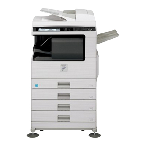
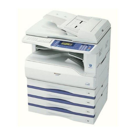
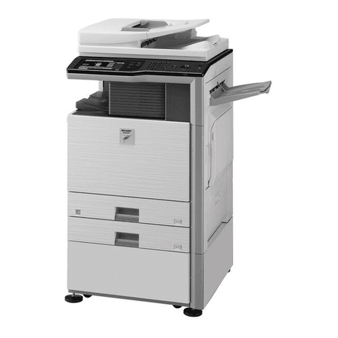
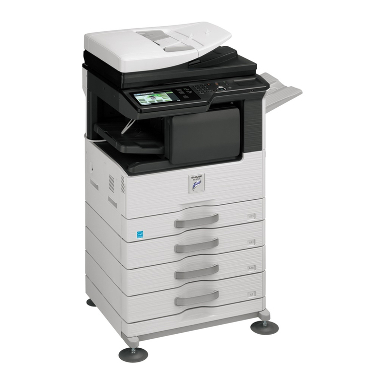
Sharp SF-2220 User manual

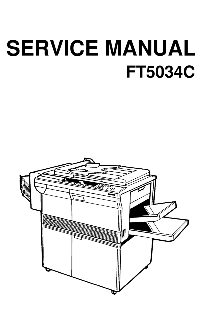
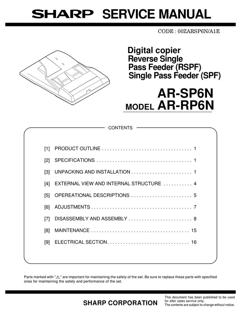
SERVICE MANUAL
CODE: 00ZSF2320/A1E
MODEL SF-2220
MODEL SF-2320
Option •Paper tray (SF-UB15)
•Two-step paper feed unit (SF-CM15)
•One-step paper feed unit (SF-CM16)
•10-bin staple sorter (SF-S54) @
•Auto document feeder (SF-A18) @
•Reverse automatic document feeder
(SF-A57) @
•Multi paper feed unit (SF-MF15)
@For the options, refer to their service manuals.
•This model is a minor change model based on the SF-2020/2120. This Service
Manual described only the changed items from the base model. For the items
common with the SF-2020.2120, refer to the Service Manual of the SF-2020/2120.
•The SF-2220 /2320 circuit diagrams are same as those of the SF-2020/2120.
Therefore, please refer to the SF2020/2120 circuit diagrams.
CONTENTS
SHARP CORPORATION This document has been published to be used
for after sales service only.
The contents are subject to change without notice.
SF-2220
Parts marked with "!" is important for maintaining the safety of the set. Be sure to replace these parts with specified
ones for maintaining the safety and performance of the set.

[1] PRODUCT OUTLINE
1. Different points between SF-2220/2320 and SF-2020/2120
Model name SF-2020 SF-2120 SF-2220 SF-2320 Remark
Item
Multi paper feed unit Standard
provision Option
(SF-MF15)
Personal counter
(SF-71A/B) Options
(Service item) Service item
To install the Personal Counter, a Counter
fixing plate (LPLTM4963FCZZ), four Screw
(XHPSD40P06000 ×2, XBSSD30P06000 ×2)
and a Edge plate (LBSHL0323FCZZ) are
required.
Paper size detection Available Black The paper size of each tray is set with the
user program. (Refer to the paper size setting
mode.)
Original cover Standard
provision Option
(SF-CV13)
Maintenance parts life Unit: 50K Unit: 60K
2. System configuration (options)
10-bin sorter SF-S17N
Automatic document feeder SF-A18
Two-step paper feed unit SF-CM15
Tray (reserve) SF-UB15
One-step paper feed unit SF-CM16
10-bin staple sorter SF-S54
Reversing automatic document feeder SF-A57
(SF-2320 only)
Multi paper feed unit SF-MF15
Original cover SF-CV13 (SF-2320 only)
1 – 1

[2] PRODUCT SPECIFICATIONS
1. Basic specifications
(1) Type: Table top
(2) Copy speed:
<SF-2220/2320>
Normal Enlargement
(Magnification) Reduction
(Magnification)
A3 11 sheets/min 10 sheets/min
(200%) 10 sheets/min
(50%)
B4 13 sheets/min 12 sheets/min 12 sheets/min
A4 (Portrait) 20 sheets/min 15 sheets/min 15 sheets/min
A4 (Landscape) 15 sheets/min 14 sheets/min 14 sheets/min
B5 (Portrait) 20 sheets/min 15 sheets/min 15 sheets/min
B5 (Landscape) 15 sheets/min 14 sheets/min 14 sheets/min
W letter 11 sheets/min 10 sheets/min 10 sheets/min
Legal 13 sheets/min 12 sheets/min 12 sheets/min
Letter (Portrait) 20 sheets/min 15 sheets/min 15 sheets/min
Letter (Landscape) 15 sheets/min 14 sheets/min 14 sheets/min
(Note) The copy speeds for enlargement and reduction are the lowest
ones.
(3) Warm up time: 45 sec or less
(4) First copy time: SF-2220
5.3 sec (Paper feed port: Upper tray)
SF-2320
5.8 sec (Paper feed port – from copier paper tray)
First copy time from each paper feed port (A4 landscape)
Paper feed port SF-2220 Paper feed port SF-2320
Body tray upper stage 5.3 sec ADU 5.8 sec
from copier
paper tray
Body tray lower stage 5.8 sec Body 1st step
Option paper feed
unit first step 6.1 sec Option paper
feed unit 1st step 6.5 sec
Option paper feed
unit second step 6.4 sec Option paper
feed unit 2nd step 6.8 sec
(5) Jam recovery time: 8 sec (Conditions: After leaving the door
open for 60 sec, the standard conditions)
(6) Multi copy Max. 99 sheets
(7) Original
SF-2220 SF-2320
Max. original size A3
Reference original size Left side/Center
Original sensing YES (Japan only)
Sensing size A3 ∼B5R
(8) Copy magnification ratio
Fixed magnification: 200, 141, 122, 115, 100, 86, 81, 70, 50% (9
steps)
Zoom range: 50% ∼200% (151 steps by the increment of 1%)
(9) Exposure
Exposure mode: Auto/Manual/Photo
No. of manual steps: 9 steps
(10) Void width
Void area: Lead edge/rear edge: 3mm or less
Image loss Normal: 4mm or less
(11) Paper exit/finishing
Paper exit tray capacity: 250 sheets
Finishing: option 10-bin sorter, 10-bin staple sorter
(12) Additional functions
Function Remark
Auto Paper Selection F
Auto Magnification ratio
Selection F
Shift F
1-set 2-copy FEnlargement is impossible.
Edge erase F
Built-in auditor
password mode F20 departments
Interruption F
Monochrom ×
AICS F
Pre-heat mode F
Auto shut off F
Auto power save F
Auto tray switching F
Cover insertion ×
OHP insertion paper ×
Overlay ×
(13) External dimensions
SF-2220 SF-2320
W x D x H mm 600 ×585 ×450 600 ×585 ×500
Occupying area
(W x D) 885 ×595 935 ×595
Weight 48.5Kg 61.2Kg
(14) Power source
Voltage: 220 ∼ 230V
Frequency: 50/60Hz common
(15) Power consumption
Max. power
consumption 1.5kw (Note) Max. when the
option is installed
Auto power shut
off 5.0W or below
2 – 1
2. Description of each section
(1) Paper feed section
SF-2220 SF-2320
Copying size A3 ∼A6
Paper feed
system 2 trays + single
manual feed 1 tray + single
manual feed
Paper feed
capacity 250 sheets ×2250sheets×1
Cassette Paper size Paper weight Paper kind Remark
Body tray
upper stage AB series:
A3 ∼A5 56 ∼80g/m2
Standard
paper,
recycled
paper SF-2120:
copier
paper
feed tray
Body tray lower
stage AB series:
A3 ∼A5 56 ∼80g/m2Standard
paper,
recycled
paper
Paper feed unit
(option) AB series:
A3 ∼A5 56 ∼80g/m2Standard
paper,
recycled
paper
SF-CM15
(2-step)
SF-CM16
(1-step)
Multi
manual
paper
feed
Multi
(option) AB series:
A3 ∼A6R 56 ∼80g/m2
Standard
paper,
specified
paper,
special
paper, OHP
film,
Second
original
paper,
postcards
(without
folding)
SF-MF15
Single AB series:
A3 ∼A6R 52 ∼
128g/m2
(2) Optical section
Light source Halogen lamp
Exposure system Slit exposure by moving the light source
Zooming system By changing the lens positions and the scan
speed.
Lens Fixed focus lens
(3) Process
Charging system (–) DC saw teeth electrode system
Transfer system (–) tungsten system
Separation system (AC) separation tungsten system
(4) Developing section
Developing system Dry, two-component magnetic brush
development (developer replacement)
Developing bias voltage DC–200V ±5V
(5) Fusing section
Fusing system Heat roller system
Upper heat roller surface temperature 190 degrees C
Heater lamp Halogen lamp 1000W ×1
(6) ADU section
Paper kind Normal paper, 56g/m2∼80g/m2
Capacity 50 sheets
Paper size B4, A4, B5
Copy void width Lead edge, 3mm or less
Rear edge, 3mm or less
3. Supply parts
Europe/U.K.
Name Content Life Product name
1 Photoconductor kit Photoconductor drum x 1
Cleaner blade x 1
Drum separation pawl x 2
60K SF-226DM
2 Black developer Black developer (530g) x 10 60K x 10 SF-226LD
3 Black toner Black toner cartridge (240g) x 10 6K x 10 SF-226LT
4 Upper heat roller kit Upper heat roller x 1
Upper separation pawl x 4
Fusing bearing x 1
120K SF-216HU
5 Lower heat roller kit Lower heat roller x 1
Lower separation pawl x 4 120K SF-220LH
6 Staple cartridge Staple cartridge (For SF-S54) x 3 5K staples x 3 SF-LS12
7 Upper heat roller Upper heat roller x 1 120K SF-216HU
8 Upper separation pawl Upper separation pawl x 4 x 10 120K x 10 SF-216UP
9 Heat roller gear Heat roller gear x 10 120K x 10 SF-216HG
10 Lower heat roller Lower heat roller x 1 120K SF-216HR
11 Lower separation pawl Lower separation pawl x 4 x 10 120K x 10 SF-216LP
12 Screen grid Screen grid x 10 120K x 10 SF-216SU
13 Cleaner blade Cleaner blade x 10 6K x 10 SF-216CB
14 Charging plate Charging plate x 10 120K x 10 SF-216PU
15 Ozone filter Ozone filter x 10 300K x 10 SF-216FL
16 Copy lamp Copy lamp x 10 — SF-216CL
17 MC case unit MC case unit x 10 — SF-216MC
2 – 2

[3] PRODUCT VIEWS
1. External view and internal structure
No. Name No. Name No. Name
1Original stocker 2Original cover 3Original table
4Paper exit tray 5Grip 6Manual feed unit
7Manual feed original guide 8Manual feed tray (Option: SF-MF15) 9Operation panel
FFront cover GPower switch HPaper tray (SF-2220),
Duplex tray (SF-2320)
IPaper tray JDeveloping unit grip KDeveloping unit strap
LToner hopper MDeveloping unit lock lever NRelease lever
OFusing unit PDrum
1
2
3
4
5
13
11
10
9
5
8
7
6
15
14 16
17 18
20
19
12
Upper unit
Lower unit
3 – 1

2. Operation panel
SF-2220
(AB series)
(AB series)
123
4
5
6
7
8
9
0/
C
CA
%
1
2
3
4
5
POWERSAVE
AUDIT CLEAR
3 4
521
6
87 9 10 11
12 13 14
27
28
29
30
31 32
26
252423
22
21
2019
18
17
1615
SORTER
SORT
GROUP
EXPOSURE
LIGHT
DARK TRAY SELECT AUTO IMAGE
EXTRA
ORIGINAL
SIZE
PAPER
SIZE
A3
A4
A4
A5
B4
PRESET
RATIO
200%
141%
122%
115%
86%
81%
70%
50%
100%
STAPLE
SORT
1
23
45
6
7
8
9
0/
C
CA
%
1
2
345
3
4 52
1
6
8
7 9 10 11 12 13 14
27 28
29
30 31 32
26
252423
22
21
2019
1817
1615
...
...
...
...
...
A3
A4
A4
A5
B4
EXTRA
AUTO %
100%
200%
141%
122%
115%
86%
81%
70%
50%
ACC.#-C
No. Name No. Name No. Name
11-set 2-copy key/Display lamp 2Density selection key/Display lamp 3Paper jam lamp
4Paper supply lamp 5Tray position/Paper jam position lamp 6Magnification ration lamp
7Maintenance lamp 8Copy quantity display 9Mini maintenance lamp
FToner supply lamp G10-key pad HPre-heat lamp
IDepartment count end key JAll clear key KClip tray
LSorter key/Display lamp MBinding margin key/display lamp NEdge erase key/Edge erase lamp
ODensity adjustment key/Display lamp POriginal size display lamp QPaper size display lamp
RTray selection key SPaper auto selection display lamp TAuto magnification ratio selection
key/Display lamp
UMagnification ratio selection key VZoom lamp W% key
XZoom key YInterruption key/Display lamp ZZero-Read-out key
[Erase key \PRINT button
3 – 2

SF-2320
(AB series)
(AB series)
1
2
3
4
5
6
78
9
0/
C
CA
%
12
3
45
3 4
5
21 6 87 9 10 11
12
13 14
27 28 29 30 31 32
26
25
2423
2221
2019
1817
1615 33
SORTER
SORT
STAPLE
SORT
GROUP
ORIGINAL
TOCOPY
EXPOSURE
AUTO
MANUAL
PHOTO
LIGHT DARK
ORIGINAL
SIZE PAPER
SIZE
A3
A4
A4
A5
B4
EXTRA
TRAY SELECT AUTO IMAGE
PRESET
RATIO
100%
50%
70%
81%
86%
115%
122%
141%
200%
ZOOM INTERRUPT
POWER SAVE AUDIT CLEAR
1
2
3
4
5
6
7
89
0/
C
CA
%
12345
3 4
521 6 8
7 9 10 11 12 13 14
27 28 29 30 31 32
26
252423
2221
2019
1817
1615 33
AUTO
A3
A4
A4
A5
B4
EXTRA
AUTO %
100%
200%
141%
122%
115%
86%
81%
70%
50%
ZOOM
ACC.#-C
...
...
...
...
...
...
...
...
?
No. Name No. Name No. Name
11-set 2-copy key/Display lamp 2Density selection key/Display lamp 3Paper jam lamp
4Paper supply lamp 5Tray position/Paper jam position lamp 6Magnification ration lamp
7Maintenance lamp 8Copy quantity display 9Mini maintenance lamp
FToner supply lamp G10-key pad HPre-heat lamp
IDepartment count end key JAll clear key KClip tray
LSorter key/Display lamp MBinding margin key/display lamp NEdge erase key/Edge erase lamp
ODensity adjustment key/Display lamp POriginal size display lamp QPaper size display lamp
RTray selection key SPaper auto selection display lamp TAuto magnification ratio selection
key/Display lamp
UMagnification ratio selection key VZoom lamp W% key
XZoom key YInterruption key/Display lamp ZZero-Read-out key
[Erase key \PRINT button ]Duplex key/Display lamp (SF-2320 only)
3 – 3

[4] UNPACKING AND INSTALLATION
14. Optional multi paper feed unit
(SF-MF15) installation
Disconnect the power plug of the copier and
perform the following procedures.
1Open the front cabinet of the copier and lift the upper unit slowly
with the open/close lever.
2Remove two fixing screws of the right cabinet, and remove the
right cabinet. The two removed screws are used for installation of
the multi paper feed unit to the copier.
*Keep the right cabinet, which is required when the multi paper feed
unit is removed.
3Insert the positioning pins of the multi paper feed unit into the
installation holes of the copier.
At that time, first insert the rear pins, then insert the front pins.
(Check that the multi paper feed unit connecting pins are properly
connected.)
Then fix the multi paper feed unit with the two screws which were
removed in procedure (2).
4With the above procedure, the multi paper feed unit installation is
completed.
*Close the upper unit slowly and close the front cabinet. The multi
paper feed unit mode is automatically set.
15. Personal counter (Service item)
1Remove the upper cabinet left and the left cabinet.
Body open/close lever
Upper unit
Front cabinet
Right cabinet lower
Fixing screw
Positioning pin
Installation holes
Front side
Positioning pin
Multi paper feed unit
Fixing screw
Fixing screw
Rear side
1)
2)
3)
4)
3)
4 – 12

2Attach the mechanical counter attachment plate
(LPLTM4963FCZZ) to the optical system base plate.
At that time, be careful to avoid contact between the mechanical-
counter attachment plate and the main harness.
3Attach the counter socket (SF71B) to the mechanical counterat-
tachment plate.
4Fix the counter socket with a screw and connect the countersock-
et harness and he copier harness.
(Disconnect the 1P harness connector of the copier, and con-
nectwith the counter socket harness.)
5Cut off the notch section of the left cabinet, and attach theupper
cabinet left and the left cabinet to the copier.
2)
1)
2)
3)
4) 5)
2)
1)
1)
2)
5)
3)
3)
4)
4 – 13

[5] DESCRIPTIONS OF EACH
SECTION
Descriptions are made on the following sections:
1Paper feed section
2Developing section
3Optical section
4Process section
5Separation/transport section
6Fusing/paper exit section
7High voltage section
8ADU section (SF-2120 only)
1. Paper feed section
1) General descriptions
To realize the compact design, the front loading system and the fol-
dable multi paper feed unit are employed.
Use of the optional two-stage paper feed unit for the SF-CM15 (one-
stage paper feed unit for the SF-CM16) and the spare tray allows a
variety of system configurations.
(System configuration) Example with the SF-2220:
In the case of SF-2220:
The SF-2220 is provided with the three-way paper feed system. The
tray is of the universal type and has capacity of 250 sheets. The front
loading system allows the tray to be loaded from the lower side of the
front cabinet.
(The SF-2320 has the two-way paper feed system with one 250-
sheet tray and manual feed.)
The tray has the capacity of 500 sheets (250 sheets for the SF-2320).
In addition to that, the optional paper feed unit allows loading of 500
sheets more for the SF-CM15 (250 sheets for the SF-CM16).
2) Basic operations
(Tray paper feed operation)
When the CPFC (Cassette paper feed clutch) turn on, the paper feed
roller shaft, the paper feed roller, and the take-up roller rotate in the
direction of A. At the same time, the limiter spring moves down the
roller release arm. As a result, the take-up roller falls by its own
weight onto the paper surface, starting paper feed.
When the CPFC turns off, rotation stops and the take-up roller is
pushed up to the original position by the roller release arm spring.
(Multi manual paper feed operation)
When the MPFS (multi paper feed solenoid) turns on, the spring
clutch rotates to press the take-up roller on the paper, feeding the
paper.
SF-CM15
(Option)
SF-MF15
(Option)
SF-2220
50 sheets
Or
250 sheets
SF-CM16
(One-step paper feed unit)
250 sheets
250 sheets
250 sheets
SF-CM15
(Two-step paper feed unit)
250 sheets
SF-UB15
(Spare tray)
Multi paper feed unit
SF-MF15 (Option)
Roller release arm Take-up
roller
Paper feed roller shaft
Paper feed roller
5 – 1

[6] DISASSEMBLY AND ASSEMBLY
The descriptions are divided into the following sections.
1. Paper feed section
2. Transport section and power section
3. Fusing section
4. Optical system
5. SPF section
6. Drum section
7. Developing section
8. Operation panel section and intermediate cabinet
9. Major parts on the frame side
10. Manual multi paper feed unit (SF-MF15, option)
11. Paper feed unit (SF-CM15, SF-CM16, option)
1. Paper feed section
1-1. Paper feed unit
1Open the front cover and lift up the upper clamshell. Remove two
fixing screws of the manual paper feed section, and remove the
manual paper feed section.
2Remove the four fixing screws (M4 x 10 x 1pcs, step screw x 1 pc)
of the paper feed unit, and lift the rear frame side of the paper
feed unit and remove it. (Since there is the 8-pin connector on the
back of the rear frame side, it requires some force to remove.
Carefully pull it out straight.)
(Note for assembly)
1) There is the 8-pin connector on the back of the rear frame side.
When assembling it, carefully insert.
2) The belt must be on the paper feed unit gear and the resist roller
gear.
1-2. Paper feed roller ass’y removal
1) Remove the rear frame side electromagnetic clutch connector.
2) Remove the front frame side stopper and the bearing.
3) Remove the roller release arm spring from the paper feed frame.
4) Remove the rear frame bearing, and one side of the paper feed
roller ass’y will be disengaged. To remove the ass’y completely,
remove the E-ring.
(Note for assembly 1)
With roller release arm spring A hooked on the spring notch, attach
the paper feed roller ass’y to the paper feed unit, and hook the spring
on the paper feed frame.
A
A
6 – 1

[8] SIMULATION
6. User simulation
This simulation allows to change and set the following setting which has been set when shipping from the factory.
(1) Functions which can be set and canceled by the user simulation
Function name Function and setting content Factory setting
Auto clear •After completion of copying, when a certain time is passed, the machine returns to the initial
state automatically. The time to return to the initial state is set in the range of 30 - 120 sec in
increment of 30 sec. This function can be cleared. 60 sec
Pre-heat
•When the copier is left without copying with the power ON, the power consumption is
automatically lowered to 60Wh. The time to start this function is set in the range of 1 min - 120
min.
15 min
•When this function operates, the pre-heat lamp on the operation panel is lighted.
To return to the initial state:
Press any key on the operation panel. (If the COPY button is pressed, the machine returns to
the initial state and performs copying.)
If also the original is set or the tray is pulled out, the machine returns to the initial state.
Auto power shut off
•When the copier is left without copying with the power ON, the power consumption is
automatically lowered to 10Wh. The time to start this function is set in the range of 5 min - 120
min. 30 min
•When this function operates, al the lamps on the operation panel except for the pre-heat lamp
are turned off.
To return to the initial state:
Press the COPY button. The machine returns to the initial state.
Auto pre-heat control
•This function learns the use conditions of the copier to automatically control the time to start the
pre-heat function and the auto power shut off function to the optimum level. This function can
be activated or inactivated. Cancel
•When this function is activated, the time settings in the pre-heat function and the auto power
shut off function are ignored.
Auto shut OFF •When the copier is left without copying for a certain period, this function is used to enable or
disable the function of lowering the power consumption. Set
Auto document
feeding unit manual
document feed mode
•By use of the auto document feeder (option), originals of different sizes are fed manually. Cancel
•When this function is activated, set an original during the original feed lamp blinks after
completion of copying of the previous original, and the original is fed automatically.
Sorter take-out mode •When the sorter (option) is installed, the interval between bins can be extended to facilitate to
take out the copy by pressing the copy take-out key. Set
*Note: The value of power consumption in pre-heat or in auto power shut off may vary according to the use conditions.
(2) User simulation
Simulation procedure State Warning
LED Paper
supply LED
Copy
quantity
display
Copy
button
LED
1. Press the tray selection
key for 5 sec or more. User simulation input is allowed. Blink Blink OFF
2. Enter the simulation code
No. with the10-key pad. Selection of simulation code No. Blink Blink ON
3. Press the COPY button. Determination of simulation code Blink OFF ON
4. Enter the selection code
No. with the 10-key pad. Selection of simulation code menu Blink OFF ON
5. Press the COPY button. Determination of simulation code menu Blink OFF OFF
6. Press the tray selection
key. Escape from user simulation.
OFF OFF
Returns to
the copy
quantity
display.
—
•When this key is pressed during selection of user
simulation, the mode returns to 1 (User simulation is
allowed.).
*Press the clear key. (Use this key in case of erroneous input) Blink Blink OFF
•After setting the program, when this key is pressed, the
next program input is allowed.
( : Blink)
1
11
21
21
8 – 16

(3) Paper size setting mode
Procedure State
1 Press the tray select key for 5 sec. Same as setting of the user simulation.
2Select the tray to be set with the zoom key. The display of "– –" on the number display disappears and the
display lamp of set tray is lighted.
3Select the fixed magnification ration for the set tray paper size. The paper size is changed in sequence every time when the
magnification ratio key is pressed.
4 Press the COPY button to determine the paper size —
5
Press the tray selection key. Escape from paper size setting mode
•When this key is pressed during selection of paper size setting
mode, the mode returns to 1 (Paper size setting mode is
allowed.).
*Press the clear key •After setting the paper size, when this key is pressed, the mode
returns to 2 (Paper size setting mode is allowed.).
(4) User simulation code table
Program Sim. code Selection code: Set content Factory setting
Auto clear passing time setting
[1]
[0]: Cancel
[1]: 30 sec
[2]: 60 sec
[3]: 90 sec
[4]: 120 sec
2
Pre-heat mode setting and passing time setting
[2]
[0]: Cancel
[1]: 1 min
[2]: 15 min
[3]: 60 min
[4]: 120 min
2
Auto power shut off mode setting and passing time setting
[3]
[1]: 5min
[2]: 15 min
[3]: 30 min
[4]: 60 min
[5]: 120 min
[6]: 240 min
3
Auto pre-heat control mode setting and cancel *[4] [0]: Cancel
[1]: Setting 0
Auto document feeder manual document feed mode setting [5] [0]: Cancel
[1]: Setting 0
Sorter take-out mode [7] [0]: Cancel
[1]: Setting 1
Auto paper selection [8] [0]: Cancel
[1]: Setting 1
Auto tray selection [9] [0]: Cancel
[1]: Setting 1
Auto power shut OFF setting [20] [0]: Cancel
[1]: Setting 1
*When the auto pre-heat control function is selected, the setting of pre-heat/auto power shut off becomes invalid.
[Priority in auto pre-heat control]
8 – 17

(5) Department counter setting content (Set with user program P10 ∼P15)
•Simple department counter
Number of departments: 20 Dept.
Dept. No.: 3 digits (000 is excluded.)
Count range: 0 to 49,999 sheets (When reaching 50,000, it starts from 0 again.)
Mode display: [——] blinking on the entered number display.
The trouble display has priority to be displayed.
Program P Code Selection code: Setup content Factory setting
Dept. counter setup/
cancel [10] [0]: OFF 0
[1]: ON
Setting can be made without a registration No.
Dept. No. registration
[11]
•Blinking of [– – –] shows the ready state to enter a Dept. No.
No setup dept.
•Enter a dept. No. in 3 digit excluding "000" and press the COPY key.
*When the Dept. No. is duplicated or "000" and the COPY key is pressed, the entered
No. will blink.
*When the number of registered Dept. exceeds 20, "11E" is displayed.
Dept. No. change
[12]
•Select a Dept. No. to be changed with the zoom key and press the COPY key.
No setup
•Blinking of "– – –" shows the ready state to enter the No.
*When the Dept. No. is duplicated or "000" and the COPY key is pressed, the entered
No. will blink.
*When the registration No. does not exist, "12E" is displayed.
Dept. No. delete
[13]
[0]: Deletion of each dept. NO.
0
•Select the Dept. No. to be deleted with the zoom key, and press the COPY key to
execute deletion and to return to the user program selection No.
[1]: All dept. deletion
*If the registration No. does not exist, "13E" is displayed.
Registration No./
Copy quantity display
[14]
•Select the No. with the zoom key and press "0" key to display the copy quantity. (Display
is made with the upper three digits and the lower three digits repeatedly. For example, in
the case of 12345 sheets. display is made "–12" →"345" →"–12" .......)No setup
*The max. count is 49,999. When the count exceeds the max. value, it starts from 0
again.
*If the registration No. does not exist, "14E" is displayed.
Copy quantity delete
[15]
[0]: Deletion for each dept.
0
•Select the number with the zoom key, and press the COPY key to execute deletion and
to return to the user program selection No.
[1]: All dept. deletion
*If the registration No. does not exist, "15E" is displayed.
8 – 18

[11] MAINTENANCE
1. Maintenance cycle and maintenance items
Maintenance of this model should be performed at every 60K.
<Content> ★= Lubricate, F= Clean, v= Adjust, b= Replace/attach, ê= Shift position
✕= Check (Clean, replace, or adjust if necessary.)
*The toner consumption and the waste toner bottle replacement cycle are those when the reference chart is used.
Section Parts 60K 120K 180K 240K 300K Remark
Developing Developer bbbbb
DV blade FbFbF
DV side seal (F/R) FbFbF
Process peripheral
Drum bbbbb
Cleaner blade bbbbb
Toner reception seal bbbbb
Drum separation pawl bbbbb
Charging plate (saw teeth) FbFbF
MC case FFFFF
Screen grid FbFbF
Discharge lamp FFFFF
Blank lamp FFFFF
Drum mark sensor FFFFF
Drum density sensor FFFFF
Waste toner bottle FFFFF
TC/SC case FFFFF
TC/SC wire FbFbF
Suction Suction belt FFFFF
Ozone filter Ozone filter ✕F✕Fb
Fusing
Upper heat roller ✕b✕b✕
Lower heat roller ✕b✕b✕
Upper separation pawl FbFbF
Lower separation pawl ✕b✕b✕
Thermistor FFFFF
Heat roller gear ★b★b★
Optical
Mirror/lens/reflector FFFFF
Drive wire/pulley ✕✕✕✕✕
Rails ✕★✕★✕
Table glass/OC cover FFFFF
Dust-proof glass/Sensor FFFFF
Paper feed
(including multi paper
feed section)
Pick-up roller F(✕)F(✕)F(✕)bF(✕)
Paper feed roller F(✕)F(✕)F(✕)bF(✕)
Separation roller F(✕)F(✕)F(✕)bF(✕)Do not use alcohol. Wipe
with water.
Transport
PC roller pair FFFFF
Transport roller pair FFFFF
Transport paper guides FFFFF
Transport system sensors FFFFF
Drive Main motor FFFFb
At 300K
maintenance, replace
Gears
(specified gears only) ★★★★★
Image vvvvv
11 – 1

SERVICE MANUAL
CODE: 00ZSF2120SM/E
MODEL SF-2020
MODEL SF-2120
Option •Paper tray (SF-UB15)
•Two-step paper feed unit (SF-CM15)
•One-step paper feed unit (SF-CM16)
•Personal counter (SF-71A/71B)
•10-bin sorter (SF-S17) @
•10-bin staple sorter (SF-S54) @
•Auto document feeder (SF-A18) @
•Reverse automatic document feeder
(SF-A57) @
@For the options, refer to their service manuals.
[ 1 ] PRODUCT OUTLINE . . . . . . . . . . . . . . . . . . . . . . . . . . . . . . . . . . . . . . . . . . . . 1 – 1
[ 2 ] PRODUCT SPECIFICATIONS . . . . . . . . . . . . . . . . . . . . . . . . . . . . . . . . . . . . . 2 – 1
[ 3 ] PRODUCT VIEWS . . . . . . . . . . . . . . . . . . . . . . . . . . . . . . . . . . . . . . . . . . . . . . 3 – 1
[ 4 ] UNPACKING AND INSTALLATION . . . . . . . . . . . . . . . . . . . . . . . . . . . . . . . . . 4 – 1
[ 5 ] DESCRIPTION ON EACH SECTION . . . . . . . . . . . . . . . . . . . . . . . . . . . . . . . . 5 – 1
[ 6 ] DISASSEMBLY AND ASSEMBLY . . . . . . . . . . . . . . . . . . . . . . . . . . . . . . . . . . 6 – 1
[ 7 ] ADJUSTMENT . . . . . . . . . . . . . . . . . . . . . . . . . . . . . . . . . . . . . . . . . . . . . . . . . 7 – 1
[ 8 ] SIMULATIONS . . . . . . . . . . . . . . . . . . . . . . . . . . . . . . . . . . . . . . . . . . . . . . . . . 8 – 1
[ 9 ] SELF DIAGNOSTICS . . . . . . . . . . . . . . . . . . . . . . . . . . . . . . . . . . . . . . . . . . . . 9 – 1
[10] MEMORY TROUBLES, FLOWCHART FOR REPLACEMENT OF
MAIN CONTROL PWB . . . . . . . . . . . . . . . . . . . . . . . . . . . . . . . . . . . . . . . . . . 10 – 1
[11] MAINTENANCE . . . . . . . . . . . . . . . . . . . . . . . . . . . . . . . . . . . . . . . . . . . . . . . 11 – 1
[12] ELECTRICAL SECTION . . . . . . . . . . . . . . . . . . . . . . . . . . . . . . . . . . . . . . . . . 12 – 1
CONTENTS
SHARP CORPORATION This document has been published to be used
for after sales service only.
The contents are subject to change without notice.
SF-2020
SF-2120
Parts marked with "!" is important for maintaining the safety of the set. Be sure to replace these parts with specified
ones for maintaining the safety and performance of the set.
MC-Service

Contents
[1] PRODUCT OUTLINE . . . . . . . . . . . . . . . . . . . 1-1
1. Product features . . . . . . . . . . . . . . . . . . . . . . . . 1-1
2. System configuration (options) . . . . . . . . . . . . . 1-1
[2] PRODUCT SPECIFICATIONS . . . . . . . . . . 2-1
1. Basic specifications . . . . . . . . . . . . . . . . . . . . . . 2-1
2. Description of each section . . . . . . . . . . . . . . . . 2-2
3. Supply parts . . . . . . . . . . . . . . . . . . . . . . . . . . . . 2-3
4. Optional specifications . . . . . . . . . . . . . . . . . . . 2-5
(1) Automatic document feeder (ADF) . . . . . . 2-5
(2) Reverse automatic document feeder
(RADF) . . . . . . . . . . . . . . . . . . . . . . . . . . . 2-5
(3) 10-bin sorter . . . . . . . . . . . . . . . . . . . . . . . 2-5
(4) 10-bin staple sorter (10-bin SS) . . . . . . . . 2-6
(5) Two-step paper feed unit . . . . . . . . . . . . . 2-6
(6) 1-step paper feed unit . . . . . . . . . . . . . . . . 2-6
(7) Exclusive-use desk . . . . . . . . . . . . . . . . . . 2-6
[3] PRODUCT VIEWS . . . . . . . . . . . . . . . . . . . . . . 3-1
1. External view and internal structure . . . . . . . . . 3-1
2. Operation panel . . . . . . . . . . . . . . . . . . . . . . . . . 3-2
3. Clutches, solenoids, and motors (Explained
with the SF-2120 and the SF-CM15) . . . . . . . . 3-4
4. PWB (Explained with the SF-2120 and the
SF-CM15) . . . . . . . . . . . . . . . . . . . . . . . . . . . . . 3-5
5. Sensors and switches (Explained with the
SF-2120 and the SF-CM15) . . . . . . . . . . . . . . . 3-6
6. Rollers, mirrors, etc. . . . . . . . . . . . . . . . . . . . . . 3-7
[4] UNPACKING AND INSTALLATION . . . . . 4-1
1. Unpacking . . . . . . . . . . . . . . . . . . . . . . . . . . . . . 4-1
2. Installation . . . . . . . . . . . . . . . . . . . . . . . . . . . . 4-1
(1) Environment . . . . . . . . . . . . . . . . . . . . . . . 4-1
(2) Space around the machine . . . . . . . . . . . . 4-2
(3) Installation base . . . . . . . . . . . . . . . . . . . . 4-2
(4) Power source . . . . . . . . . . . . . . . . . . . . . . 4-2
(5) Grounding wire connection . . . . . . . . . . . . 4-2
3. Optical system lock release . . . . . . . . . . . . . . . . 4-3
A. No. 2/3 mirror unit lock release . . . . . . . . . 4-3
B. Lens and No. 4/5 mirror unit lock release . 4-3
4. Charger cleaning . . . . . . . . . . . . . . . . . . . . . . . . 4-3
A. Main charger unit electrode cleaning . . . . 4-3
5. Developing unit setting . . . . . . . . . . . . . . . . . . . 4-4
A. Developing unit setting . . . . . . . . . . . . . . . 4-4
6. Toner density sensor level adjustment . . . . . . . 4-5
A. Developing unit level adjustment . . . . . . . 4-5
7. Accessory installation . . . . . . . . . . . . . . . . . . . . 4-5
A. Copier tray installation . . . . . . . . . . . . . . . 4-5
8. Toner supply . . . . . . . . . . . . . . . . . . . . . . . . . . . 4-5
9. Center shift adjustment . . . . . . . . . . . . . . . . . . . 4-7
10. Label attachment . . . . . . . . . . . . . . . . . . . . . . . . 4-7
A. Label attachment . . . . . . . . . . . . . . . . . . . 4-7
11. Optional two-step paper feed unit
(SF-CM15)installation . . . . . . . . . . . . . . . . . . . 4-8
12. Optional one-step paper feed unit
(SF-CM16) . . . . . . . . . . . . . . . . . . . . . . . . . . . . . 4-9
13. Tray paper size selection . . . . . . . . . . . . . . . . 4-11
[5] DESCRIPTIONS OF EACH SECTION . . 5-1
(1) Paper feed section . . . . . . . . . . . . . . . . . . . . . . 5-1
1) General descriptions . . . . . . . . . . . . . . . . . 5-1
2) Basic operations . . . . . . . . . . . . . . . . . . . . 5-1
(2) Developing section . . . . . . . . . . . . . . . . . . . . . . 5-2
1) General descriptions . . . . . . . . . . . . . . . . . 5-2
2) Basic composition . . . . . . . . . . . . . . . . . . . 5-2
3) Basic operations . . . . . . . . . . . . . . . . . . . . 5-3
(3) Optical section . . . . . . . . . . . . . . . . . . . . . . . . . . 5-3
1. General description . . . . . . . . . . . . . . . . . 5-3
2. Basic operations . . . . . . . . . . . . . . . . . . . . 5-6
(4) Copy process . . . . . . . . . . . . . . . . . . . . . . . . . . 5-8
(1) Photoconductor . . . . . . . . . . . . . . . . . . . . 5-8
(2) Process diagram . . . . . . . . . . . . . . . . . . . . 5-9
(3) Details of image forming process . . . . . . 5-10
(4) Transition of photoconductor surface
potential . . . . . . . . . . . . . . . . . . . . . . . . . 5-14
(5) Photoconductor drum sensitivity
correction . . . . . . . . . . . . . . . . . . . . . . . . 5-14
(6) Process control function . . . . . . . . . . . . . 5-14
(5) TRANSPORT/FUSINGSECTION . . . . . . . . . 5-16
1) General . . . . . . . . . . . . . . . . . . . . . . . . . . 5-16
2) Basic composition and functions . . . . . . 5-16
(6) Fusing paper exit section . . . . . . . . . . . . . . . . 5-16
(7) High voltage section . . . . . . . . . . . . . . . . . . . . 5-17
1) General . . . . . . . . . . . . . . . . . . . . . . . . . . 5-17
2) Basic composition . . . . . . . . . . . . . . . . . . 5-17
(8) ADU unit (SF-2120 only) . . . . . . . . . . . . . . . . . 5-17
[6] DISASSEMBLY AND ASSEMBLY . . . . . . 6-1
1. Paper feed unit . . . . . . . . . . . . . . . . . . . . . . . . . 6-1
1-1. Paper feed unit . . . . . . . . . . . . . . . . . . . . . 6-1
1-2. Paper feed roller ass’y removal . . . . . . . . 6-1
1-3. PS front roller ass’y . . . . . . . . . . . . . . . . . 6-2
1-4. Separation roller . . . . . . . . . . . . . . . . . . . . 6-2
1-5. Paper feed roller, take-up roller . . . . . . . . 6-2
1-6. Lower paper feed unit . . . . . . . . . . . . . . . . 6-3
1-7. Lower separation roller . . . . . . . . . . . . . . . 6-3

1-8. Transport roller . . . . . . . . . . . . . . . . . . . . . 6-3
1-9. Lower paper feed roller/take-up roller . . . 6-3
2. Transport unit . . . . . . . . . . . . . . . . . . . . . . . . . . 6-3
2-1. Resist roller, transfer roller . . . . . . . . . . . . 6-3
2-2. Transport belt . . . . . . . . . . . . . . . . . . . . . . 6-4
3. Fusing section . . . . . . . . . . . . . . . . . . . . . . . . . 6-5
3-1. Fusing unit removal . . . . . . . . . . . . . . . . . . 6-5
3-2. Heater lamp replacement . . . . . . . . . . . . . 6-5
3-3. Upper heat roller ass’y removal . . . . . . . . 6-5
3-4. Upper separation pawl replacement . . . . . 6-6
3-5. Lower heat roller replacement . . . . . . . . . 6-6
3-6. Lower separation pawl replacement . . . . . 6-6
3-7. Thermistor/thermostatremoval . . . . . . . . . 6-7
4. Optical system . . . . . . . . . . . . . . . . . . . . . . . . . . 6-7
1) Copy lamp replacement . . . . . . . . . . . . . . 6-7
2) Mirror base wire replacement and
adjustment . . . . . . . . . . . . . . . . . . . . . . . . 6-7
3) No. 2/3 mirror unit (mirror base B)
installation (Mirror base B positioning) . . 6-10
4) Copy lamp unit installation
(Mirror base A positioning) . . . . . . . . . . . 6-11
5) No. 4/5 mirror unit (mirror base C)
replacement . . . . . . . . . . . . . . . . . . . . . . 6-11
6) Lens wire replacement . . . . . . . . . . . . . . 6-13
7) Lens unit replacement . . . . . . . . . . . . . . 6-15
5. High voltage section . . . . . . . . . . . . . . . . . . . . 6-16
5-1. Main charger (MC) unit . . . . . . . . . . . . . . 6-16
5-2. Transfer/separation charger (TC/SC)
unit . . . . . . . . . . . . . . . . . . . . . . . . . . . . . 6-17
6. Process section . . . . . . . . . . . . . . . . . . . . . . . 6-17
6-1. Process unit . . . . . . . . . . . . . . . . . . . . . . 6-17
6-2. Waste toner bottle replacement
(required when waste toner full detection/
maintenance) . . . . . . . . . . . . . . . . . . . . . 6-18
6-3. Drum (Replace every 50K copies) . . . . . 6-19
6-4. Blank lamp unit
(Clean every 50K copies.) . . . . . . . . . . . 6-19
6-5. Discharge lamp unit
(Clean every 50K copies.) . . . . . . . . . . . 6-19
6-6. Cleaner blade
(Replace every 50K copies.) . . . . . . . . . . 6-20
6-7. Drum separation pawl
(Replace every 50K copies.) . . . . . . . . . . 6-20
6-8. Process control PWB (Clean the sensor
section every 50K copies.) . . . . . . . . . . . 6-20
6-9. Drum mark sensor PWB (Clean the sensor
section every 50K copies.) . . . . . . . . . . . 6-20
6-10. Toner reception seal (Replace every 50K
copies.) . . . . . . . . . . . . . . . . . . . . . . . . . . 6-20
7. Developing section . . . . . . . . . . . . . . . . . . . . . 6-20
A. DV side seals F/R replacement
(Replace every 120K copies.) . . . . . . . . . 6-20
B. DB blade replacement
(Replace every 120K copies.) . . . . . . . . 6-21
C. V ring attachment . . . . . . . . . . . . . . . . . . 6-21
D. Note for toner hopper drive gear (31T)
and stirring shaft attachment . . . . . . . . . 6-21
G. Developing unit color identification . . . . . 6-22
8. Operation panel/intermediate cabinet . . . . . . . 6-22
9. Frame major parts . . . . . . . . . . . . . . . . . . . . . . 6-22
9-1. Cooling fan motor replacement . . . . . . . 6-22
9-2. Power unit . . . . . . . . . . . . . . . . . . . . . . . . 6-23
9-3. Tray size detecting PWB . . . . . . . . . . . . 6-23
9-4. Main PWB unit . . . . . . . . . . . . . . . . . . . . 6-24
9-5. AC power PWB . . . . . . . . . . . . . . . . . . . . 6-24
9-6. Ozone filter (Check every 50K copies,
and clean every 100K copies.) . . . . . . . . 6-24
10. Multi paper feed unit (SF-MF15: option) . . . . . 6-25
10-1. Separation roller . . . . . . . . . . . . . . . . . . . 6-25
10-2. Take-up roller/paper feed roller . . . . . . . 6-25
11. ADU (SF-2120 only) . . . . . . . . . . . . . . . . . . . . 6-26
12. Paper feed unit
(SF-CM15, SF-CM16, option) . . . . . . . . . . . . . 6-27
[7] ADJUSTMENTS . . . . . . . . . . . . . . . . . . . . . . . . 7-1
1. Developing section . . . . . . . . . . . . . . . . . . . . . . 7-1
1-1. Developing doctor clearance
adjustment . . . . . . . . . . . . . . . . . . . . . . . . 7-1
1-2. Developing magnet roller main pole
position adjustment . . . . . . . . . . . . . . . . . . 7-1
2. Optical system . . . . . . . . . . . . . . . . . . . . . . . . . . 7-2
2-1. Adjustment items . . . . . . . . . . . . . . . . . . . 7-2
2-2. Note for adjustments . . . . . . . . . . . . . . . . 7-3
2-3. Adjustment of each section . . . . . . . . . . . 7-4
A. Lens reference position adjustment . . . . . 7-4
B. No.4/5 mirror reference position
adjustment . . . . . . . . . . . . . . . . . . . . . . . . 7-4
C. Vertical copy magnification ratio
adjustment . . . . . . . . . . . . . . . . . . . . . . . . 7-5
D. Resolution adjustment
(Focus adjustment) . . . . . . . . . . . . . . . . . . 7-6
E. Horizontal copy magnification ratio
adjustment . . . . . . . . . . . . . . . . . . . . . . . . 7-8
F. Comparison table of lens values and
simulation input values . . . . . . . . . . . . . . . 7-9
G. Vertical skew adjsutment . . . . . . . . . . . . 7-10
H. Horizontal skew adjustment . . . . . . . . . . 7-10
I. Center shift adjustment . . . . . . . . . . . . . . 7-12
J. Exposure balance adjustment . . . . . . . . 7-12
K. Copy lead edge adjustment . . . . . . . . . . 7-13
2-4. Original detecting section . . . . . . . . . . . . 7-15
A. Original detecting arm unit adjustment . . 7-15
B. Original detecting level adjustment . . . . 7-16
2-5. Copy density adjustment . . . . . . . . . . . . 7-17
MC-Service

2-6. Process section adjustment . . . . . . . . . . 7-21
[8] SIMULATION . . . . . . . . . . . . . . . . . . . . . . . . . . . 8-1
1. Outline . . . . . . . . . . . . . . . . . . . . . . . . . . . . . . . . 8-1
2. Purpose . . . . . . . . . . . . . . . . . . . . . . . . . . . . . . . 8-1
3. Operating procedure . . . . . . . . . . . . . . . . . . . . . 8-1
4. List of simulations . . . . . . . . . . . . . . . . . . . . . . . 8-2
5. Details of simulations . . . . . . . . . . . . . . . . . . . . 8-4
6. User simulation . . . . . . . . . . . . . . . . . . . . . . . . 8-20
(1) Functions which can be set and
canceled by the user simulation . . . . . . . 8-20
(2) User simulation . . . . . . . . . . . . . . . . . . . 8-21
(3) User simulation code table . . . . . . . . . . . 8-21
(4) Department counter setting content
(Set with user program P10 ∼P15) . . . . 8-21
[9] SELF DIAGNOSTICS . . . . . . . . . . . . . . . . . . . 9-1
1. Summary/purpose . . . . . . . . . . . . . . . . . . . . . . . 9-1
2. Operation . . . . . . . . . . . . . . . . . . . . . . . . . . . . . . 9-1
3. Clearing the self diag display . . . . . . . . . . . . . . 9-1
[10] SERVICING AT MEMORY TROUBLE
AND MAIN CONTROL PWB
REPLACEMENT . . . . . . . . . . . . . . . . . . . . . . . 10-1
1. General . . . . . . . . . . . . . . . . . . . . . . . . . . . . . . 10-1
2. Purpose . . . . . . . . . . . . . . . . . . . . . . . . . . . . . . 10-1
3. Remedies . . . . . . . . . . . . . . . . . . . . . . . . . . . . 10-1
4. Set value recording sheet . . . . . . . . . . . . . . . . 10-3
5. Memory simulation list . . . . . . . . . . . . . . . . . . . 10-4
[11] MAINTENANCE . . . . . . . . . . . . . . . . . . . . . . . 11-1
1. Maintenance cycle and maintenance items . . 11-1
[12] ELECTRICAL SECTION . . . . . . . . . . . . . . 12-1
1. System block diagram . . . . . . . . . . . . . . . . . . . 12-1
2. Main circuit . . . . . . . . . . . . . . . . . . . . . . . . . . . 12-3
(1) Block diagram . . . . . . . . . . . . . . . . . . . . . 12-3
(2) CPU (IC6) SC3041K12F . . . . . . . . . . . . . 12-4
(3) I/O (IC8) CXD1095Q . . . . . . . . . . . . . . . . 12-8
(4) Detector circuit of sensor signal . . . . . . 12-11
(5) Start/stop control circuit . . . . . . . . . . . . 12-11
(6) Heater lamp control circuit . . . . . . . . . . 12-12
(7) Driver circuit (Solenoid, electromagnetic
clutch) . . . . . . . . . . . . . . . . . . . . . . . . . . 12-13
(8) Stepping motor drive circuit . . . . . . . . . 12-13
(9) AE (Auto Exposure) sensor circuit . . . . 12-14
(10) Toner supply motor drive circuit . . . . . . 12-14
(11) Reset IC (IC13) . . . . . . . . . . . . . . . . . . . 12-14
(12) Operation panel . . . . . . . . . . . . . . . . . . 12-15
(13) EnergyStar circuit description . . . . . . . . 12-16
(14) ADU circuit description . . . . . . . . . . . . . 12-17

[1] PRODUCT OUTLINE
1. Product features
(1) Compact body
•Compact body size
The body width of 600mm is the smallest in the class.
•The employment of the front loading tray and the folding-type multi
manual paper feed cassette realizes the small occupying area.
(Option)
(2) Clean copy gentle to the environment
•Silent design,
•Low level of ozone, use of recyclable materials
•The energy-saving mode reduces the power consumption.
(3) High capacity of copying
•Warm-up time is less than 35 sec. The first copy of 5.3 sec (SF-
2020) or 5.8 sec (SF-2120).
(4) Fully expandable system. (Refer to "2. System configuration.")
2. System configuration (options)
10-bin sorter SF-S17
Automatic document feeder SF-A18
999990
Two-step paper feed unit SF-CM15
Personal counter
Tray (reserve) SF-UB15
One-step paper feed unit SF-CM16
10-bin staple sorter SF-S54 Reversing automatic document feeder SF-A57
(SF-2120 only)
Exclusive-use desk
SF-DS17
SF-DS18
1 – 1
MC-Service
This manual suits for next models
1
Table of contents
Other Sharp Copier manuals

Sharp
Sharp AR-800 imager User manual

Sharp
Sharp AL-1220 User manual

Sharp
Sharp AR-160 User manual

Sharp
Sharp SF-7320 User manual

Sharp
Sharp AL-1650 User manual

Sharp
Sharp AR-507 User manual

Sharp
Sharp AR-162S User manual

Sharp
Sharp AR-M207 User manual

Sharp
Sharp AR-M250 series Online Setup guide

Sharp
Sharp MX-2300G User manual

Sharp
Sharp AR-120E User manual

Sharp
Sharp MX-2700N Guide User manual

Sharp
Sharp SF-2025 User manual

Sharp
Sharp AR-5420 User manual

Sharp
Sharp AL-1000 Series User manual

Sharp
Sharp DM-FX1 User manual
Sharp
Sharp AR-C260 Programming manual

Sharp
Sharp AL-1043 User manual

Sharp
Sharp SF-2030 User manual

Sharp
Sharp AR-5132 User manual