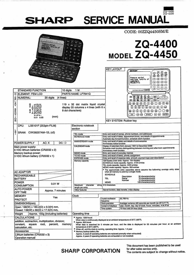
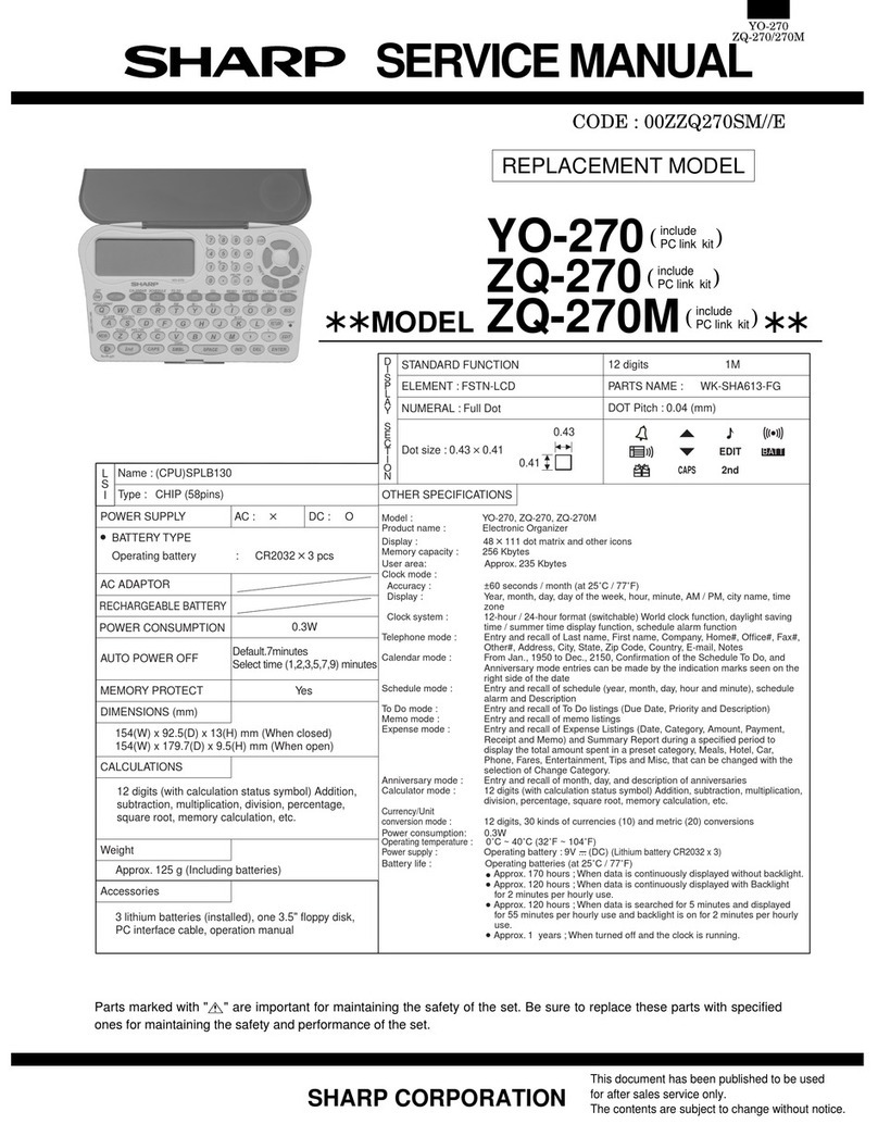
Sharp ZQ-4450M User manual

SHARP
SERVICE
MANUAL
eee
CODE:
00ZZQ4450MSPE
mopvEL
ZQ-4450M
KEY
LAYOUT
@OADES
&
&@
&
na@ae®
eapesnesre®)
oa@ae
4lisnes
X
2@colonnes
Bacolome
X
4rishe
STANDARD
FUNCTION
10digit
iM
ELEMENT:
FEMLCD
PARTS
NAME:
LF7841Q
NUMERAL:
|
20
digits
(4
lines)
|
3
77
119
x
32
dot
matrix
liquid
crystal
342
display
20
columns
x
4
lines
(with
6
x
t
47
@
1g
8
dot
eereciers)
al
be
—
0.51
0.03
(mm)
ABBPEHOBOS
2WOOWVAN
WHO)
@
(SPACE)
(wa)
(oa)
(ENTER)
KEY
SYSTEM:
Rubber
key
Z0-—AOMM
<P
vMH—o
Electronic
notebook
section
PEL
mode
Entry
and
recall
of
names,
phone
numbers,
and
addresses
Entry
and
recall
of
dates,
appointment
times,
and
details
of
appointments
Automatic
day-forward
function,
schedule
alarm
function
Anniversary
notice
function
CALENDAR
mode
Display
of
calendars
from
January
1901
to
December
2099
Anniversary
mark
function
MEMO
mode
[Entry
and
recall
ofeverydaymemos
FTODOmode_[Entryandrecall
ofitems,
priority
assignment
EXPENSE
mode
|
Entry
and
recall
of
expense
date,
amount,
payment
type
and
description
Memory
capacity
128
Kbytes
(User
area:
Approx.
126
Kbytes)
SCHEDULE
mode
capacity:
Approx.
2120
entries
|
TEL
mode
capacity:
Approx.
3400
entries
MEMO
mode
capacity:
Approx.
950
entries
®
The
approximate
entry
capacities
above
assume
the
following
average
entry
sizes
when
all
memory
is
used
by
a
single
mode.
CPU:
—LI3510A
(253pin-FILM)
—Oi-
SRAM:
M5M51008AFP-10LL
(X1)
POWER
SUPPLY
Main
power
supply:
6
VDC
lithium
batteries
(CR2032
x
2)
Memory
backup
power:
3
VDC
lithium
battery
(CR2032
x
1)
AGADAPTOR
[oo
SCHEDULE
REC
HARGEABLE
Description
32
characters/entry
BATTERY
TEL
Name
16
characters/entry
Number
12
characters/entry
POWER
0.01
W
MEMO
128
characters/entry
length
per
entry
AUTO
POWER
Approx.
7
minutes
Secret
function,
data
transfer,
index
display
OFF
TIME
|
MEMORY
|
|
Yes
PROTECT
DIMENSIONS(mrm)
Open:
138(W)
x
160.2(D)
x
9.3(H)
mm.
Closed:
138(W)
x
80(D)
x
17.5(H)
mm.
Weight
|
Approx.
155g
(including
batteries)
__[
Operating
time
CALCULATIONS
|
®
Approx.
1200
hours
_laddition.
subtraction,
multiplication
division:
When
data
is
continuously
displayed
at
an
ambient
temperature
of
20°C
(68°F).
®
Approx.
800
hours
constant,
square
root,
percent,
memory
When
data
is
searched
for
5
minutes
per
hour,
and
the
data
is
displayed
for
55
minutes
per
hour,
at
an
ambient
calculation,
etc.
temperature
of
20°C
(68°F).
Accessories
®
When
off,
and
the
clock
is
running,
operating
time:
Approx.
1.5
year
Lithium
batteries
(CR2032
x
3)
®
Memory
backup
battery
life:
Operation
manual
s+
llaR
EE
frequency
[Clock
precision
|
Average
variance
#60
seconds
permonth
(at25°C/77"F)
Content
of
displays
_|year,
month,
day,
day
of
week,
hours,
minutes,
AMJP-M.
|
[Time
system
=|
12-hour
and
24-hour
clock
Approx.
5
years
(if
operating
batteries
are
replaced
promptly
when
exhausted)
Approx.
3
years
(if
operating
batteries
are
exhausted
or
not
instalied)
This
document
has
been
published
to
be
used
for
after
sales
service
only.
SH
ARP
CORPO
RATION
The
contents
are
subject
to
change
without
notice.

|
|
ZQ-4450M.
1.
SYSTEM
CONFIGURATION
}Q-8000
series
ih
(Excluding
|Q-8900
series)
|
IQ-7000
series
i
ZQ-6000
series
Communication
cable
CE-300L/200L
om
o>
ZQ-5000
series
|
fal
CG
Bo
ch
HIN)
CO
ZQ-4000
series
|
easae
am
OBES
ZQ-3000
series
ae
ZQ-2000
series
Prepare
aarket
pees
reports
of
;
set
3
Communication
cable
CE-220T
ZQ-1000series
EL-6100/61706/6190
EL-6260
COICO
OCIGOOO
RE
RAR
OCU
IRS
ORGANIZER
LINK
(CE-390
Version
1.1)
Personal
Computer

ZQ~4450M
2.
HARDWARE
DESCRIPTION
1.CPU
(LI3510A)
terminal
description
Signat
|
|.
|
Sie
oe,
fie
Signa
Terminal
name
Terminal
name
Bag
|
Signal
|AD5
|
©
|
Address
output
$20
|
©
|Segmentoutput
[sso
|
oO
|
Segment
output
eo
a
Ck
CN
ae
ee
[sto
| 0
|Stobe
output
[ADS]
©
adress
output
's22
|
0
[Segmentoutput
|s82
|
0
|
Segment
output
ISTB1
|
©
|Strobeoutput
‘AD2
|
©
|Addressoutput
|O
|Segmentoutput
[sas
Segment
output
Siac
TOTO
IROL
a
a
Oe
Serr
Strobe
output
_
{E01
Output
port
_
Buzzer
oul
STB6
|
O
|Strobeoutput
Kia.
|
[Keyi
rhino
sTa7_|
©
[Strobeouput
|i”
|
1
|nputpon
“YS
[seo
_|
©
|svobeoupat
[40UT
|
© |
Gockoutput
S
Crystal
oscillation
output
DXi]
1
ive
eaten
input
Strobe
output
lvD_
|__|
Crystal
oscillation
power
source
[STB18
|
O
[strobe
output
~———__.
LCD
drive
power
source
RESET
|
1
[Resetinput
[van
|
iKeyinpwt
iV
|
Keyinpat_
iH
Keyinpat
dN
er
iG
Set
Segment
output
Segment
output
Segment
output
Segment
output
Segment
output
Segment
output
Segment
output
Segmentoutput
_
Segment
outout
Segmentoutput
Scanoncaear
Segment
output
Segment
output
Segment
output
Segment
output
Segment
output
Segment
output
Segment
output
Segment
output
Segment
output
Segment
output
Segment
output
Segment
output
Segment
output
Segment
output
Segment
output
Segment
output
©
|
Segment
output
Segment
output
0
©
|
Segment
output
Segment
output:
S67
S86
S01
Segmentoutput
Segment
output
S25
S26
S27
$31
$32
$93
$34
$94
7
Segment
output
Segmentoutput
_|s9
Segmentoutput
[se
S
,
i<e)
on
7
iv)
Segment
output
_
Segment
output
Segment
output
Segment
output
|
S114,
S43
asf
af
a
|
ou
O};—)/M)]o@
Segment
output
Common
output
Common
output
|
S40
S41
$42
44
45
.
46
$s
S
Key
input
i
KI9
KI
KI5
Ki4
KI3
Ki2
Kt1
aA
@
<
=)
ae]
c
wr
10
D107
[VO
[baa
(IO
(0
[DetaiO
HS
Daa
ide
pica
|
WO
(0
rere
alsalslelajelte
f)
—
ok
to
Common
output
Common
output
Common
output
“een
5)3/8
Segment
output
:
Segment
output
S49
S51
sso
S54
S56
O
o
S
g
M)}H)1a|o
ee
ee
ee
ee
Pe
ee
ee ee
COIN
|
Oia
Common
output
Segment
output
Segment
output
CE3__|
©
|
Chip
enable
output
(Commonoutput__——~S=«iSS
Segment
output
alt
Common
output
_
S60
FO
|Segmentoutput——*ds
[0
|Bankaddressoutput_|S2
|
0
|Segmentouput——+(se2
(0
[Bankaddress
ouput
[s2
|
0
|Segmentouiput
BA06
|
0
[Bankadéress
output
_|S¢
|
©
|Segmentoutput”
[Se
BA0s
|
O
[Bankadéress
output
[85
|
0
|Segmentoutput
Baod
|
0
|Bankaderesscutput_|s6
|
0
[Segmentoutput
0
|Banikaddress
ouput
|s7
|
S67
Ee
co
Chip
enable
output
"O"|Seqmentoutput
[oO
|seqmentoutput
Segment
output
Segment
output
Common
output
Common
output
—
Common
output
Common
output
w
—k
—
©
8
sh
th
©
Segment
output
BA08
H33
H17
Hi8
H19
H20
H21
ro]
oO
“I
Common
output
Common
output
Common
output
2lelololo
Segment
output
83)
>
OQ
wo
ly
Oo
oO
Segment
output,
|
22
i
Bank
address
output
Segment
output
$68
ESS
|
eed
Bankaddressoutput__|S9_
|
O
|Segmentouput
|
S69
Ren
eee
oO
|
Eos
|
|
|Segme
|©
|Segmentoutput
|
Segmentoutput_
_——__|s70__
|
0
|Segmentoutput
|
Oo
|
0
foal
Oo
|
Common
output.
Common
output
AD15
|
O
|
Address
output
AD14_
|
O
|
Address
output
AD13_
|
O
|
Address
output
rs
Segment
output
S71
Segment
output
12
Segment
output
$72
Segment
output
Address
output
O.4
cea
Segment
output
$73
Segment
output
H
OF
Address
output
$14
Oe
Segment
output
S74
Segment
output
ey
Address
output
isis
— |
0
|
Segment
output
1875
OO]
>|
>
0
0
[Adsressoutput
[S16
|
0
|Segmentouipat————*(ST
TO
[Adéressoutput
[S17
| 0
|Segmentoutput
=?
0
[Adéress
output
[818
|
0
|Segmentouiput
|
878
(0
[adcress
output
[819
[0
[Segmentouiput___
[78
=
122
H23
H24
H25
H26
H27
28
H31
H32
”
Oo}
@O
AD9
AD8
AD7
AD6
>|
>|
>
Slo
to
=
{rp
~*

ZQ~4450M
2.
Regulator
(Internal
block
diagram)
3.
Detector
(internal
block
diagram)
\
VDD.
4.
Low
voltage
detection
method
*
In
this
model,
a
warning
is
given
only
to
the
main
battery
exhaus-
tion,
not
given
to
the
backup
battery
exhaustion.
The
main
battery
exhaustion
is
detected
in
the
circuit
shown
below:
EO1
-
KiB
(Nch
open-daqin
type)
-
GND
1)
Caution
level
(detection
voltage:
About
4:8
~
5.3V)
_
¢
When
the
caution
level
is
detected
while
displaying,
the
low
battery
symbol
([BATT])
is
lighted.
¢
When
the
caution
level
is
detected
on
supplying
the
power
to
the
set
or
on
pressing
the
reset
switch,
the
battery
replacement
indica-
tion
(PLEASE
REPLACE
THE
OPERATING
BATTERY
})
is
dis-
played
for
about
4
sec.
*
When
the
caution
level
is
detected
while
sounding
the
alarm
or
key
input
sound,
the
alarm
sound
or
key
input
sound
is
stopped.
2)
Fatal
level
(Detection
voltage:
About
4.4
~
4.8V)
¢
When
the
fatal
level
is
detected
while
displaying,
the
whole
system
is
turned
off.
|
¢
When
the
fatal
level
is
detected, on
supplying
the
power
to
the
set
or
on
pressing
the
reset
switch,
the
whole
system
is
turned
off.
*
When
the
fatal
level
is
detected
while
sounding
the
alarm
sound
or.
key
input
sound,
the
alarm
sound
or
key
input
sound
is
immedi-
ately
stopped.
After
100ms,
the
voltage
is
restored
and
the
next
process
is
performed.
¢
When
the
fatal
level
is
detected
while
the
power
is
off,
pressing
the
[ON]
key
will
not
supply
power
to
the
set.
The
reset
key
is
also
disabled.
(Until
the
battery
is
replaced.)
[Note]
Since
low
voltage
detection
is
not
performed
for
the
memory
protection
battery,
please
note
the
battery
replacement
label
and
replace
when
necessary.
5.
Alphabet:
Caps/Low
*
Caps/Low
of
alphabet
can
be
selected
by
pressing
the
key.
¢
When
the
power
is
supplied
by
pressing
the
|
ON]
[ON]
key,
Caps
is
selected.
(Caps
symbol
is
lighted.)
@
Circuit
*
This
circuit
has
no
hysteresis
characteristics.
VCC
-
OUT
EO1
@
Software
1.
Caution
level
is
detected
every
0.5sec.
(EO1
=
GND)
2.
In
normal
cases,
only
the
fatal
level
is
detected.
(EO1
=
Vcc)
_3.
Even
when
the
system
is
off,
the
fatal
level
is
detected.

~
6.
Memory
map
|
“|
SYSTEM
AREA:
{
USER
AREA
|
(82KB).
“os
cE1
S2KByte
64KByte
128KByte
(82KB)
So
Neti
Bye
ee
ae
fee
0000}
SYSTEM.
~
Ieee
(32KB)
1}
(32KB)
USER
AREA
BAIG
(128KB)
10000H
(32KB)
1FFFF
L
(32KB)
1FFFFH
3.
NOTE
FOR
SERVICING
1.
Current
check
(VCC
=
6.0V).
1.
Press
the
OFF
key.
2.
Measure
the
current
value.
(After
1
sec.)
When
OFF:
4
5A
or
less
3.
Press
the
ON
key.
4.
Measure
the
current
value.
When
ON:
50mA
or
less
2.
Note
for
Battery
replacement
(1)
Replacing
batteries
|
Batteries
used
|
in
the
Organizer:
ype
Wedel
ys
Lithium
battery
oR2032
|
2
|
Unitoperation
|
Lithium
battery
CR2032
Memory
backup
_
The
standard
built-in
clock
is
powered
by
the
operating
batteries.
ZQ=4450M
(2)
Precautions
when
replacing
the
batteries.
Before
replacing
the
battery,
be
sure
to
press
[OFF]
to
turn
the
power
off:
|
Do
not
replace
the
memory
backup
battery
when
the
operating
bat-
teries
are
depleted.
When
the
operating
batteries
become
weak
and
you
turn
the
power
on,
"[EZJ##
"
will
be
displayed
and
the
following
display
will
appear
temporarily:
Tenees
REPLACE
THE
_
OPERATING
BATTERIES!
lf
the
batteries
become
weaker
{the
alarm
or
the
Key
beep
does
not
sound),
the
power
may
go
off
during
operation
or
the
Organizer
may
—
fail
to
turn
on.
|
The
memory
contents
will
still
be
retained
by
the
memory
backup
battery.
Replace
the
operating
batteries
to.
avoid
loss
or
alteration
of
data.
Before
removing
the
batteries
for
replacement,
record
important
infor-
mation
on
paper.
.
(3)
Battery
replacing
procedure
@
Remove
the
battery
cover.
1)
Loosen
screw.
2)
Remove
battery
cover.
(Note)
Screw
is
so
constructed
as
not
to
be
removed
for
preven-
tion
against
missing.
m@
Remove
the
battery.
Caution
label
3)
Remove
caution
label.
-
4)
Remove
the
battery.
(MAIN
side)

ZQ-4450M
Caution
—
fabel
5)
Remove
caution
label.
6)
Remove
the
screw.
7)
Remove
battery
protect,
and
remove
the
battery.
(Backup
side)
(Note)
There
is
a
screw
beneath
battery
protect.
When
removing
the
keyboard
lower
cabinet,
battery
protect
must
be
removed.
3.
Using
the
data
transfer
function
This
Organizer
can
transfer
data
to
and
from
the
following
models.
*
Other
ZQ-4450
Organizers
using
the
optional
CE-200L
or
CE-300L
cable.
*
The
1Q-8000,
!1Q-7000,
ZOQ-
5000,
ZQ-3000,
ZQ-2000
and
Z0-
6000
series
Organizers
using
the
optional
CE-200L
or
CE-300L
cable.
*
The
ZQ-1000,
EL-6100
series
and
EL-6260
Organizers
(including
Auto
Dialer)
using
the
optional
CE-220T
cable.
Transferable
data
varies
according
to
the
model
connected
to
the
Organizer.
SCHEDULE
ZQ-5000
series
10-8400
Yes
Yes
|.
.Y
ZQ-2000
ali
models
only)
70-4450
Ve
~
70-3050/Z20-3250
°
seal]
epee
——[
ea
ear
LBiddseres
|
ves
[Wes|
—
|
—
|=
|
—
cv
|=,
[wl
st
-
|
—-.|
|
There
may
be
some
data
transfer
restrictions
between
these
models.
_
Before
connecting
the
cable
and
transferring
data
between
Or-
‘
ganizers,
turn
off
both
units.
Transferable
data
Model
connected
to
the
ZQ-4450
1Q-8000
series
10-7000
series
(10-8500M,
Notes:
©
To
interrupt
data
transfer,
press
.
¢
Ita
connector
is
disconnected,
or
a
similar
problem
occurs
during
data
transfer,
the
message
"I/O
DEVICE
ERROR?"
will
appear.
Press
[C.CE]
to
clear
the
error.
e
After
data
transfer,
the
data
on
the
transmitter
is
preserved.
*
There
may
be
a
voltage
level
difference
between
the
connecied
Organizers
which
may
cause
the
display
contrasts
to
change.
Should
this
occur,
readjust
the
contrast
as
required.
(1)
Transferring
data
between
ZQ-4450
Organizers
Data
in
the
SCHEDULE,
ANNIVERSARY,
TEL,
MEMO,
TO
DO
and
EXPENSE
modes
can
be
transferred.
The
data
is
transferred
and
verified
by
mode
(all
entries
in
a
mode
or
a
directory
—
TEL
1,
TEL
2,
TEL
3)
or
by
entry.
In
addition,
data
can
be
backed
up.
@
Transferring
data
by
mode
or
by
entry
During
mode
transfer,
data
previously
stored
in
the
specified
mode
of
the
receiver
are
deleted.
Proceed
with
caution.
Note:
When
mode
transfer
is
carried
out
in
the
TEL
mode,
all
listings
in
the
specified
directory
will
be
transferred.
(in
this
case,
the
directory
file
name
is
transferred
at
the
same
time.)
1.
Select
the
mode
on
the
transmitter
and
receiver.
SCHEDULE
(Transmitter)
SCHEDULE}
(Receiver)
2.
Select
the
data
transfer
function
on
the
receiver.
3.
Select"
RECEIVE"
to
set
the
unit
in
the
receive
mode.
2
<UNIT
TO
UNIT>
RECEIVING
MODE
4,
Select
the
data
transfer
function
on
the
transmitter.
Note:
To
transfer
a
single
entry
display
the
desired
entry
and
press
[OPTION].
5.
Select"
BJ
SEND"
to
transter
data.
f
Notes:
®
if
the
mode
of
the
transmitter
and
the
mode
of
the
receiver
are
not
the
same,
data
transfer
is
not
established.
The
message
"DATA
ERROR’
is
displayed.
When
transferring
TEL
data,
directories
on
the
transmitter
and
receiver
can
be
different.
The
contents
received
by
the
receiver
will
be
stored
in
the
open
directory.
For
example,
if
TEL
1
is
selected
on
the
transmitter
and
TEL
3
on
the
receiver
before
the.
data
transfer
is
established,
the
contents
of
TEL
1
will
be
sent
to
and
stored
in
TEL
3.
©
Turn
off
the
SECRET
function
on
both
the
transmitter
and
the
receiver
before
mode
transfer.
2
®
|f
the
amount
of
memory
available
on
the
receiver
at
the
time
of
transfer
is
insufficient,
data
transfer
is
not.
‘possible:
‘The
message
"MEMORY
FULL"
appears.
Delete
any
unnecessary
data,
verify
.
whether
the
available
memory
is
sufficient,
and
repeat
the
data
-
transfer
procedure.
|
*
Ifan
error
message
appears
while
transferring
data,
press
[
to
clear
the
error.
:

@
Transferring
backup
data.
All
the
contents
of
the
Organizer
are
transferred.
During
backup
data
transfer,
data
stored
on
the
receiver
are
deleted.
Proceed
with
cau-
tion.
(Backup
data
transfer
is
only
possible
between
identical
products.)
_
1.
Select
the
data
transfer
function
on
the
receiver
and
set
it
in
the
receive
mode
for
backup
data
transfer.
[and]
2
<UNIT
TO
UNIT>
BACKUP
RECEIVING
MODE
2.
Select
the
data
transfer
function
on
the
transmitter
and
Baro
backup
data
transfer.
[2nd]
[OPTION]
[2nd]
1
@
Verifying
data
it
is
possible
to
verify
data
by
mode
or
by
entry.
If
any
discrepancies
are
found,
the
message
"VERIFY
ERROR"
is
displayed.
Verify
data
in
the
SCHEDULE
mode.
1.
Select
the
mode
on
the
transmitter
and
the
receiver.
SCHEDULE
(Transmitter)
SCHEDULE]
(Receiver)
2.
Set
the
receiver
in
the
verify
mode.
:
a
3
<UNIT
TO
UNIT>
-VERIFYING-
3.
Select
the
data
transfer
function
on
the
transmitter.
OPTION
Note:
To
verify
an
entry,
display
the
entry
to
be
verified
and
press
4.
Perform
verification.
1
(2)
Transferring
data
with
another
ZQ
series
or
IQ
series
Organizer
@®
Data
transfer
restrictions
There
aré
some
restrictions
when
transferring
data
with
any
ZQ
series
Organizer
other
than
the
ZQ-4450
or
the
IQ
series
Organizers
(previously
shown).
These
restrictions
result
from
differences
in
func-
tions
and
the
maximum
allowable
size
of
an
entry
between
the
Or-
ganizers.
@®
When
transferring
SCHEDULE
data
from
ZQ-6000
series,
1Q-8000,
IQ-7000
or
ZQ-5000
series
Organizers
®
Any
alarms
set
on
SCHEDULE
data
transferred
from
the
ZQ-6000,
ZQ-8000,
|Q-7000
or
ZQ-5000
series.
Organizers,
regardiess
of
their
precise
setting
time
for
specific
event,
will
be
set
to
the
event's
starting
time
on
thé
ZQ-4450.
ZQ-4450M
@
When
transferring
data
from
ZQ-6000
or
IQ-8000
series
Organizers
j
®
When
transferring
an
entry
from
the
ZQ-6000
or !Q-
8000
series
to
the
ZQ-4450,
the
maximum
allowable
size
of
the
transferred
entry
is
as
follows:
TEL
mode:
537
characters
SCHEDULE
mode:
523
characters
MEMO:
mode:
544
characters
TO
DO
mode:
530
characters
lf
an
entry
exceeding
these
limits
is
sent
to
the
ZQ-4450,
"/0.
DEVICE
ERROR?"
appears
and
the
transfer
will
not
be
successful.
The
maximum
number
of
characters
that
can
be
edited
after
an
entry
is
transferred
to
the
ZQ-4450
is
514
in
the
TEL
mode
and
512
in
the
SCHEDULE,
MEMO
and
TO
DO
modes.
Entries
ex-
ceeding
these
limits
can
be
displayed
but
cannot
be
edited.
Those
exceeding
515
characters
can
neither
be
displayed
nor
edited.
®
Mode
transfers
from
the
ZQ-6000
series
and
1Q-8000
series
can
be
performed
even
when
the
maximum
length
of
an
entry
exceeds
the
character
limits
specified
above.
However,
to.
display
and
edit
data,
the
number
of
characters
must
be
within
these
limits.
e
TEL
free
field
contents
can
be
received
and
displayed
on
the
ZQ-4450,
but
are
deleted
once
the
edit
mode
is
entered.
@
When
transferring
TO
DO
data
from
ZQ-6000
series,
1Q-8500M
or
1Q-8400
Organizers
*
When
a
TO
DO
entry
is
transferred
from
the
ZQ-6000
series
or
1Q-8500M/IQ-8400
to
the
ZQ-4450,
the
contents
of
the
date
and
category
fields
are
deleted
and
only
the
contents
of
the
description
and
priority
fields
are
received.
¢
When
transferring
TO
DO
data
by
mode
from
the
ZQ-6000
series
or
1Q-8500M/IQ-8400
to
the
ZQ-4450,
entries
are
stored
in
the
ZQ-4450
without
date
or
category
field
contents.
If
the
transferred
data
includes
an
entry
with
a
date,
the
priority
of
all
transferred
entries
will
be
a
space.
The
contents
of
the
priority
field
are
received
correctly
only
when
none
of
the
transferred
entries
con-
tain
a
date.
°
No
data
verification
can
be
carried
out.
|
©
When
transferring
data
to
and
from
ZQ-1000
series
Organizers
®
Ail
characters
transferred
from
the
ZQ-4450.are
displayed
in
capi-
tal
letters
on
the
ZQ-1000
series.
Characters
and
symbols
that
cannot
be
displayed
on
the
ZQ-100
series
appear
as
"me".
°
EXPENSE
data
transferred
between
the
ZQ-4450
and
the
ZQ-
1000
series
is
stored
on
the
receiving
unit
without
payment
type
data.
¢
When
transferring
EXPENSE
data
by
mode
from
the
ZQ-1000
series
to
the
ZQ-4450,
an
"I/O
DEVICE
ERROR"
may
occur.
This
will
occur
when
there
is
not
enough
memory
space
to
be
assigned
as
payment
type
data
area,
which
EXPENSE
data
from
the
ZQ-
1000
series
does
not
have.
If
the
error
occurs,
delete
unnecessary
data
on
the
ZQ-4450
to
increase
free
memory,
then
transfer
the
data
again.
Once
an
"I/O
DEVICE
ERROR"
occurs,
all
EXPENSE
data
transferred
to
the
ZQ-4450
before
the
error
is
cleared.
e
When
transferring
EXPENSE
data
by
mode
from
the
ZQ-1000
series
to
the
ZQ-4450,
no
data
verification
can
be
carried
out.
©
Transferring
data
by
mode
or
by
entry
Transfer
the
"ABC
BANK"
memo
stored
in
the
Organizer.
4.
Recall
the
memo
to
be
transferred
on
the
transmitter.
Note:
To
perform
mode
transfer,
select
the
mode
by
pressing
the
mode
key,
and
then
press
|C-CE].
It
is
not
necessary
to
display
an
entry.

ZQ-AA50M
2.
Select.the
data
transfer
function
on.the
receiver,
and
set
it
in
the
receive
mode.
3.
Select
the
data
transfer
function
on
the
transmitter
and
perform
data
transfer.
[2nd]
[OPTION]
14
Notes:
¢
Follow
the
same
steps
to
transfer
data
from
another
ZO
or
an
IQ
series
Organizer.
°¢
Notes
described
on
page
4
also
apply
here.
®
When
transferring
data
to/from
another
ZQ
series
or
an
IQ
series
Organizer,
the.
display
contrast
of
the
ZQ-4450
Sigenizer
decrease
when
the
units
are
connected.
:
@
Verification
Follow
the
steps
explained
in
"Transferring
data
between
ZQ-4450
Organizers"
above.
(3)
Transferring
data
with
an
EL
series
Organizer
(including
Auto
Dialer)
For
the
EL-6100
series
Organizer,
TEL
data
and
SCHEDULE
data
can
be
transferred.
For
the
EL-
6260
Auto
Dialer,
TEL
data
can
be
transferred,
Data
is
transferred
by
mode
or
by
entry.
@
Data
transfer
restrictions
.
When
transferring
data
with
an
EL
series
Organizer
(including
the
Auto
Dialer),
the
following
restrictions
apply:
@)
When
transferring
data
to
an
EL
series
Organizer
®
Transferred
data
is
added
to
previously
stored
data.
*
Data
is
transferred
in
the
same
mode
and
directory.
°
If
a
transferred
entry
exceeds
the
maximum
number
of
characters
that
can
be
entered
into
the
EL
series
Organizer
as
one
entry,
excess
characters
are
deleted.
®
Characters
and
symbols
that
cannot
be
displayed
on
the
EL
series
Organizer
are
replaced
by
spaces.
If
all
the
columns
that
can
be
displayed
are
replaced
by
spaces,
the
corrésponding
entry
is
not
stored.
*
All
letters
are
converted
to
capital
letters
on
the
EL
series
Or-
ganizer.
*
If
the
SECRET
function
is
turned
on
in
the
ZQ-4450,
sri
non-
secret
data
can
be
transferred.
@
When
transferring
data
from
an
EL
series
Organizer
*
The
received
data
are
added
to
previously
stored
daia.
°
All
non-English
characters
are
converted
to
small
letters.
®
if
the
SECRET
function
is
turned
on
in
the
EL
seriés
Organizer,
only
non-secret
data
can
be
transferred.
@
Transferring
data
to
an
EL
series
Organizer
—
Transfer
all
TEL
1
data
in
the
Organizer
to
TEL
1
in
the
EL
series
Organizer.
1.
Set
the
receiver
in
the
receive
mode.
2.
Select
the
mode
on
the
transmitter.
TEL
(Select
the
desired
directory.)
3.
ee
the
bled
transfer
function
on
the
transmitter.
rants
To
transfer
an
entry,
display
the
entry
to
be
transferred
and
press
[2nd]
[OPTION].
4.
Perform
data
transfer.
1
;
*
If
the
amount
of
memory
available
in
the
receiver
at
the
time
of
data
transfer
is
insufficient,
an
error
message
appears.
Delete
any
unnecessary
data,
verify
that
there
is
sufficient
memory
available,
and
repeat
the
procedure.
©
Transferring
data
from
an
EL
series
Organizer
1.
Select
the
mode
on
the
receiver.
2.
Select
the
data
transfer
function
on
the
receiver,
and
set
it
in
the
receive
mode.
3
Perform
data
transfer
from
the
transmitter.
(4)
Exchanging
data
with
a
personal
computer
With
Sharp's
Organizer
Link
software
and
cable
package,
you
can
exchange
data
with
a
personal
computer.
The
link
is
made
via
the
4-pin
computer-link
port
on
the
left
side
of
the
Organizer
using
an
interface
cable
to
suit
your
computer.
See
the
Organizer
Link
manual
for
connection
and
software
operating
details.
Note:
Sharp’s
Organizer
Link
software
may
not
be
available
at
the
time
you
purchase
this
Organizer.
Check
with
your
local
Sharp
dealer
concerning
availability.
4.
Reset
procedure
(1)
When
trouble
occurs
An
impact
or
a
strong
external
electrical
field
may
leave
none
of
the
keys
operational.
Press
the
RESET
switch
on
the
back
of
the
Or-
ganizer.
The
impact
or
external
electrical
field
may
erase
some
or
all
of
the
Organizer’s
memory.
Press
the
RESET
switch
with
the
tip
of
a
ball-point
pen
or
similar
object,
but
not
anything
breakable
(like
a
pencil
point
or
a
needle).

(2)
All
RESET
operation
If
a
problem
occurs
after
replacing
the
batteries,
or
if
the
Organizer
does
not
function
properly
even
after
the
above
RESET
operation,
perform
the
following:
1.
While
holding
[ON],
press
the
RESET
switch
on
the
back.
Release
the
RESET
switch
and
then
release
[ON].
The
following
dispiay
will
appear.
CLEAR
ALL
DATA
"2.
Press
[N.
Returns
to
the
initial
display.
Caution:
Do
not
press
in
step
2.
Pressing
will
delete
all
data
stored
in
the
Organizer
and
reset
the
built-in
clock.
|
5.
Contrast
adjustment
Adjust
the
display
contrast
to
make
the
display
easier
to
read.
1.
Press
[2nd]
[FUNCTION].
<
FUNCTION
>
MEMORY
CHK
LCD
El
DATA
DEL
L
2.
Select
"2
LCD
CONT”,
2
3.
Press
[a]
or
['¥]
to
darken
or
lighten
the
display
as
required.
The
amount
of
contrast
will
change
continuously
when
either
or
is
held.
4.
After
adjusting
the
contrast,
press
[C-CE].
6.
Turning
the
"beep"
on
and
Off
While"
\
"
is
displayed,
a
"beep"
will
sound
when
a
key
is
pressed.
To
turn
the
"beep"
on
and
off,
press
.
The
"beep"
will
not
sound
after"
JS
“
goes
off.
To
turn
the
“beep”
back
on,
“
repeat
the
process.
Note:
When
entering
the
diag
mode,
user's
data
will
be
destroyed.
|
B
ZQ-4450M
4.
DIAGNOSTICS
1.
Entering
Diag
mode
Keep
pressing
ON
+
D
keys
and
reset
the
machine,
and
the
DIAG
menu
display
shown
below
will
appear.
Pressing
0
cancels
DIAG
and
returns
to
TEL
1
mode.
_
Pressing
1
starts
the
LCD
check
program.
Pressing
2
starts
the
PCB
check
(RAM
check)
program.
Pressing
3
starts
the
production
process
check
program.
Pressing
4
starts
the
static
electricity
check
program.
Pressing
5
starts
the
intermittent
aging
program.
Pressing
6
starts
the
low
battery
check
program.
Pressing
7
starts
the
safety
standard
system
communication
pro-
gram.
Pressing
9
turns
OFF
normally.
LCD
EF
PTAGING
PCB
G
Le
SET
EMI
@
Esp
@
Sure
to
back
up
the
necessary
data
before
entering
the
diag
mode.
”
2.
Diag
contents
(1)
When
LCD
is
selected:
I.
A
frame
is
displayed
in
one
dot
width
around
the
outer
peripheral
of
the
LCD.
(Pressing
the
Enter
key
goes
to
the
next
screen.)
II.
Zigzag
pattern
1
is
displayed.
(Pressing
the
Enter
key
goes
to
the
next
screen.)
iI.
Zigzag
pattern
2
is
displayed.
(Pressing
the
Enter
key
goes
to
the
next
screen.)
IV.
The
vertical
line
pattern
is
displayed.
(Pressing
the
Enter
key
goes
to
the
next
screen.)
V.
The
horizontal
line
pattern
is
displayed.
(Pressing
the
Enter
key
goes
to
the
LCD
density
control
check
screen.)
During
displaying
of
the
LCD
check
in
I
to
V,
the
density
control
can
be
performed
with
&
and
W
keys.
If
possible,
the
most
appropriate
density
is
automatically
performed
for
each
screen.
In
the
case
of
IT
and
IV,
the
following
symbol
will
light.
30:
31:
EDIT
2nd
CAPS
*
i
Td
In
the
case
of
ITI
and
V,
the
following
symbols
will
light.
.
The
LCD
density
control
check
is
performed.
(Pressing
the
Enter
key
goes
to
the
menu
display
screen.)
After
displaying
the
horizontal
pattern,
the
LCD
density
is
auto-
matically
adjusted:
|

ZQ-4450M
(2)
When
PCB
is
selected:
Wiring
of
(1)
RAM
is
checked,
and
WRITE/READ
of
(2)
A5h
and
(3)
5Ah
are
performed
for
the
whole
RAM
area
to
perform
the
RAM
bit
failure
check.
After
checking,
the
RAM
capacity
is
displayed.
In
case
of
an
NG,
the
check
where
the
NG
occurred
is
also
displayed.
However,
an
error
may
caused
by
the
defective
device.
During
checking
End
of
Checking
(Normal)
RAM
128K
OK
__
End
of
Checking
(NG)
TRAM128K1.—CNG
When
the
check
is
completed
normally,
press
the
Enter
key
to
return
to
the
menu
display
screen.
In
case
of
an
error,
press
2nd
+
CCE
keys
to
return.
|
(3)
When
SET
is
selected:
This
item
is
for
production
process
test,
and
is
not
required
for
servic-
ing.
(4)
When
ESD
is
selected:
This
item
is
for
production
process
test,
and
is
not
required
for
servic-
ing.
(5)
When
PT
AGING
is
selected:
The
following
procedures
II
to
IV
are
repeated
without
stop.
To
ter-
minate,
press
the
RESET
key.
When
the
battery
voltage
falls
under
the
CAUTION
level,
set
the
communication
output
port
to
HIGH,
During
this
procedure,
even
during
displaying,
the
machine
operates
at
the
full
power.
I.
A5h
is
written
to
the
whole
area
of
RAM.
II.
The
zigzag
display
is
shown
for
2
sec,
and
thé
reversed
display
is
shown
for
2
sec,
III.
The
value
written
in
the
RAM
is
checked.
At
that
time,
the
reversed
zigzag
display
is
kept.
RAM
32
Kbyte,
about
1.1
sec
.
RAM
64
Kbyte,
about
2:1'sec
RAM
128
Kbyte,
about
4.2
sec
RAM
256
Kbyte,
about
8.4
sec
Required
time:
.
The
results
of
the
above
RAM
checks
are
displayed
as
shown
below:
in
normal
procedure,
the
display
is
kept
for
RAM
32
Kbyte,
about
72
sec
RAM
64
Kbyte,
about
92
sec
RAM
128
Kbyte,
about
123
sec
RAM
256
Kbyte,
about
186
sec.
Then
the
operation
goes
to
the
next
step
(under
the
normal
key
waiting
state).
In
case
of
an
error,
the
aging
is
stopped
at
once.
The
rough
ratio
of
the
operation
and
the
key
waiting
state
is
1:
1:5,
Normal
-
RAM
CHK
OK
000013
Error
NG
RAM
CHK
vee
fh
000001
This
figure
shows
the
loop
number.
V.
The
RAM
contents
are
reversed
for
every
100
times
and
the
|
operation
goes
to
step
Il.
(6)
When
LB
is
selected:
I.
The
following
display
is
given
and
the
process
of
the
max.
cur-
rent
is
performed.
II.
When
the
battery
voltage
falls
below
thé
CAUTION
level,
the
following
display
is
given
and
$A
symbol
is
lighted.
LB
CHK
CAUTION
When:
the
battery
voltage
falls
below
the
FATAL
level,
the
opera-
tion
is
turned
off.
Under
this
state,
no
key
is
valid.
To
terminate,
reset
the
machine.
YI.
(7)
When
EMI
is
selected:
This
item
is
for
production
process
test,
and
is
not
required
for
servic-
ing.
:
.

ZQ-4450M
a
wt
NNOBEOONPESSoSE
z
3
Not
mounted
.
:
“4
‘
Th
leery
eae
ween
NEE
SSSSR80055
Bees
iia
Oe
eee.
seal:
BAAeS
BAS
ceG
hit
“art:
satan
ETN
mt
sorta
ORR)
SALA
ole
.’
A
ARAR
A
KARA
eee
NFS
Raver
nennnster
snannmeng
Sai
:
ii
co
R7
Not
installed.
119D0T
*
32D0T
FSTN
ZQ-4450M
Ré6
Installed.
NOTE
:
i
—“evedv_]
-—
Eve
DIAGRAM
6.
PWB
PARTS
SIGNALS
ARRANGEMENT
-10-
a.

DESCRIPTION
-—
O.
Ny,
y
caution
label
press
rubber
rE
{LCD
unit
<
2
@
9°
$1
el
8
Tae
1G]
2)
2)
>|
es]
ee
:
Os
4};
CO)
aw)
:
w
noe
~
ef
‘
;
oO
et
og
OO:
:
x
Oy.
nd
12.
3
oO}
en|
<¢/
<9)
35]
20]
0</n
*
<|<)<¢|n|<|<l<
@ °
.
a
°
*
°
:
¢
P
!
i
LY
ug
PACA
ES
:
4
i
bs
:
an
F5
:
7
"
Suge
ds
t
q
_
4
&
a
Ps
.
ae
,
‘
je
d
:
:
ee
aD
5
ae
.
C3
os
2
:
:
‘
:
Ne:
4
e
E
Ear
‘
tBi:
4
+
*
z.
‘
.
:
.
"
ae
i
.
ra
oi
7
ach
oe
fh
hors:
~
~~
; F
p
.
aad
:
a
:
:
ra
B
S
Hae
f
om
*
f
a
tae
.
sf.
oe
ao
.
:
;
:
ne
'
7
.
i
ie
:
eke
:
baie
?
5
'
:
:
a
ft
2
“fh
ar)
,
we
i
aa
pas
:
:
ae
Bo
de
‘
;
j
ane
bi
he
:
zr
;
2
ees
es
;
;
D
.
i
Hove
g
=e
4
ro
a
+
™
ear
:
bs
o
"
.
a
.
.
:
i»
Hi
.
‘
:
:
5
ew,
ae
;
if
:
j
:
@:,
vl
cessories
A
Tac
|_N_|D_
[Packing
cushion
terial
ing
ma
PARTS
CODE
2]
Pack
i]
Exteriors
CCPS0018
~~
PARTS
GUIDE
Exteriors
—-13-
~
{2-

7Q-4450M
PWB
unit
NO.
|
PARTS
CODE
DESCRIPTION
|
TTTPSHEZ1055PC2zZ
{|
AD
[|
|
C
|Buzzerspacr
«_—
r—(“‘“Cs*™w™~™~™~”CO”TO™O™~—OC“‘RNC‘(C
NC
rT
2IPZETLIO038PCZZ
{
AB
|
|
C
_|PET
reinforcing
tape
rT
3IPZETLI039PCZZ
{|
AA
|__|
C__|{PWB
insulate
sheet
~~
41QCNCM1416CCOD
|
AE
[
|
C
[Connector
(4pin)
rr
—“ss—TC“C(‘CCNNCC
T—SIOTANBIOI19PCZzZ
{|
AE
|
[|
C
([Batteryterminal
Oe
T“6fOTANB1O30PCZ2Z
[|
AC
|
[
C
[Batteryterminalh®
—
—“‘“C;™*w™S™S™S™O.TCO~™OCTC“‘NCis*C
TFTRALMB1030CCZz
[|
AD!
[|
B
[Buzzer(EFB-S49C02P)
=
—“OO————”CC“‘$SNNNCN
LL
TT
BIRC-EZ1O07AECILA
|
AB
|]
{
C
{Capacitor
(LOWV
100uF
[C6
T9IRCRSP1O00S9PCZZ
|
AD
|
|
B
|Crystal(32.768KHz)
——C—COsC(C‘C
XK
‘S'S
rT
WOIVCCCTVIHH130J)
|
AA
|
N
|
C
[Capacitor
(SOWV13PF)
—s———
DT
Tm
"TIVCCCTVIHHi160J)J
|
AA
|
|
C
[Capacitor
(50WV
16PF)
—-—r—C
C—O
SCE
GAY
TW2IVCKYTQIEFI0O5Z
|
AB
|
|
C
[Capacitor(25WV1lOuF)
©
[(C13~15)
|
Tr
w3/VCKYTVICFi05zZ
|
AB
|
[|
C
[Capacitor(16WV10eF)
©.
£620)
|
44IVCOKYTVIEFIO4Z
|
AA
|
|
C
_
{Capacitor
(25WV
0.10uF
7
|
[C5,7~10,18,19]
T15/VHDDAN202U/—1
|
AB
|
[
B
[Diode
(DAN202U).
eT
T
16/VHDDA2Z04U//—-1
|
AB
|
|
B
[Diode
(DA204U)
re
—i(‘“‘i™éOCOOCCLC
T17IVHDRB400D//-1
|
AC
|
|
B
[Diode
(RB400D)
—-—s—sns—
srwrwwwww™~—‘(OCOCT.T.T.}DUN9'—
——™—C*CTC#DY'F
I
fr
IBIVHi
RHSRLZSOAAI
|
AD}
{
B_
JIC
(RH5RL30AAl
LIC6
Tr
19}VHIRHSRLBSBCAA1
|
AD
{|
_[{
B_
[IC
(RHSRL5S0AA1
LIC7
J
rT
2O;/VHIRHSVL40AA1
}
AD
|]
_[{
B_
{IC
(RH5VL40AA1
|
iC8
TO
OTIVHi
HS
LOOSAFPI0
|
BF
|
|
B_}IC
(51008AFP10
LIC5]
To
221VRS-TS2AD00035
|
AA
|
|
C_jResistor
(1/10W
00
+5%
LR6]
T“93I1VRS—-TS2AD105J)
[
AA
|
|
C
jResistor(1/10OW1.0MQ+5%)
—
ERS
8)
|
94}VRS—-TS2AD1235
|
AA
|
|
C__|Resistor
(1/10W
12KQ
+5%
[R4]
T
2/VRS—-TS2AD221J5
|
AA
{|
|
C_
JResistor
(1/10W
2200
+5%
[R18}
|
2@IVRS—-TS2AD332J)
|
AA}
{| C_
[Resistor
(1/10W
3.3KQ
+5%
LR9,10]
o7IVRS-TS2AD4R7J5
|
AA
|
|
C
[Resistor
(i1/lOW
470
+5%)
———(CO:—CC~C‘C«‘*SRR‘A‘CY_CO.
T
28IVRS-~TS2AD471J5
|
AA
|
|
C
[Resistor(1/10W
4700
+5%)
——
—“—s~s*~*s~s~™~:~—”””:””””C™C™~CC‘(CSCS&SR2«YS
99IVRS-TS2AD823/3
|
AA
|
|
C
{Resistor(1/IOWS82KQ+5%)
©
C[R3))
rT
30IVCCCTVIHH222J5
|
AB
|
{|
C__|Capacitor
(50WV
2200PF)
[C21]
Fe
see
tives,
0d
oor
CUD ose
i
ede
et
eee
age
a
ee
ee
ee
ee
ee
a
te
a
epte
b
cae
sie
pe
onda
eaten
T
$OIIDUNTK2048PCZZ
|
BQ
|
|
E
J|MainPWBuntt
7
fee
on
gee
i
ale
oI
es
A
eee
|
cane
pens
enh
ee
et
anh
oe
Pe
ee
tee
a
oe
AM
ee
ee
ee
ete
ee
eg
ee
ee
Ee
oe
Set
ee
Beet
ee
gee
ee
ee
eel
=
Mee
cee
ea,
eh
ee
wpe
n
ae
e
e
e
nee
_captes
bee
Rocuae.
lice
tetecen
cites
tm
Gee
INE
ok
min
tee
oe
eet
et
ee
eg
ge
ee
ci
ee
ee
he
el
CAUTION
FOR
BATTERY
REPLACEMENT
(Danish)
:
ADVARSEL
!
Lithiumbatteri
—
Eksplosionsfare
ved
fejlagtig
handtering.
Udskiftning
ma
kun
ske
med
batteri
af
samme
fabrikat
og
type.
Lever
det
brugte
batteri
tilbage.til
!everandoren.
(English)
Caution
!
Danger
of
explosion
if
battery
is
incorrectly
replaced.
Replace
only
with
the
same
or
equivalent
type
recommended
by
the
equipment
manufacturer.
—
Discard
used
batteries
according
to
manufacturer’s
instructions.
(Finnish)
VAROITUS
Paristo
voi
rajahtaa,
jos
se
on
virheellisesti
asennettu.
'
Vaihda
parisio
ainoastaan
laitevalmistajan
suosittelemaan
tyyppiin.
Havita
kaytetty
paristo
valmistajan
ohjeiden
mukaisesti.
(French)
ATTENTION
ll
y
a
danger
d’explosion
s’
il
y
a
remplacement
incorrect
de
la
batterie.
Remplacer
uniquement
avec
une
batterie
du
méme
type
ou
d’un
type
recommandé
par
le
constructeur.
Mettre
au
rébut
les
batteries
usagées
conformément
aux
instructions
du
fabricant.
(Swedish)
VARNING
|
Explosionsfare
vid
felaktigt
batteribyte.
Anvand
samma
batterityp
eller
en
ekvivalent
typ
som
rekommenderas
av
apparatiillverkaren.
Kassera
anvant
batteri
enligt
fabrikantens
.
instruktion.
244
c
Table of contents
Other Sharp Desktop manuals

Sharp
Sharp PC-1500A User manual

Sharp
Sharp MZ-808 User manual

Sharp
Sharp ZQ-3000 User manual

Sharp
Sharp MZ-80B User manual

Sharp
Sharp MZ-5500 User manual

Sharp
Sharp MZ-5600 User manual

Sharp
Sharp PC-AX40 User manual

Sharp
Sharp MZ-80B User manual

Sharp
Sharp MZ-3500 User manual

Sharp
Sharp SCR3042FB User manual

Sharp
Sharp MZ-80A User manual

Sharp
Sharp ZQ-4400 User manual

Sharp
Sharp PN-TPC1W User manual

Sharp
Sharp MZ-80A User manual
Sharp
Sharp MZ-700 Series User manual

Sharp
Sharp PN-L602B Instruction Manual

Sharp
Sharp MZ-800 User manual

Sharp
Sharp MZ-700 Series User manual

Sharp
Sharp Shuttle PN-SPCi5W7 User manual

Sharp
Sharp MZ-800 User manual