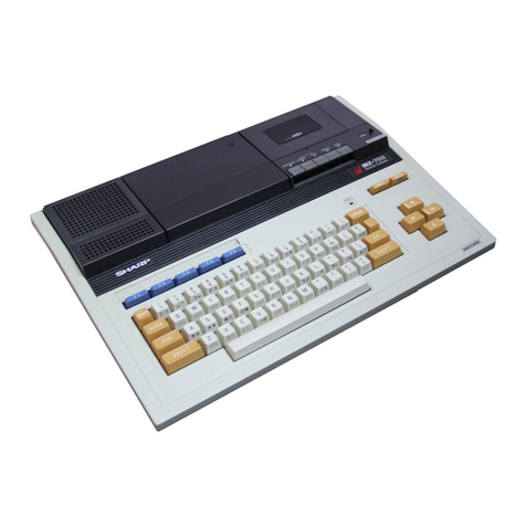
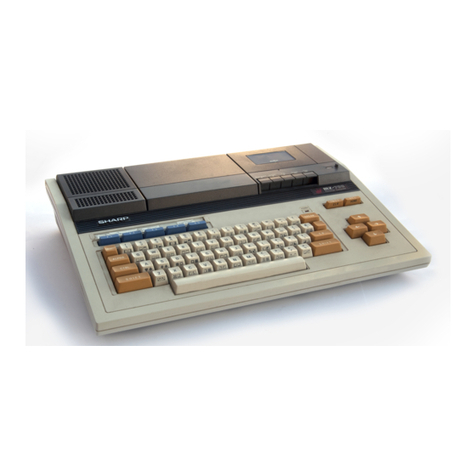
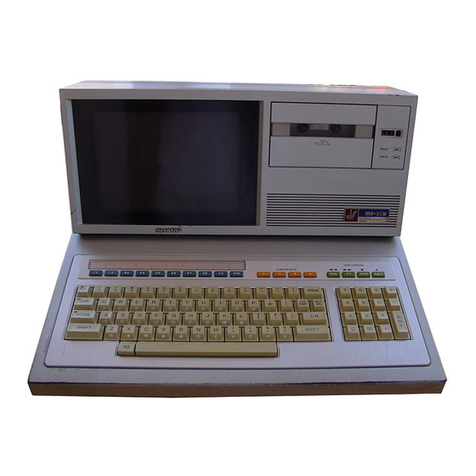
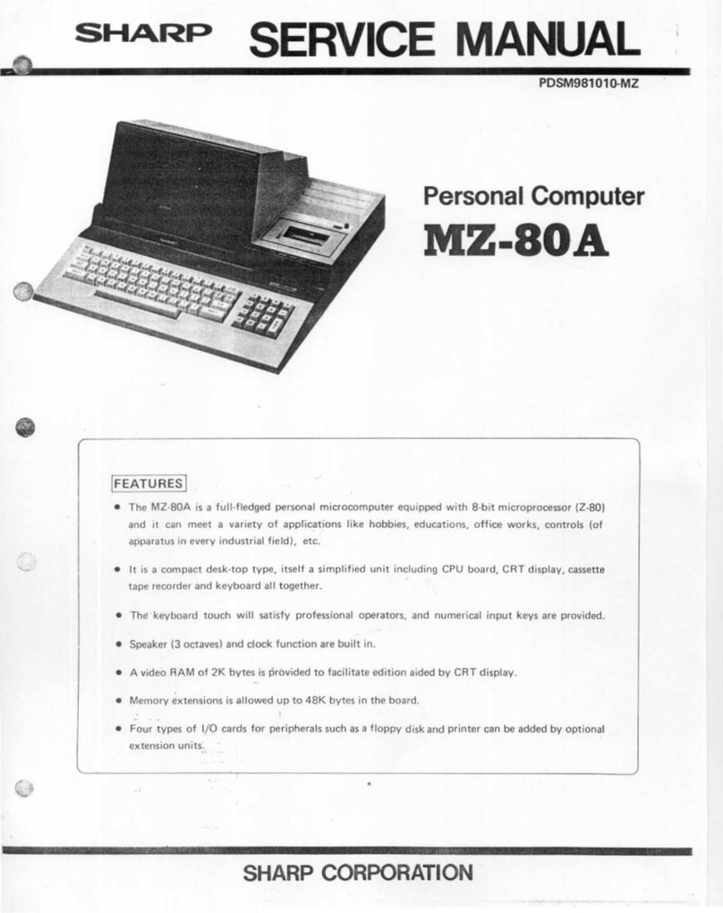
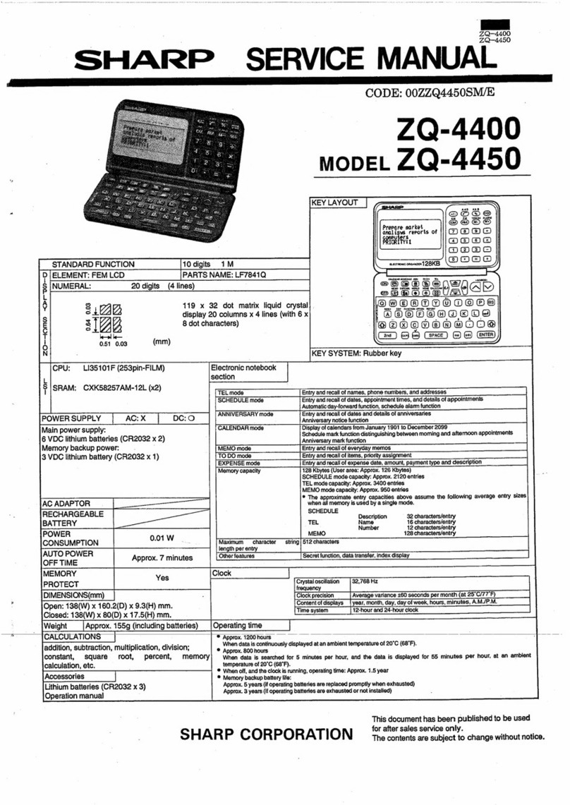
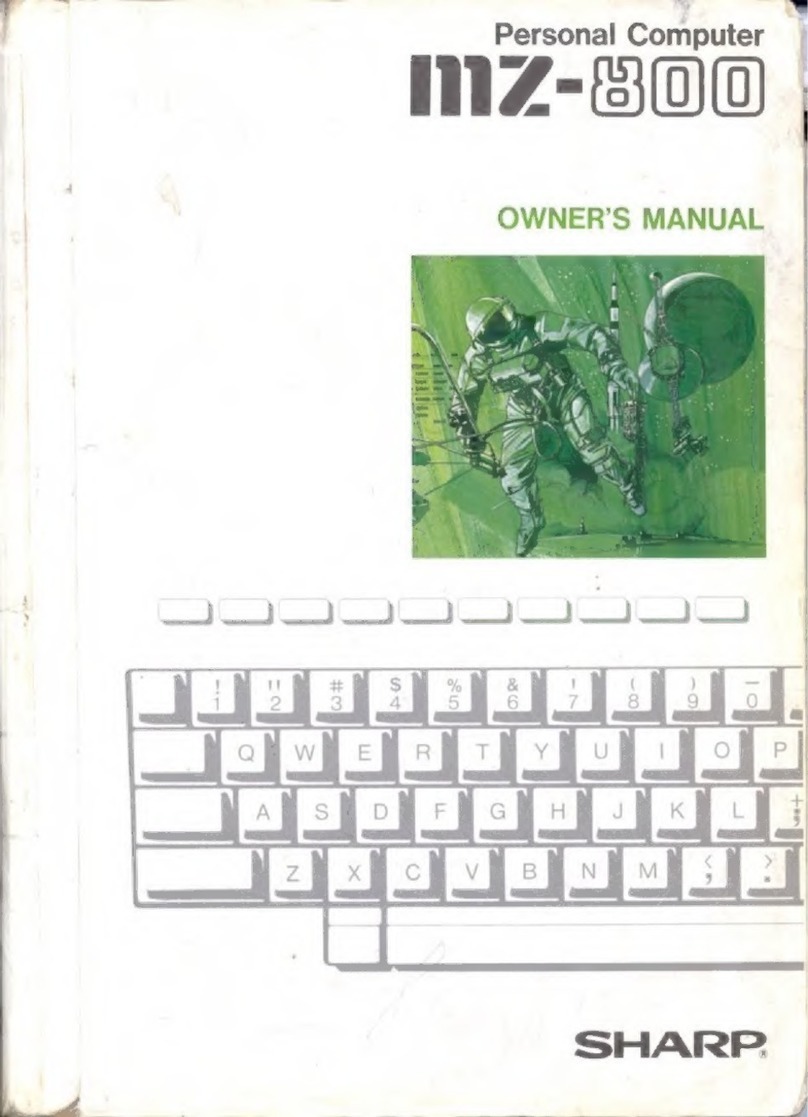
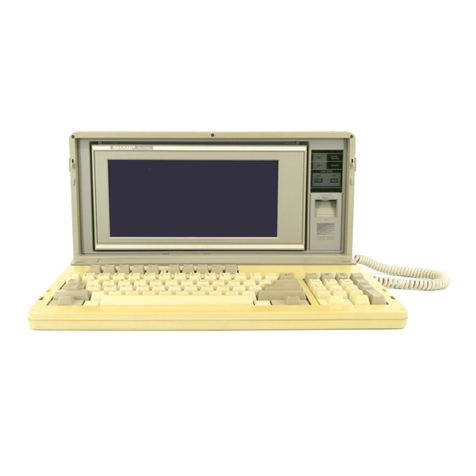
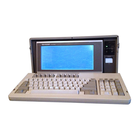
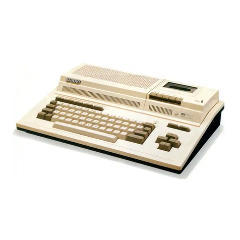
Sharp MZ-80B User manual

SHARP
SERVICE
.MANUAt""
.uu
....................................................
~~~~~M~1
~)
PDSM581008·MZ
•
.~
~
()
[FEATURE~
Personal
Computer
MZ-80B
Options
MZ·80EU
MZ·80I02
(Expansion Port)
(Universal
I/O
Card)
MZ-80GMK (Expansion Graphic RAM)
MZ·80FI (Floppy Disk
I/O
Card)
Optional Peripherals I
MZ·80FBK
(Expansion
Floppy
Disk)
MZ·80FB (Floppy Disk)
:J
•
The
MZ-80B. ste'pped
up
version of
the
MZ-80K,
is
a personal
computer
with
many
new
functions,
• Using a Z-80 processor (4MHz Version}
in
the
CPU,
it
is
capable
of
high
speed
data
processing.
•
It
has
a keyboard
touch
that's ideal
for
a professional
operator
and
is
equipped
with
a 10 numerical
keys
and
10
function
keys,
•
The
cassette-recorder,
using
an
electromagnetic
mechanism,
can
be
stopped/started
remotely.
Programs
and
data
can
be
recorded
automatically.
• With
the
optional
expansion
port,
1/0
card
Can
be
set
in
the
body
of
the
MZ-80B
for
peripherals
such as a
floopy
disk,
print~r,
etc.
SHARP
CORPORATION

~-.
r---------Contents---'-----------------....
MZ-BOB
Specifications. , , , , , , , , , . , , , , , , , , , , . , . _
.......
_
...
,
...
- - . .
..
1
System configuration
and
nomenclature
of
MZ-80B. , , , ,
..•.
,
....
, . - . .
..
3
Configuration
of
MZ-80B
_________________________
. . . . . . . . . .
...
5
Trouble shooting guide. _
..•
_
•.
_
.•
__
. _
••
: _
•.•
___ • • . . . . . . . . . . •
..
7
CPU board section
••..••..•.•••
_
•••••
~
•••••••
-;
•••••.••.••..•.
8
Power supply section
......
'.
'
..
.-
••
'
.............
, , , , . , ,
•••••
'
••
0.'
0'
16
Monitor
TV
section,
. , ,
...
', ,
..
,o.<:":-;"~".
,
~"':',
.
.-,
,
,",
';"~
-~'
.:::~:~~~::",,:,"~,
~<
.
c~·
20
Cassette
tape
recorder
section.
, ,
~
.•...
:;-
..
, . , "
........
'-~".
,
...
, , "
-,
Printed wiring board
and
circuit diagram
.•...•.
0"
••••••••••••
,
•••••
Disassembled view
.....•.......•...............
, . ,
..
, , , , ,
.•.
Packing method
••..
:'
•••••....••••..••.••.•.
:
••..••••.....•
OPTIONS
and
OPTIONAL
PERIPHERALS
Expansion
port
MZ-BOEU
..............
,
.....................
.
Universal
I/O
card
MZ-80102
..................................
.
Expansion graphic RAM MZ-80GMK
............................
.
Floppy disk
I/O
card
MZ-80Fl.
................................
.
Floppy disk
MZ·80F8,
Expansion floppy disk
MZ·80FBK
..............
.
Replacement
parts
list,
..
'
...
,
...
,
......
, - . ' ,
....
,
..........
.
Caution
in Service
'"
Maintain
the
safety
[]nd
protecting
ability
of
the
apparatus
after
service,
..
High voltage shall
not
be rised
to
excess specified level
so
as
to
prevent
This
apparatus
from
the
extra
X·ray
radiation.
24
29
45
51
52
55
58
61
67
70
•
•
•
•
•

•
•
•
•
•
• MZ-80B General
CPU
LH0080A (Z 80A-CPU) Key
Layout
Keys
92
Clock 4MHz ASCII Standard,
10
Numerical keys,
Memory
ROM
2K bytes Function keys, Cursor control keys,
Cassette
tape
deck control keys
RAM
64K bytes (dynamic RAM) Clock
function
Built-in
Editor function Cursor control; up,
down,
right, left,
Display
9"
CRT (green display)
home,
clear.
8 x 8
dot
matrix Edit key
1) Characters;
1000
Delete key
~-,--.-
--._--
----
(40
characters x
25
lines) Power supply
AC
240V
(50Hz)
2) Characters;
2000
Temperature Operating temp;
0°
to
35°C
(80 characters x 25 lines) Storage temp; _15°
to
60°C
----
1), 2): software change-over Humidity
Lower
than 80%
Cassette Standard audio cassette tape Weight Approx_ 16kg
Data transfer speed;
1800
bits/sec. .
---
_.-
Dimensions Width
45cm
Data transfer system; SHARP
PWM
Depth 52cm
Manual or Automatic control Height 27cm
Sound output 400mW max. (440Hz) _
..
--
•
CPU
Board
Section
CPU
LH0080A(Z80A-CPU) 1 pc.
Programmable
l
--
.- .
--
counter
8253
1 pc.
PlO LH0081 A (Z80A-PIO) 1 pc.
. Programmable
ROM
IPL 1 pc.
12K
bytes) !
Character generator 1 pc,
(2K
bytes) peripheral
8255
1
pc_
I
1--. interface i
RAM
Standard; 16K
RAM
32
pcs_
---
---
I
(64K bytes) Other IC's
40
pcs. I
Video RAM; 1 pc. (2K bytes) I
• Power Supply Section • Graphic RAM
(I)
PWB
Section
------
-
Input
AC
240V (50Hz)
~-----
Output
5V
RAM
Static
RAM;
4 pes.
18K
bytes)
----
---t------------
._J
Other IC's 17 pes.
.J
-5V
12V (stabilizing)
12V (non-stabilizing)
-
----
NOTE
Specifications
and
appearance
are
subject to
change
without
prior notice for improvement. In
such
a case, the
explanation
here may
be
a little
different
from the
product
.
-1-
-·
• Display Section
l.
General
specifications
11.
Electrical specifications
Size
9"
Video
output
40Vp-p
standard (35Vp-p
limit)
Vertical 60Hz (vertical),
lS.75kHz
(horizontal)
Resolution
Horizontal
*The
pattern
of
the
left
in
Horizontal •
the
center
of
the
picture
Frequency
must
be clear. •
P~wer
source DC
12V,
1.1
A
±1O%
Non-linearity
Horizontal;
±8% (±14% max.)
distortion
Vertical;
±8% (±12% max.)
Picture
tube
E2728B31;
9"
90°
deflection
Geometrical
Pincushion
dist.;
1%
{2%
max.}
explosion proof type
distortion
Barrel
disl.;
1% (2% max.)
Heater;
12V,
7SmA
Trapezoidal
dist.;
1%
(2% rr,3x.)
1----.
Parallelogram
dist.;'o
(2.5°
max.)
.'
IC's 2
pes.
High
voltil<;Je
Zero beam;
11.0kV
-I (1O.0kV,
min.,
Transistors 7
pes.
I
12.0kV,
max.)
----
Diodes 13
pes.
Power
su
pply
I
DC12.0V,
1.05A
(1.2A
max.)
-
Working
range
12V ±10% •
Sound
output
400mW
max. (440 Hz) Scan size
Horizontal;
10% (15% max.)
Speaker
Bern,
round
dynamiC
type
I
Vertical;
10% (15%
max.)
(32I2l
Horizontal
~-
Control
knobs
Volume, V-Hold, lock"in range I
±300
Hz
(±100Hzlimit)
Contrast,
H-Hold, Vertical [
Brightness,
Focus
lock-in
range
I
-12
Hz
(-6
Hzlimit)
~-
--
Working
440
Hz (OdB)
-10'e
to
SO°C
Audio
frequency
I
-10dB
±4dB
at
100 Hz
temperature
Characte~istic
I
-12dB
±4dB at
10kHz
-•
I
Sound
maxi- I 400mW at
440
Hz
mum
output
'-
~
-----
--
• Cassette Tape Recorder Section
--
System
PWM
recording
BiaSing DC system
5V
±
5%
Erasing
DC
system
Power
source
12V
±
5%
(stabilizing) •
9.5V'"V16.5V (Non-stabilizing) Playback 667
J1sec.
to
333
J1sec.
~-
sensitivity (standard)
Semi-
22
transistors Working
I
_10
oe
to
+40°C
conductors
13
IC,
temperature
~~
9 diodes
--
Storage
-2SoC
to
+65°e
Tape
From
C30
to
e60
,
temperature
,
---
Tape speed
4.75
cm/sec.
~-
-
Track
2-track
monaural
type
~ -
Motor
Electronic
governor
motor
(12V}
L-_~
•
I
-2-

•
•
•
•
•
The MZ·80B system and expansion
thereof
are shown
in
the
block diagram
0.1
Fig.
1.
The inside of
the
dotted
lines
is
the
constitution
of
the
MZ-808,
in
which units enclosed
in
thick-line frames are optional ones.
In
the
expansion
port,
interface cards can
be
inserted up
to
six pieces. The devices outside
the
dotted
lines are optional peripheral
devices and user's devices.
Figures 2 and 3 show the
front
view and rear view of the MZ-80B, identifying
the
parts with names.
r---------------------i
I MZ-80B
I
I
I
I
I
I
I
I
I
I
I
I
I
I
I
I
I
I
I
I
I
I
I
I
I
L
I
CRT
I
Display I
~
f I
Graphic
RAM
CG
Rom
(RAM
11
8KBI
I
'v---
(MZ-80GMKI
32KB
2KB
I I
I
Graphic
Universal
c!-
RAM
18KB
Interface
PTR,
PTP,
etc.
RAM
IMZ-SOI021 I
32KB
V-RAM
+
Character
MODEM
2KS
~
RS-232C Teletvpewriter
Boot
Rom
~
I
etc.
2KB
IEEE-4SS
1.-
IEEE-488
Standard
~~
-"
"W
Interface
I devices
CPU
°0
I
System
Bus
0.
00
ZSOA
f-'
xN
w~
Printer
t
Printer
Interface
IMZ-SOP5')
FD
Interface
1
Floppy
f- (MZ-SOFIJ Disk
I
(MZ-SOFB/FBKI
Key Board I
HD
I I I
;<-
Interface
Hard
Disk
Sound
Ir-
Cassette r
f-
MCR
l~
Mark Card
Interface
Reader
Timer
1.1-
Calor
Color
Display
Intelligent
Interface
I
Terminal
I I
I
Color
Display
---------
______________
---l
Fig_
1 MZ-80B System and Expansion o
Options
D
Future
Development
-3-

Nonglare
~
_________
+
Screen
Special
function
_____
_
Keys
Main
Key
Board
______
--:
Brightness
_______
,
Control
Sound
Volume
Control
Power
recePtacle---""
Power
Switch
---------i..----
Ground-----------J
r---------------------------------
9"
CRT
Display
r------------
Cassette
Tape
Compartment
!~~~J,~~~?i~i~~
..
-,
Cassette
tape
Counter
~0ii!C=1-.
Fig. 2
Front
View
of
MZ·80B
Fig. 3
Rear
View
of
MZ·80B
Cassette deck
~---
Control
Keys
Cursor
Control
Keys
IPL reset
switch
~---"o<,e'
Switch
I/O
Module
Access
Window
No.
1-6

• •
• •
• •
•I
I •
• •
The system diagram
of
the MZ-80B
is
shown
in
Fig.
4.
With the CPU and its
bus
lines
in
the center, the
memorie~
(main memory,
boot
ROM, V-RAMI, keyboard, cassette recorder, CRT display, clock, reset circuit, and I/O
port
are
arranged, showing the relations with PlO,
8225,
8253,
to
constitute
the
MZ-80B.
RESET
SWITCH
'IPL
RESET
SWITCH
FRAME
GROUND
-11-
AC
I
nPOWER SWITCH
~
1 1
POWER UNIT
POWER
TC!ITv
ONIPL
-5V
RESET GROUND
C R
E
L-.
S
0 E
T
A
Z80A
CPU
"
4>
CRYSTAL
16
£ 4MHz
OSCILLA-
MHZ'l
TOR
31.25kHz
Jl
L
E
D
'IPL
RESET ".." Initial Program Loader RESET
-5-
Main Memol)'
RAM
32k
bytes
IPL
ROM 2k bytes
".
RAM
32k
bytes
ADDRESS
SELECTOR
"r I
-,
I1
m
ADDRESS BUS
1
11
1
u:
11
IL
JI
J
~
T
LB
S
r-
HAN
Z80A-PIO
POK
4>
~
I
KEYBOARD
r--
Fig.
4 r

CHARACTER
SPEAKER
GENERATOR AUDIO .n
RoM
2K
bytes
r;::::
AMPLIFIER
11
vLj
-"
V-RAM
l-<--
, CRT
DISPLAY
-CHARACTER
-:v'
2k
bytes
I'r
OSCILLA·
S
TOR
SHIFT
E
f=4
L , REGISTER
E VIDEO GENE·
C
V·RAM
l-
T , RATOR
GRAPHIC I
------I
0
-"
8k bytes
rt
11
T
, I I
11 11
11
J1 -
=
11
11 11
11
V·RAM
=
11
11
11
P GRAPHIC II
.
11 11
, E 8k bytes
ADDRESS
BUS
R (OPTION)
I
=i~
I
II1I
11
, P
H
,....,
E 0
IH
III
v R P
r A T
L I
[)NT
BU
I 0
v / N
~
0
,
!.-
~ ~
P
SHAKE 0
8255 8253 R
.
CO
Cl
C2 T
11
--
]~~
CASSETTE TAPE CASSETTE TAPE
DECK I/O DECK
~-80B
System Diagram
I
No. I
I
No. 6
•

The system comprises four main units.
For quick solution
to
most operational difficulties, follow
the
chart below
to
find which unit
is
causing
the
problem.
Start
Power on
YES
YES
Is
the
CPU
board normal?
YES
YES
End
NO
NO
NO
N9
-7-
Repair
the
power -supply
circuit.
Repi3ir
the
monitor TV.
Repair
the
CPU
board.
Repair the cassette
recorder.
•

The
CPU
b~ard
is
composed of the following six blocks.
When
it malfunctions, first locate which block
is
concerned
with the malfunctions, and next try to check for its corresponding circuits; the wiring diagrams of every block will
be
shown separately.
CPU
inoperative
Display
block
Cassette
recorder
block
Keyboard
block
Audio
block
NO
Clock
block
NO
YES
YES
YES
YES
YES
<e
noperative
YES
immediately
after
>------0-1
power
ON,
NO
Check
RAM
and its
peripheral
circuits
{by
usinfj
RAM
checked,
Check
video
RAM
circuit.
Check IC23
(8255)
and its
peripheral parts,
Check
IC24
(LH0081A)
and
its
peripheral parts.
Check IC23
(8255)
and
its
peripheral
P<lrts.
----'
Check
IC19
(8253)
and its
peripheral parts,
Check
memory
circuit
and
its
peripheral parts,
•
Checki~g
rnetl1ods()f~~h
circuit -,,;
"I,
","
..
,,,'
"_
•
",.
'"
_
:.l.C.By.tbuChinglC package
by
fingers:c .
.•.
Ifthey
seem too
hot
by
heat
gene~atiori;
2.
I(:::--j{ defective" le
'Idad
'is
'hea~'y
'or
~'~mporients
are
~ouc~~-
'"each'
other
(ROM
and V·RAM are
.
ex.~mpted
f;~m
this checking).
e,
If.-
a circuitry state changes to,
an~ther;
Sold~ring
is-
poor, socket contact
is
impro'per or printed-
wiring
is
erroneous.
By
using a synchroscope:
•
If
the
relation between input and
output
of TTL
IC
is
illogical, this means defe.etive
IC
gate.
• Check if the voltage of TTL
IC
is
as
specified: Highle,;el; over 2.4V"Low level; below O
..
5V.
• When the signal'is between the high and low levels,
is
~here
circuit t?uching or
!C
malfunction?
-8-
,
,

• Display Block
DO
-
I Bus driver
07
-
AD
Al
1
0
cso
SOC
VGAT
Whole
rever
H
E
se
~
I Problem
CSOO
No
sync. signal
I
No
video signal
wFi-
\
/
Characters displayed
but
position
abnormal
\
Character generator Vide
-/
Shift
register Sync
/
';".,
o
signal
. signal
'----
-
Video
RAM
L--
lr
Oscillator
V Oisplay
controller
f------
circuit
Address
selector
~
I
Block Diagram around
Video
RAM
....
....
....
, Check Point
.
Is
the correct signal present at pins
12
and
13
of
IC36 ?
Yes:
Check IC36.
No: Check IC42
and
IC43 and around them.
(In particular, check
if
the
input
of
8MHz, 16MHz
and
other
clocks are correct (Wave
form
is
shown
on
page
15.))
Is
pin 16
of
IC42 at a high
level'
No: Check IC23.
Yes:
Proceed
to
the
following.
:
Is
a video
signal
present at
pin
8 of
IC46?
Yes: Check IC31, IC33 and IC36.
No: Check IC42 and IC43 and around them.
(In particular, check if the input of
8MHz
and
16MHz
and
other
clocks are correct (Wave
form
is
shown on
page
15.))
Is
the signal at pins 3,
6,10
and
13
of
IC37, IC38
and
IC39
correct?
Yes:
Check the
address
of
IC41
and
the signals
of
IC37,
38
and
39 connected to
it.
-9-

Position
is
correct
but characters
are
abnormal
Displayed
characters
are
abnormal
• Keyboard Block
D7
I
DO
MI
Al
AD
-\
-----/
B7
I
BD
LHO
A4
081A
A3
I
PlO
AD
~
I
INT
lED
Does
not
accept key entry.
No: Check IC 37, 38, 39,
42
and
43.
Check the common line
of
IC22, IC41
and
IC44
and
around the IC22.
Check
A,
-
Ao
and
D,
-
Do
of
1C45
and
IC42.
Key strobe Key board
cancelling.signal
Decoder
Block Diagram around Keyborad
,Point
Is
key strobe present?
Yes:
Check keyboard, IC24
and
around it.
No: Check IC25, IC27, IC28. IC29
and
IC36.
-10
-
If
they are normal, check
IC24
and
around it.

A3
A2
Al
AO
Peripheral
86
interface
85
18255) B4
C7
C6
C5
C4
1--
-,
b STOP
I
b
I
p
p
I
PNL
BLKl
8LK2
P
RDATA
P
TREADY
b
WREADY
I
I
P
WDATA
P
WRITE
bREW
I
o
OPEN
I
L
_____
J
Block
Diagram around
the
Cassette
Condition
~
.
--T:-Ch~Ck
Point
,I,:
Load
is
not
possible.
Is
there
a signal
from
pin
6
of
le
26?
YES.
Check IC23.
NO.
Check
IC26.
Save
is
not
possible.
Is
there
a signal
from
pin
10
of
IC23?
YES.
Check
IC26.
NO:
Check
IC23.
Motor
does
not
turn.
Check
IC23.
MOtor
does
nOt
stop.
Check
IC23.
-
11
-
For cassette

• Clock!Audio Block
07
I
DO
,
-I
IRO Programmable
counter
18253)
CS
GO
Al
Gl
AD
-cc
',,'
"
-~;
troblem,.
.,;,
•..
Clock
tunction
is
abnormal.
Audio
output
is
abnormal.
~
31.25kHz
07
I
DO
IRO
IWR
CS
Peripheral
interface
182551PC2
Counter
#0,
#1,
eset signal
,
Al
AD
RESET
Block Diagram around
Clock!
Audio
Block
.'
.'
....
' " Check Point
-
Is
there a 31.25kHz
signal
present
at
pin
9 of
IC19 ?
Yes:
Check IC19 (8253)
and
around
it.
No: Check IC42
and
around it.
Is
an
output
signal
present at pin 4
of
IC31?
Audio
output
.>~;
Yes: Check amplifier section
in
the display board.
No: Check IC23, IC31
-12
-

• Memory/Reset Circuit Block
AO
-
A13
Data selector
RAM
block
Problem
Picture
"panic"
when
power
is
on.
Abnormal action
immediately after end
of
program due to
BOOT
program
Error
when program
is
in
RAM
AO--
A10
ROM block
Memory/Reset Circuit
Memory control
circuit
07
DO
,Check Point
CPU
control
bus
A15
1
Al2
Does
pin 26
of
I
C3
go
from
High
to
Low
when the BOOT
reset
SW
is
pushed?
No: Check IC33
Yes: Proceed the following.
Is
pin 15
of
IC2
High?
No: Check IC34
Yes:
Check address line
AO
-
A15
(ICB, IC10)
Data line
DO
-
07
(ICll)
Control line (lC7)
IC2, ICS, IC14, IC1B
Is
pin 15
of
IC2 at
Low
Level?
Yes: Check IC34
No: Check IC2
Check RAM
-13
-

.. How
to
Use
RAM CHECKER
Insert
RAM
CHECKER into BOOT
ROM
socket and turn
the
power on. Then
RAM
TEST·1 and
RAM
TEST-2 will automatically
be
carried
out
from
RAM
address
$0000
to
address $F FFF
as
shown below
and.the tested results will
be
displayed.
The checker tests
the
store by dividing
it
into two parts of addresses $0000
to
$7FFF
and
$8000
to
$FFFF.
Example
of
the
test results (When all RAM'. are normal)
Check
RAM
(l)
block, 16K bytes,
RAM
(ll) block 16K bytes
1)
RAM
TEST·1
A writelread test of data $00 and
$FF
is
carried
out
from address
$0000
to
$FFFF,
and
if
an error
occurS ERROR
is
displayed
in
the
16K bytes unit.
Example
of
above mentioned display
IOOOOi'::
O.
K. I
....
· Result of writehead test from address
$0000
to
$3FFF
is
normal.
,_J
_:.
'~11'
Example of display when ERROR appearS.
IER:23,5B:00,
01
1...........
Write
in
data was
$00
at
address
$2358
but
read·out data
was
$01.
An
error
is
displayed by
the
address
number
at
which
the
error takes place, and
the
excution
of
check
is
stopped
at
the
address.
2)
RAM
TEST·2
Write/read
test
is
carried
out
with
the
following items_
al
Write-in data $00 (From address $0000
to
$7FFF)
b)
Write-in data
$FF
(From address $0000
to
$7FFF)
c)
Write·
in
data
$00
(From address
$7FFF
to
$0000)
d)
Write-in data
$FF
(From address
$7FFF
to
$0000)
e)
Write-in data
$FO
and
$OF
entered alternately (From address $0000
to
$7FFF
and vice verSa.)
f)
Write·in data
$00
(From address
$8000
to
$FFFF)
g)
Write-in data
$FF
(From address
$8000
to
$FFFF)
hi Write-in data
$00
(From address
$FFFF
to
$8000)
i)
Write-in data
$FF
(From address
$FFFF
to
$8000)
j) Write-in data
$FO
and
$OF
alternately (From address
$8000
to
$FFFF
and
vice
versa)
Example
of
ERROR in
RAM
TEST·2
, .RAM TEST-2
00
FF
00
ER·23FF·01
Test results of
a)
and
b)
were normal
but
in
c), although data
$00
was
written in address $23FF, read-out
data
was
$01. When ERROR
is
displayed
in
the above mentioned
RAM
TESTs, decide which
RAM
block
is
bad according
to
the
memory
address where
the
error occurs. Then
you
can decide which
RAM
is
bad in the
RAM
block where
the
error occurs by
the
bytes
pattern
of
the
write-in data and reao-out data.
In
the
above
example, you can tell
that
it's
RAM
(I) block by
$23FF
and
that
RAM
1
is
bad because write-in data
is
$00
but
read-out
data
is
$01.
(See
Fig.
next)
t~'
06 05
04
03 02
01
DO
-------
Write·in date
$00
0 0 0 0 0 0
~Error
Read-out data
$01
0 0 0 0 0 0
:,:
':
l:
:
..
i
to
occur
-14-

RAM
III
RAM
121
RAMlml
RAM
IIYI
D7
~'SHARP81
P
16[
PSHAR
24[
P
321
D6
P
71
P
151
P
231
P 311
D5
P 61 P
14/
P
22[
P 30[
D4
P
51
P
131
P
211
P
291
D3
P
4[
P
121
P 201 p 281
D2
P
3[
P
11[
P 19 1 P
271
D1
P 21 P
101
P 18 1 P 261
DO
~
1 I P
91
P 171 P 251
•
Waveforms
of
CPU
Board
Pin
23 of IC42
Pin
22 of IC43
Pin
20
of IC42
Pin
20
of IC43
-
--
lSMHz
8MHz
4MHz
Pin
19
of
IC42
Pin
21
of
IC42
Pin
21
of IC43
Pin
19
of IC43
------
~
-
'-----
2MHz lMHz lMHz
Pin
10
o~
IC42
F'in
12 of IC36 Pin 7 of IC42
J U I
-
,---
16.64ms
64", 64",
Pin 9 of IC19
3L251(Hz
-
15-

~
AC
240V
50Hz
~
•
Filter circuit
r--
Voltage
stab;';,er
c;rcu;t
:
Transformer L Rectifier
circuit 1
I-- I--
f-
Voltage
stabilizer circuit
Rectifier
circuit
\
Voltage stabiliz.er circuit
Rectifier
circuit 1
Block Diagram of Power Supply Circuit
•
..
•
----.--. --------'_._ •
_____
•
______
.0
____
-
__
..___________
+12V
r-
+12V
E
+5
~
-CO
-5V
+12V
+5V
'-
E
..

•
•
•
•
•
• Trouble Shooting Chart
Problem (1)
No
voltage
at
any
output
terminal.
Check primary circuit which includes
the
transformer.
Problem
12)
Problem (3)
No.
-5V.
Is
approx.
11
V
present
on
both
ends
of
C201?
Check
IC201,
C203
aod R201,
No
+12V.
NO
NO
Chlt~k
t101,
F201,
D201,
C201 and
C202.
Check
primary
circuit
which includes
T101.
Is
voltage
at
the
NO
other
output
~~~------------------------------------------------
__
___
terminals
normal?
Is
approx. 24V
When
A309
is
open,
does
a
O.2Vpp
appear
at
pin
12of1C301,
Check
0301,
Q302
and
smoothing
circuit,
NO
NO
Check
IC3Ql
and
circuit
of
IC301.
-17
-
Check
F301,
nOl,
D301.
C309. C301,
C302
and
C304.
Check
primary
circuit
which
includes
Tl01.

Problem (4) No
+5V,
Is
voltage at the
other output
terminals normal?
IS8pprox.14V
present at pin
15
of
IC4017
NO
NO
When
R405
is
NO
open, does O.2Vpp
appear'>='---
____
~
at
pin 12
of
IC401?
Check
Q401,
0402
and smoothing
circuit
Problem (5)
-5V
is
abnormally high.
Check IC201
Problem (6)
+12V
is
abnormally high.
Check 1C401 and
circuit
of
IC401
Check
0301,
0302
and IC 301.
Problem (7)
+5V
is
abnormally high.
Check
0401,
0402
and IC401.
Check F401, T101,
D401,C412,C401
-C404, C407
Check
primary
circuit which includes
T101.
Other manuals for MZ-80B
4
Other Sharp Desktop manuals

Sharp
Sharp MZ-80B User manual

Sharp
Sharp MZ-3500 User manual

Sharp
Sharp PC7000A User manual

Sharp
Sharp MZ-800 User manual

Sharp
Sharp PN-L602B User manual

Sharp
Sharp CE-159 User manual

Sharp
Sharp MZ-3500 Instruction manual

Sharp
Sharp ZQ-4450M User manual

Sharp
Sharp YO-270 User manual

Sharp
Sharp YO-250M User manual

Sharp
Sharp PN-TPCi7W7 User manual

Sharp
Sharp MZ-700 Series User manual

Sharp
Sharp PC-4741 User manual

Sharp
Sharp Shuttle PN-SPCi5W7 User manual

Sharp
Sharp MZ-700 Series Installation guide

Sharp
Sharp MZ-700 Series User manual

Sharp
Sharp PC-7200 User manual

Sharp
Sharp ZQ-3000 User manual

Sharp
Sharp PC-4741 User manual

Sharp
Sharp MZ-350C User manual