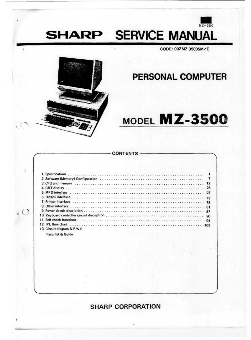
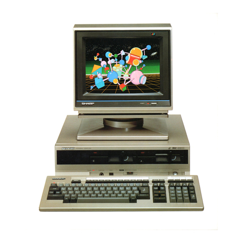
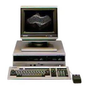
Sharp MZ-3500 User manual

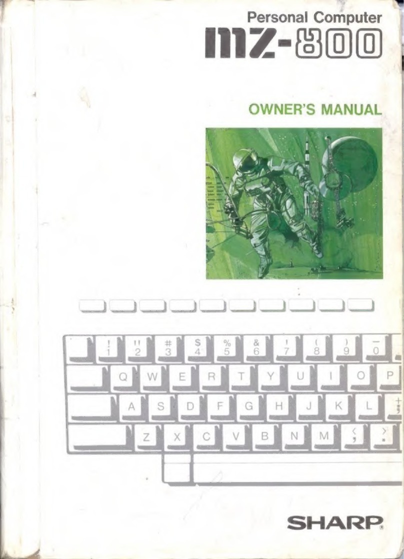
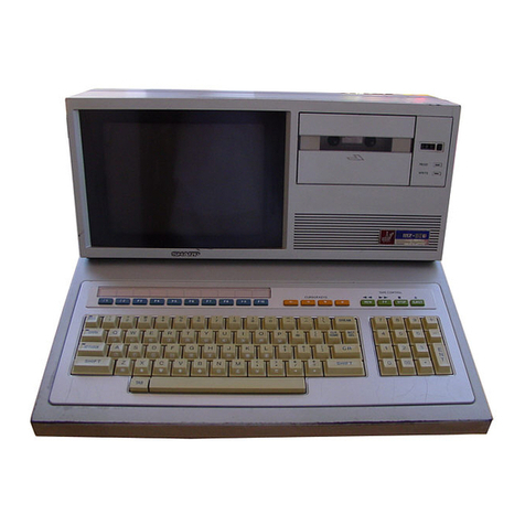
MZ-3500
SERVICE
MANUAL
CODE:
OOZMZ
3500SM/E
PERSONALCOMPUTER
MODEL
Z-350
CONTENTS
1.
Specifications
1
2.
Software(Memory)Configuration
7
3.CPUand
memory
12
4.CRT
display
25
5.MFD
interface
52
6.
R232Cinterface
72
7.
Printerinterface
yg
8.
Otherinterface
81
9.
Power
circuit
description
gy
10.
Keyboardcontroller
circuit
discription
90
11.
Selfcheckfunctions
94
12.IPL
flow
chart
103
13.
Circuitdiagram
&
P.W.B
Parts
list
&
Guide
SHARP
CORPORATION

M
7
3500
1.
SPECIFICATIONS
1-1.
Specification
ofthe
main
unit(Model
35XX)
Outline
1)
High
speed
processing
usingmulti-CPL'
2)
Built
in
mini
floppydisk
3)
Built
in
printerinterface
and
RS232C
Aerial
interface
4)
Connection
ofuptotwo
videodispla,
mitt
(separate
graphic
display
or
overlaiddisplay
possible
ontwo
individual
color
monitor
units)
5)
Permits
theuseof
standardCP/M
Model3530
incluse
a
single
double-side,double
density
mini
floppy
disk
and64KB
RAM.
ModelMZ3540
hastwo
double-side,
density
mini
floppy
disks
and
64KB
RAM.
LSI
DISPLAY
MFD
Other
I/F
Other
functions
Software
Accessories
CPU
MEMORY
I/O
MZ353X
MZ354X
Light
pen
Keyboard
Printer
RS232C
Multi-CPU
processing
ROM
RAM
Custom
LSI
GDC
FDC
PIO
SIO
TIMER
CLOCK
Screen
structure
Elements
Attribute
Colors
I/F
One
double-side,
double
density
floppy
disk
Two
double-side,
double
density
floppy
disks
IPL
C,G
For
main
CPU
For
sub-CPU
Shared
RAM
VIDEO
RAM
Memorymapper
Screen
controller
CRT
controller
Floppydiskcontroller
Parallel
I/O
port
Serial
I/O
port
Counter
Clock
Model
3531includes
a
single
double
side,
double
density
mini
floppy
disk
and128KB
Model3541
hastwo
double
side,
double
density
mini
floppy
disks,
and128KB
Z80A
microprocessor
x 2
8K
Byte
ROM
8K
Byte
ROM
64KBit
DRAM
x 16
chips
or8
chips
16KBit
SRAM
x 4
chips
16KBit
SRAM
x 1
chip
16KB't
SRAM
x 1
chip
4KBit
SRAM
x 2
chips
TH
SP6102R001
CSP-1
SP6102C002
CSP
2
SP6102C003
MPD7220
pPD765
8255
8251
8253
/iPD1990AC
80
characters
x 25
lines.
80x 20,40x 25.or40x 20
8x
16,8x8
Reverse,
blink,
line
(horizontal,vertical)
8
colors
on
eachcharacter
and
backgroundcolor
2
channels(applicable
CRT640x
400,
640x
200,
B/Wor
color)
256
bytes/sector,
16
sectors/track,
80
tracks/disk
Built-in
interface
for
optional
MFD
Dedicatedkeyboard
Centronicsinterface
No
protocol,
asynchronus
mode,
110to
9600
bps,half-duplex
Speaker
(500mW)BatterybackupclockHALT
SW
Speaker
volumecontrol
FDOS
CP/M
BASIC
Utilities
Basic
CP/M
ExpandedCP/M
High
class
compatible
with
PC3200BASIC,supplemented
and
graphic
controlcommands
Expanded
RS232C,GPIB,
and
GPIO
BACKUP,
INIT,
COPY,DEBUG,
KILLALL
Intstruction
Manual
master
floppy
disk
power
cord

MZ3500
1-2.MZ-1K01(Keyboard)
specification
Outline
Specification
MZ1K02U.S.keyboard
(ASCII)
MZ1K03:U.K.keyboard(ISO).
MZ1K04
German
keyboard
MZ1K05:
Frenchkeyboard
LSI,
1C
Keys
(98)
Interfacing
cables
Other
Cabinet
Keyboard
controller
CMOSIC
Sculpture
key
Alphanumeric
keys
Modeswitch
61
1
80C49
or
8749
4049x2,4514
Mechanicalcontactkey,
with
life
of
10,000,000
operations.
Tenkey
15
Function
keys
6
Definable
keys
10
For
datatransfer
with
theCPU
(serial)
and
power
supply
(transmissionunder
15,000
baud)
Use
of
coiled
cable
with
8-pin
DIN
plug
Repeat
function
Indicators
(4
LED's)
Molded
Size
(Wx H
Automatic
repeatoccurs0.64secondsafter
....
. 2
Two-keyrollover
continuous
depression
ofthe
samekey.
POWER,
Alphanumeric
keys
Color
xU
Officegray
467
x35x 190
Weight
|
About
1
.5kg
(3.3
Ib)
Keyboard
layout
Refer
tothe
page
TIN
"CIRCUIT
DIAGRAM"
1-3.MZ-1U02
Outline
Specifications
Expansion
unit
forthe
MZ-3500
series
CPU,which
canbe
attached
tothe
rearside
ofthe
main
unit.
Optional
boards
are
plugged
intothe
expansion
box.
The
expansion
box
will
accomodate
upto
four
option
boards.
Number
of
slots:
4
slots
Slot
connector.
60-pin
edge
connector
x 4
Area
ofthe
slot
inserting
option
board:
140.5
x 140
Slot
for
option
and
slot
number
MZ-1R06
(expansionRAM)
SFDI/F
ExpansionRS232C
GPIO
GPIB
(IEEE
I/F)
Slot
1
o
o
o
o
Slot2
o
o
o
0
Slot
3
O
O
o
o
Slot
4
O
0
o
o
-2-

MZ3500
Expansion
unit
Screw
(1)
1-4.MZ-IR03
Outline
Specifications
Optionalboard
used
graphicdisplay
functions
with
the
Model-3500
series
CPU.
It
includes32KB
of
RAM.
Itis
inserted
through
the
slot
onthe
front
panel
ofthePU.
The
MZ-1U02
expansion
boxisnot
required.
LSI
Graphic
functions
(Color
must
be
specified
for
each
dot.when
the
color
video
unit
isin
use)
Software
GDC
Graphic
controller
Basic
(buit-in)
vinrn
HAM
Expansion
(optional)
~~~~~
—
____WDEO
RAM
640x 200
green
monitor
640x 200
color
monitor
640
x 400
green
monitor
640x 400
color
monitor
BASIC
graphic
control
statements
MPD7220
16KDRAM
x 16
(32KB)
16KORAM
x 32
(64KB)
32KB
(basic)
640x 200
dots
Two
screens
_____
640x 400
dots
One
screen
^______-
— ~"
SDISP
ODISP
CHANGEDISP
GCOLOR
CLS
PSET
PRESET
LINE
GTABLE
CIRCLE
PAINT
GINPUT
GDISP
GPRINT
GREAD
CENTER
GCURSOR
GSCROL
SYMBOL
SCALE
96KB
(maximum
expansion)
640x 200
dots
Six
screens
640x 200
dots
Two
screens
640x 400
dots
Three
screens
640x 400
dots
One
screen
Screen
designation
fortwo
videounits.
Designation
of
output
screen.
Modedesignation
Graphic
pattern
designation
Cleared
bythe
colorspecified.
Dotset
Dot
reset
Line
creation
Tablecreation
Circlecreation
Paintover
Input
of
graphicpattern
Display
of
graphicpattern
Output
of
graphicpattern
on
printer
Read
of
coordinates
Input
of
pattern
within
the
specified
area
Graphic
cursorposition
designation
Graphic
screen
scrolling
Graphic
symboldisplaying
Scren
scle-down
designation
-3-

MZ3500
1-6.
MZ-1R06
Outline
Specifications
Optionalboard
for
memoryexpantion
ofthe
MZ-3500
sries
CPU.withthisoption
the
mainmemory(RAM)
canbe
expanded
uptoa
maximum
of256KB.
This
option
plug
into
the
expantion
boxin
slot
1or3.
LSI
Memory
and
user
area
Basic
Expansion
64KDRAM
x8
(64KBI
64KDRAM
x8
(128KB)
Totalcapacity
of
the
main
CPURAM
BASIC
(RAM
BASE
SYSTEM
:
AREA
USER
'
AREA
Main
CPU
only
128KB
•57KB
80KB
Use
of
MZ-1R06
192KB
«-
128KB
Using
eight
64K
RAM's
on
theMZ-1R06
256KB
*-
208KB
-
4
-

MZ3500
1-7.
MZ-1D07
Outline
Specifications
High
resolution
MZ
3500
series
12
green
Video
tube
Display
capacity
Display
size
Input
signals
Power
supply
Cabinet
Adjustingknobs
Accessories
Type
monitor
Non
glare
green
Size
12",
90"
deflection
Fluorescent
color
P39
(green,
long
PERSISTANCE)
Total
number
of
display
characters
2,000
characters
(80
characters
x 25
lines)Displaycapacity
640
horizontal
dots,
400
verticallines
220x 145
Method
Horizontal
Separate
input,
TTL
level
20
86kHz
29W
powerconsumpt
MoldedColor
Size
(Wx H x U
3
Vertical
47
8 Hz
ion
Office
gray
324x310x356
Weight
7.2kg
Verticalsynchronization,
contrast,
brightness
CPU
connection
cable
and
power
cord
and
Tilt
stand
r
-5-

MZ3500
1-8.
System
configuration
of
Model3500
Keyboard
MZ-1K02
MZ-1K03
MZ-1K04
MZ-1K05
Printer
'
IO2824E
I
II
Option
MFDI
I
CE-331M
|
II
"Model-3541
=
Model-3531
+
MZ-1F03
6

MZ3500
2.
SOFTWARE(MEMORY)CONFIGURATION
Memory
will
be
operatedunder
four
states
of
SDO
~
SD3,
depending
onthe
hardware
and
softwareconfigurations.
Inthe
paragraphs
to
follow,
description
will
be
made
for
those
four
states.
2-1.
SDO
(INITIALIZE
STATE)
SDO
can
only
exist
immediatelyafterpower
on,andthe
system
executes
IPL
underthis
condition
and
that
the
system
thusloaded
will
automatically
assign
memory
area
for
SD1,SD2.
and
SD3.
MAIN
CPU
SUB
CPU
MAS
MA2
MAI
MAO
FFFF
0
0
0
0
cooo
BFFF
8000
7FFF
RAMA
RAMA
RAMA
4000
3FFF
i
|
ROME
[
I
I
2000
I '
0
0
0
1
V
FFFF
RAMA
1
1
1
1
T
MS1
=° (D
MSO
= 0 (L)
?
IRAM(COM^
jOO1——
^\
reoo1
\\
u
\\
\\
\\
N
v
V\
\
ROM
(SPAPE)
OFFF
0000
ROM
JPL
RAM
(COM)
ROM
IPL
4000
27FF
2000
1
FFF
0000
*7

M7.
3500
Operational
description
(1)
Upon
reset
after
power
on,the
main
CPU
loads
the
contents
ofthe
initial
program
loader
(IPL)
into
RAM
starting
at
address
4000H,
duringwhichtime
reset
is
applied
tothe
sub-CPU.
TIMING
OF
RESET
SIGNAL
Vtc-
SYSKES-
SKES-
pr)WFjJSUB
CPU
PO*E^
START
POWER
OFF
(2)
The
main
CPU
then
terminates
resetting
thesubCPU
and
starts
the
sub-CPU.
Atthe
same
time,
theROM
IPLis
assigned
tothe
sub-CPU.
(3)
The
main
CPU
then
send
the
memory
allocation
(state)
to
SD1,
and
starts
to
load
DOS
from
the
system
floppy
disk.
Signal
generated
from
the
CR
network
and
powersupply
Output
signal
from
the
main
CPU
port
MAIN
CPU
START
a.
Main
CPU
reset
time
b.
Main
CPUIPL
loadtime
Memory
Map
Data:
1.
ROM-B
is
tested
to
determine
if
ROM's
are
present.
2.The
ROM-IPLfunctionsunder
control
ofthe
main
CPU
at
first,
but
later
it
functionsunder
the
sub-CPUafter
theIPL
program
has
been
loaded
in
RAM.
3.
RAM-COM
is
shared
by
both
the
main
CPUandthe
sub-
CPU.
INITIALIZE
FLOW
«TABT
4.
Memories
other
than
described
above
cannot
be
accessed
under
theSDO
state.
5.
Bank
select,MAO~MA3,
is
used
within
the
address
range
ofCOOOH-FFFFH.

ROM-IPL
1.An8KBROM
(2764
or
mask
ROM
equivalent)
is
used
forthe
ROM-IPL.
2.
When
the
system
reset
signal
turnsfrom
lowto
high
state
after
power
on,the
main
CPU
starts
to
operate
At
this
stage,
the
ROM-IPL
is
addressed.
3.TheCPU
starts
from
address
OOOOIROM
address
10000)
4.The
main
CPU
sets
the
sub-CPU
reset
signalfrom
lowto
high
state
asit
goes
outofits
initial
state
viathe
memory
mapper
andthe
sub-CPU
starts
to
operate.
At
this
point,
the
ROM-IPL
is
addressed
bythe
sub-CPU.
5.
Address
0000
ofthe
sub-CPU
isROM
address
(0000)
The
memory
area
above
ROM
address
(1000)
cannot
be
used
bythe
sub-CPU
because
themamCPU
initial
program
has
beenloaded
there.
2-2.
SD1
(SYSTEM
LOADING
&
CP/M)
SD1
determines
which
operating
system
tsin
use.
The
system
is
loaded
inthe
CP/M
(Control
Program
for
Micro-
processors)
mode.
MZ3500
Mam
CPU
logical
address
(during
IPL
operation)
Logical
address
ofthe
sub-CPU
ROM
physical
address
OfFF
0800
0000
1
FFF
1
800
1
7FF
1
OOP
OFFF
0800
07FF
0000
1
FFF
1
800
I
7FF
1
OOP
OFFF
0800
07FF
0000
ROMIPL
MS1
= 0(L)
MSO=l(Hj
MAIN
CPU
rr
F?'
f.ftf
r
^
n
RAMicnu:
4
3
i
\
\
>
\
x
\
V
\
^\
\\
\
\
\
\
\\
\
\
\\
\
\
\\
\\
\\
RAMsn
RAMSA
KAM«.(IH)2000
1FFF
-9 -

MZ3500
Operational
description
(1)
As
soon
asthe
sub-CPU
is
started,
it
initializes
theI/O
port
and
waits
for
programtransfer(IOCS)
from
the
mainCPU.
This
IOCS
(Input
Output
Control
System)
is
the
programresident
at
address
4000H-5FFFH.
(2)
Asthe
main
CPU
loads
the
information
from
sector
Communication
between
Main
andSUBCPU
"1"of
track
"0"ofthe
floppy
disk,
it
loads
the
IOCS
and
bootstraproutine
tothe
sub-CPU.
(3)
The
bootstrapprogram
is
loadednext.
(4)
The
bootstrapprogramdetermines
rnemory
allocation.
BUSRQ
H
OUTPUT
|
(ISOLATION
OFCOM
RAM)
2:3.
SD2
(ROMbasedBASIC)
SD2is
activewhen
"SHARP
BASIC"
is
executed
via
ROM.
MAIN
CPU
MS]
= I (H)
MSO
= 0 Li
SUBCPU
MAS
00
0000
BANK
MA2° °
00.1
SELECT
MAI0 0
1100
MAO
FFFF
i
Sffi
i
\
IFF?
IFF?
J
0000
(MO2
01
0101
1
III
R\MAKAMB
4
3
2
ROME
ROMA
0
1
1,2,3|4
ROMCROMUROM!
ROM2
0001
MO1
00110
MOO
01010
0
1
I
0
1
11
01 1
1
0 0
I0 0
1
0 1
11
K
\ML
2|3,4
1I 1
00 1
1I 0
01 0
1
11
11
KAMI!
2,
3 |
4
1.
Bank
select,MAO~MA3.
is
effective
for
memory
area
COOOH-FFF
FH.
2.
Bank
select,MOO~MA2,
is
effective
for
memory
area
2000H-3FFFH
-
10
-

MZ3500
2-4.
SD3
(RAMbasedBASIC)
SD3is
active
when"SHARPBASIC"
is
ececuted
via
RAM.
"SHARP
BASIC"
is
loaded
inRAM
from
the
floppy
disk.
RAM
BANK
SELECT
ROM
BANK
SELECT
MAS
MA2
MAI
MAO
Ffft
\
gFFF
1FFF
0000
M02
[NOI
MOO
MSI
= 1<H)
MAIN
CPU
MSO
= HH)SUBCPU
0000
0000III!
1
0000
1111
0000
1
0011001)0011
1
010101010101
1
IIIIIIIII
lRwnuf%
r 1
\\
RAMB
RANC
KAMI)
v\
\v
1
2,3,4
1,2,3,41,2,3,4
\\
\\
N\
-
vx
\\
RAN.
SP
\\
RAN
SC
,\ ,
RAM
SB
KU
"°
RAMA
ROM!
ROM2
KOM3
K(IM4
\\ROMBAS
k
' SUBCPU
]L
ROM
1PI
0000 ) i ]
0
0 1 " 1 0 0 1
010
101 0
1.
Bankselect,MAO-MA3.
is
effective
for
memory
area
COOOH-FFFFH.
2.
Bankselect,MOO-MO2,
is
effective
for
memory
area
2000H-3FFFH.
Operationaldescription
The
state
ofthe
system
is
determined
bythe
bootstrap
program
before
the
load
ofthe
system
program.

3.CPUAND
MEMORY
3-1.
Block
diagram
1)
Relationbetween
MMR
(MainMemoryMapper)
and
main
memory.
,RAM
I
(II'TION
1
4-
RAN
'
64KBV2)
VI
°l
RECEI
VFR
1
1
OPTION
.
Ml
DM1
I
MO*J
OK
IIK U MO*400
klMilI 1 ION
I
JK»2K*
J
(,
{)
R
siv i
(.us
TOM
1
SICSI-2
It
L
||
'7220
i
,APM,C
MPXR
VIIIK1
RAM
32KB
V
1HIO RAM
32KB
VIDH)
RAM
32KH
RS-232C
l/f
SEMI
CUSTOM
IS!
CSI'-I
I

MZ3500
3-2.
Main
CPUandI/O
port
M
A
I
N
C
P
u
r^
IX
A2
A3
A4
—££-1
A6
A
v~\
r
M
P C
IORQ
M
i
j^
Y1
iZ
(jtA.
Y3
Y4
G2
B
Y5
OlY6
74LSI38
This
paragraph
discusses
main
CPUI/O
Connector
Port
select
and
addressing.
I
PC
2 The
address
output
from
the
main
CPU
|~^T
1 is
decoded
inthe
74LS138
to
create
the
""
v
select
signal.
~s
f^-r-^r-.
—
r
Table
below
describes
address
mapand
~~>
\J>
-•>
r DL
signal
functions.
J
\JI
Obr
-)
f\
J-\J
^
0
MFUC
•
\J
lUMr
5O
IOABCMEMORY
MAPPER)
ADDRESS
A7A6A5A4A3A2A1AO
00000000
00000001
11011110
11011111
^^^Qooxx
^^^QO•^xx
iiiotoxx
11101
1 X.X
1111QOXX
11 1 1 0 1 X X
11 1 1 1 0 X X
1
1 1 1 1 1 X X
HEX
00
01
DE
DF
EO
E3
E4
E
7
E8
EB
EC
EF
FO
F3
F4
F
7
F8
F
B
FC
F
F
NOTUSE
NOTUSE
SFDC
(UPD765)
IOSF
INTR
NOTUSE
MFDC(UPD765)
IOMF
IOAB
(MEMORY
MAPPER)
SFD
interface
FDC
chip
select.
AO
used
forRDandWR.
A1is
"don't
care".
SFD
interface
I/O
port
and
DMACchipselect.
Interrupt
signal
from
the
sub-CPU
tothe
main
CPU.
Flipflop
resettingsignal.
MFD
interface
FDC
chip
select.
MFD
interface
I/O
port.
AO
used
forRDandWR.
AT
is
"don't
care".
I/O
port
select
inthe
memorymapper.
AO
andA1
used
during
~W5.
WR.

MZ3500
3-3.
SubCPUandI/O
port
SUB
CPU
AS65
ASS
2
AS4
i
AST4_
*""
5
"MT
6
Y6
4G
Y4
Gl
Yl
YO
74LS138
Js07*.
~9
S06
_JQ
SOS^
J
r
CKP
1.
CSP
2
.Jl
SO4
^. .
......
012
S03,.-^
D15
S°2
HEC3
-C*
14
"SOT
-^
D15
'*°°
r
MAIN
CPU
\m
Shown
atthe
left
isthe
circuit
used
by
theCPUto
select
theI/O
ports
Theout
put
address
from
thesubCPUis
decoded
bythe
74LS138to
create
the
select
signal.
Shown
below
isthe
address
mapand
select
signals.
AS
7654
M£X\
88
1
23456789ABCDEF
88
Signal
description
0000
soo
Output
signal
tosetthe
flipflop
to
apply
interrupt
(INTO)
tothe
mainCPU.
Enables
communicationbetween
CPU's.
0001
S01
8251
8251
SIO
chip
select.
ASO
is
used
for
data
control
selection.
AS1,
AS2,
andASSare
"don't
care".
0010
S02
8253
8253
counter
chip
select.
ASO
andAS1are
used
for
programmingduringwrite.
AS2andASSare
"don'tcare".
0011
S03
8255
8255
PIO
chip
select.
ASO
andAS1are
used
for
port/control
selection.
AS2
andASSare
"don'tcare".
0100
S04
inputport
select
8-bit
inputport.
Used
for
read.
AS3
are
"don't
care".
0101
805
CRT
control
I/O
port
chip
select.
AS1,
AS2,
andASSare
used
for
write.
ASO
is
"don'tcare".
0110
S06
UPD7220
(graphic)
chip
select.
ASO
is
used
for
read
and
write.
AS1,
AS2,
andAS3are
"don't
care"
0111
S07
UPD7220
(character)
chip
select.
ASO
is
used
for
read
and
write.
AS1,AS2,
andAS3are
"don't
care"
1000
1001
1010
1011
1100
1101
1110
1111
NOTUSE
-
18-

MZ3500
3-4.Memorymapper
(MMR)
SP6102R-001
1)
Block
diagram
ADDRESS
BUS
AO
. i.is.
COAB
CONTROL
BUS
MERQ
RFSH
RD
"WR
DATA
BUS
I
— \
DO-D7
INTB
WAITB
SYSR
A15
A14
AI3
A]
AO
COAB
MKEQB
RFSH
V
Memory
mapping
logic
A15
AU
RB
OAB
I/O
PORT
LOGIC
~L
—
L
n
-
WAIT
TIMING
GENERATOR
CLK
->TO
RESET
INTERRUPT
PRIORITY
ENCORDER
1NTFI)
-
19
-

MZ3500
2)
Memory
mapper
(MMR)
SP6102R-001
signal
description
1
2
9
10
12
13
14
15
16
18
19
20
21
22
23
26
27
~
30
31
Polarity
Signal
Name
ST
DO
D7
A15
A13
A1
SRES
SRQ
AR13
AR15
R32
IOAB
SRDY
ROPB
ROAB
RODS
RSAB
~
RSDB
SACK
IN
IN/OUT
IN
IN
OUT
OUT
OUT
OUT
IN
IN
OUT
OUT
OUT
IN
Main
CPU
DRAM
output
buffer
(LS244)
switching
strap.
Bidirectionalmain
CPU
data
bus.
(Data
bus0 ~ 7)
Main
CPU
address
bus.
Used
inthe
memorymappinglogic
oftheMMRfor
address
output
forthe
DRAM,
ROM,
and
shared
RAM.(Address
bus13~ 15)
Main
CPU
address
bus.
Used
intheI/O
port
select
logic
oftheMMRto
assign
device
number.
Sub-CPU
bus
request
signal.
•
Afterpower
on:
Halts
the
sub-CPU.
•
Afterwritecommand(LDA-80H:OUT#FD)
bythe
main
CPU-
Starts
the
sub-CPU.
This
signal
is
issuedaftertransfer
ofthe
main
CPU
programcontained
inthe
ROM-IPL.
(Sub
CPU
Reset)
Sub-CPU
bus
request
signal.
•
Afterpower
on:
Resets
bus
request
to
sub-CPU.
•
Afterwritecommand(LDA-02H1OUT#FC)
bythe
mainCPU'
Place
bus
request
tothe
sub-CPU
Thissignal
is
issued
tobusofthe
sub-CPU,after
the
main
CPU
writes
tothe
shared
RAMa
command
parameter
tothe
sub-CPU
or
reads
the
message
status
from
the
sub-CPU.
(Sub
CPU
Request)
Address
signal
tothe
main
CPU
dynamicRAM.
The
main
CPU
address
signals,
A
13-A
15,
merged
inthe
memorymappinglogiccircuit
to
produce
AR13-AR15.This
is
means
by
which
the4
basic
and
CP/Mmemory
maps
are
made,
along
with
MS1
and
MSO.
BASIC
interpreter32KB
mask
ROM
chip
select
signal.
Valid
when
SD2is
active(Sharp
ROM
based
BASIC).Command(LDA
02HOUT
3FD)
(ROM
32K
select)
Internal
MMRI/O
port
select
logic
signal.
Goes
lowbythe
command
IN/OUT
#FC-#FF.
(Input/Output
Address)
Input
of
ready
signalfrom
the
sub-CPU.
(Sub
CPU
Ready)
Chipselectsignal
issued
from
the
main
CPUtothe8KB
mask
ROM.
Valid
with
SDO
active
(initialize
state).
(ROM
ipl)
Chipselect
signal
for
four
chip
BASICinterpreter
8KB
EPROM
(A.B.C,D).
Valid
with
SD2
active(Sharp
ROM
based
BASIC).
"R32B(alternatechoice
with
the
32KB
mask
ROM
chipselectsignal).
(ROM
A~D
Buffer)
Row
address
select
signal
forthe
main
CPU
dynamic
RAM
(blockA-block
D).
RAS
(ROW
ADDRESS
SELECT;LINE
ADDRESS
SELECT)
SIGNAL
(Row
address
Select)
Input
ofbus
acknowledge
signal
from
the
sub-CPU.
command
is
written
inthe
shared
RAM
after
acknowledgement
from
the
sub-CPU
1
Attheendofthe
command
cycle
bus
request
is
released
andthesubCPU
executes
the
command
/
-
20-

M7,
3500
Pin
No.
32
33
34
35
36
37
38
39
40
41
42
43
44
45
46
47
48
49
50
51
52
53
54
55
56
Polarity
Signal
Name
RF1B
RF2B
WATB
RCMB
ITFB
ITOB
IT1B
TT2B
MRQB
WRB
IT3B
IT4B
SEC
GND
Vcc
SW1
SW2
AO
RFSH
SW3
SW4
GND
FD1
Vcc
FD2
IN/OUT
OUT
OUT
OUT
OUT
IN
IN
IN
IN
IN
IN
IN
IN
IN
IN
IN
IN
IN
IN
IN
IN
IN
Function
Main
CPU
128KB
dynamic
RAM
output
buffer
(LS244)
output
enablesignal.
(RAM
buffer
1)
Signal
identical
toRF1 B For
option
RAM
(RAM
buffer
2)
Wait
signal
tothemamCPU
(One
wait
cycle
15
appliedduring
the
memoryfetchcycle
ofthe
mainCPU.
It
consists
ofone
clock
period)
(WA|T)
Chip
select
signal
issued
from
themamCPUto
select
theRAM
shared
bythe
main
CPUand
the
sub-CPU
(RAM
Common)
Interrupt
input
from
the
UPD765
FDC
(Floppy
Disk
Controller).
(Interrupt
from
Floppy)
Interrupt
input
from
the
sub-CPU.
(Interrupt
from
No.0)
Interrupt
input
fromslot
1 or2.
(Interrupt
from
No.1,2)
Memory
requestsignal
from
the
main
CPU.
(Memory
Request)
Write
signalfrom
the
mainCPU.
(Write)
Interrupt
input
fromslot
3 or4.
(Interrupt
from
No.3,4)
Input
from
theFDD
(FloppyDiskDrive)assignment
dip
switch
(A),
No.1.
'See
thedip
switch
description,
provided
separately.
(Section)
Ground
5V
supply
Inputfrom
The
svstem
assignment
dip
switch,
"See
thedip
switch
description,
provided
separately.
MamCPU
address
bus
Used
rntheI/O
port
select
logic
intheMMRto
designatedevice
number.
Refresh
signalfrom
the
mainCPU.
(Refresh)
Input
from
the
system
assignment
dip
switch.
•See
thedip
switch
description,
provided
separately.
Ground
Input
from
the
system
assignment
dip
switch.
'See
thedip
switch
description,
provided
separately.
5V
supply.
Input
from
theFDD
assignment
dip
switch(A),
No.2.
*See
thedip
swi'ch
description,provided
separately.

MX
3500
Pin
No
57
58
59
60
61
62
63
64
65
66
67
68
69
70
71
72
73
Polarity
Signal
Name
SYSR
FD3
COAB
RO1B
GND
Vcc
RO2B
R03B
RDB
CLK
R04B
MPX
GND
CASB
GND
INTB
IN/OUT
IN
IN
IN
OUT
IN
IN
OUT
IN
OUT
OUT
IN
OUT
IN
OUT
Function
System
reset
signal.
Used
to
reset
I/O
port
inthe
MMR.
(System
Reset)
Input
from
the
sytem
assignment
dip
switch.
"See
thedip
switchdescription,provided
separately.
Shared
RAM
select
signal.
Address
ofthe
shared
RAMis
*F800-#FFFF
forthe
main
CPU
(Common
RAM
Address)
Select
signal
for8KB
area
allocated
to
slot
1.
Valid
when
SD2is
active(ROM
based
BASIC)
andSD3
(RAM
based
BASIC)
(ROM
1)
Ground
5V
supply
Select
signal
for8KB
area
allocated
to
slot
2 or3
Valid
when
SD2is
active(ROM
based
BASIC)
andSD3
(RAM
based
BASIC).
(ROM2,
3)
Read
signal
from
the
mainCPU.
(Read)
EAITsignalgeneration
clock.
(Clock)
Select
signal
for8KB
area
allocated
to
slot
4.
Valid
when
SD2orSD3
(RAMbasedBASIC)
are
active.
(ROM
4)
RAS/CAS
address
switching
signal
forthe
main
CPU
DRAM.
High:
Row
addressLow:Column
address
(Multiplex)
Ground
CAS
(Column
Address)signal
forthe
main
CPU64K
DRAM.
•Refresh
fortheRAM
only.
(Column
Address
Select
Buffer)
Ground
(Interrupt)
Not
used
-
22
-

M
7.3500
MAIN
CPU
I/O
PORT
IN
MEMORY
MAPPER
ADDKKSS
A7
A6
A5|A4|A3|A2|Al|AO
1
1 1 1 1 1 0 1
11111110
11111111
HEX
KI)
FE
FF
UHUS
01
DO
D7
Dl
DO
1)7
D6
D5
D4
D2
Dl
DO
D4
D3
D2
Dl
DO
D7
D6
D5
1)4
D3
D2
Dl
DO
D7
D6
1
O
r\iIT
OUT
INI
IN
SKQB
11
SKI
S
MS]
MSO
M<\3
MA2
MAI
MAO
MO2
MOI
MOO
SW4
b«3
M\2
Sttl
she
FD3
FD2
H>1
SKDY
SACK
1NP2
I
MM
IN'1'0
MF2
Mhl
_J
SRQ
Bus
requestfrom
themamCPUtothe
sob-CPU
Sub-CPU
resetsignal
Memory
system
define
Bank
select
signal
to
memory
area
of
COOO-FFFF.
Bank
selectsignal
to
memory
area
of
2000-3FFF.
System
assign
switch
FD
assign
(SW8)
•f>
Sub-CPUREADY
signal
•p
Sub-CPUacknowledge
signal
Interrupt
status
1.All
output
signals
are
reset
tolow
level
upon
power
on,
except
for
SRBQ
that
goes
high.
2.
Noted
with
a
star
mark
"£"are
input/output
signals,
and
rest
of
others
are
processed
inthe
LSI.
#1I/O
port
output
ofME1andME2
uses
the
memory
at
the
addresses.
(
ME2->8000~BFFF
I
ME1->-4000~7FFF
When
ME1andME2arein
highstate.
RSAB
(RASA)
is
inhibited
duringmemory
addresses
in
RAM-A
that
correspond
to
overlayed
addresses
forMETandME2
This
isnot
trueduring
SD1
mode.
Mm
ii -^.t
<|,
"fJ~
11
1 H
"I "
H
j H
MIITOt
MOI«m
n(iHj 1I 1 H M 2h
TvfT
J
i\=TjTNT7
1
j X X
H1 H | 1
Hj H j H
Tisn
JM3
H
j H j H | H
1
T4h
01
iriT
hkoM
fMont
IM2
1
1
1
L
H
H
IM1
X
L
H
H
|MIt
"-
T"
H
I
H
I' 1
1
h
L
1 H |
i
l
FKOM
SI
in
TO
HA
""•»
M"l"
Wait
timing
generator
WAIT
is
issuedonce
per
main
CPU
fetch
cycle.
Its
outut
istri
state
Other manuals for MZ-3500
2
Table of contents
Other Sharp Desktop manuals

Sharp
Sharp MZ-800 User manual

Sharp
Sharp MZ-800 User manual

Sharp
Sharp MZ-80B Installation guide

Sharp
Sharp MZ-700 Series User manual
Sharp
Sharp CE-159 User manual

Sharp
Sharp PC7000A User manual

Sharp
Sharp PC-6220 User manual

Sharp
Sharp PN-TPC1W User manual

Sharp
Sharp PN-TPCi7W7 User manual

Sharp
Sharp MZ-3500 User manual

Sharp
Sharp MZ-5500 User manual

Sharp
Sharp Mobilon HC-4000 User manual
Sharp
Sharp MZ-800 Use and care manual

Sharp
Sharp MZ-350C User manual

Sharp
Sharp ZQ-4400 User manual

Sharp
Sharp MZ-700 Series User manual

Sharp
Sharp PC-1500A User manual

Sharp
Sharp PC-4741 User manual

Sharp
Sharp PN-L602B Instruction Manual
Sharp
Sharp MZ-3500 Instruction manual