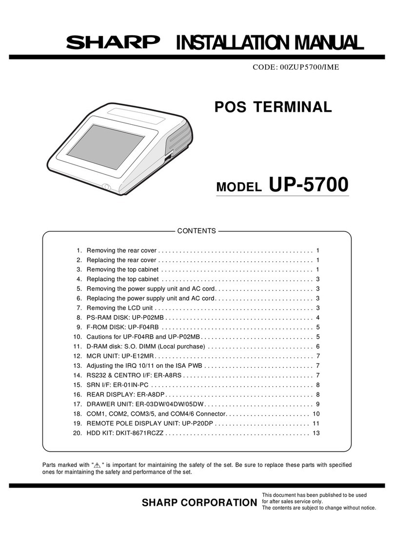
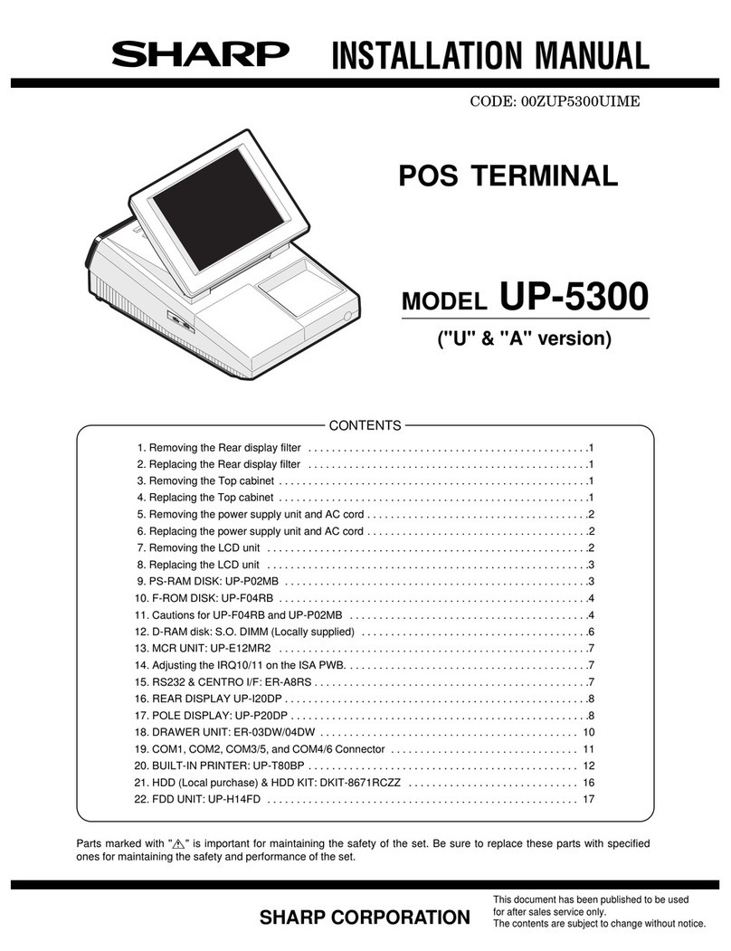
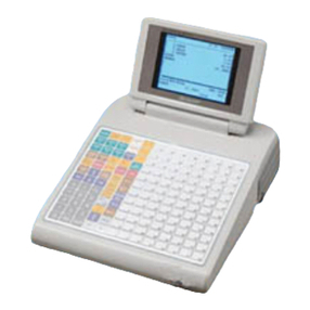
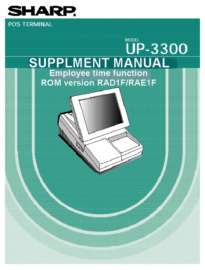
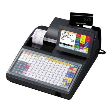
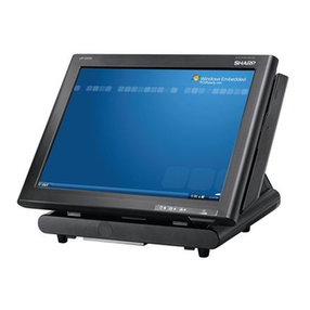
Sharp ER-A750 Owner's manual

PROGRAMMING
MANUAL
CODE: 00ZERA750UPME
POS TERMINAL
MODEL ER-A750
(For "U" version)
CHAPTER 1. SRV RESET (Program Loop Reset) and switch to SRV mode . . . 1
CHAPTER 2. MASTER RESET . . . . . . . . . . . . . . . . . . . . . . . . . . . . . . . . . . . . . . 2
CHAPTER 3. READING OF SRV MODE PROGRAM . . . . . . . . . . . . . . . . . . . . . 4
CHAPTER 4. SRV MODE PROGRAMMING . . . . . . . . . . . . . . . . . . . . . . . . . . . 14
CHAPTER 5. IRC SETTING . . . . . . . . . . . . . . . . . . . . . . . . . . . . . . . . . . . . . . . . 36
* For setting in PGM1 or PGM2 mode, refer to the Operation Manual.
CONTENTS
SHARP CORPORATION This document has been published to be used
for after sales service only.
The contents are subject to change without notice.

Major keys used in the SRV mode
The following major keys are used in the SRV mode.
FUNCTION KEY DESRIPTION
COURSOR UP ↑Moves cursor up
COURSOR DOWN ↓Moves cursor down
COURSOR RIGHT →Moves cursor right
COURSOR LEFT ←Moves cursor left
PAGE UP PAGE UP Moves page up
PAGE DOWN PAGE DOWN Moves page up
CLEAR CL Clear numeric entry or error message
CANCEL CANCEL Operaation cancel & back to previouse menu.
ENTER ENTER Data entry
ALL ENTER CA/AT All entry terminate.
TOGGLE SELECT “.” (DECIMAL POINT) Toggles between selections
OPEN SUB MENU SBTL Open sub menu

CHAPTER1. SRV RESET (Program
Loop Reset) and
switch to SRV mode
In the ER-A750, the following reset switch (location No.: S2) is used
to switch to the service (SRV) mode and to reset.
SRV. reset
Used to return the machine back to its operation state after a lock up
has occurred.
PROCEDURE
1) Turn off the AC switch.
2) Set the reset switch to “OFF” position
3) Turn on the AC switch.
4) Turn to “ON” the reset switch.
5) The SRV mode is displayed as shown below.
DISPLAY:
Reset
switch
1Side(Rear side):"ON" position(Reset state)
3Side(Front side):"OFF" position(Reset cancel)
– 1 –

CHAPTER 2. MASTER RESET
(All Memory Clear)
There are two possible methods to perform a master reset.
MRS-1 (Master resetting 1)
Used to clear all memory contents and return machine back to its
initial settings.
Return keyboard back to default for default kyeboard layout.
PROCEDURE
1) Turn off the AC switch.
2) Set the reset switch to “OFF” position
3) Turn on the AC switch.
4) While holding down MRS-1 key , turn to “ON” the reset switch.
* MRS-1 key : The key located on Left upper corner of the key-
board.
Keyboard layout
5) Enter the password key operation
DISPLAY:
ENTER PASSWORD
Password input procedure: Press the four corners of the key-
board in the sequence of a, b, c, and
d.
Keyboard layout
6) Master reset is started.
DISPLAY:
MASTER RESET
7) After completion of the master reset, the buzzer sounds three
times and the following SRV mode display is shown.
DISPLAY:
MRS-1 Key
a
c
db
– 2 –

MRS-2 (Master resetting 2)
Used to clear all memory and keyboard contents. This reset returns
all programming back to defaults.
The keyboard must be entered by hand. This reset is used if an
application needs different keyboard layout other than that supplied
by a normal MRS-1.
PROCEDURE
1) Turn off the AC switch.
2) Set the reset switch to “OFF” position
3) Turn on the AC switch.
4) While holding down MRS-2 key , turn to “ON” the reset switch.
* MRS-2 key : The key located on Right upper corner of the
keyboard.
Keyboard layout
5) Enter the password key operation
DISPLAY:
ENTER PASSWORD
Password input procedure: Press the four corners of the key-
board in the sequence of a, b, c, and
d.
Keyboard layout
6) Set the fixed keys in the table below. (Start from the zero “0” key,
The keys are displayed sequentially.)
DISPLAY:
ENTER 0 KEY
[Key setup procedure]
MRS-2
executed 0Key
position set Free key Setup
complete
0
Disable
NOTES:
*1: When the 0 key is pressed, the key of the key number on
display is disabled.
*2: Push the key on the position to be assigned. With this, the
key of the key number on display is assigned to that key
position.
*3: When relocating the keyboard, the PGM 1/2 mode use stan-
dard key layout.
Key
No. Key name Key
No. Key name Key
No. Key name
001 “0” key 011 “00” key 022 “CANCEL” key
002 “1” key 013 Decimal point “•” key 023 “ENTER” key
003 “2” key 014 “CL” key 024 “CA/AT” key
004 “3” key 015 “@/FOR” key
005 “4” key 016 “SBTL” key
006 “5” key 017 “MODE” key
007 “6” key 018 UP “↑” key
008 “7” key 019 DOWN “↓” key
009 “8” key 020 LEFT “←” key
010 “9” key 021 RIGHT “→” key
7) Master reset is started.
DISPLAY:
MASTER RESET
8) After completion of the master reset, the buzzer sounds three
times and the following SRV mode display is shown.
DISPLAY:
MRS-2 Key
a
c
db
– 3 –
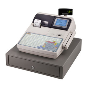
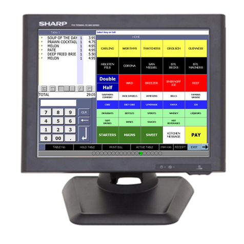
CHAPTER 3. READING OF SRV
PROGRAM
The setting contents of SRV mode can be checked with the display
or printer.
DISPLAY: SRV mode screen
Select “1 READING” and press the ENTER key.
↓
DISPLAY: READING item selection screen
Select the desired item, press the ENTER key.
↓
DISPLAY: OUTPUT lead destination select screen
Select the output destination, press the ENTER key.
↓
The setting content is displayed and printed.
Sample of program reports
1. [1 SYSTEM PRESET]
DISPLAY:
– 4 –

PRINTER:
Report title
JOB# / Data
– 5 –

2. [2 DEVICE ASSIGN]
DISPLAY:
PRINTER:
3. [3 FREE KEY LAYOUT]
DISPLAY:
Device name/Termiral No.
/Channel No.
Paper sheet type
Not assigned
Printer name
Auto cutter
– 6 –

– 7 –

– 8 –

PRINTER:
Key No. / Key text
/ Key position code
Not assigned
– 9 –

4. [4 FILE]
DISPLAY:
– 10 –

– 11 –

PRINTER:
File table No. / No. of records
/ No.of blocks
/ No. of used records
File memory start address
Memory end address
Empty memory start address
File table No. / No. of index
records-No. of data records
/ No. of used records
– 12 –

5. [5 SSP]
DISPLAY:
– 13 –

CHAPTER 4. SRV MODE
PROGRAMMING
DISPLAY: SRV mode screen
Select “2 SETTING” and press the ENTER key.
↓
DISPLAY: Setting item selection screen
Select the desired item and press the ENTER key.
↓
The item setting input screen is displayed.
1. [1 DEVICE ASSIGN]
DISPLAY: Setting item select screen
Select [1 DEVICE ASSIGN] and press the ENTER key.
↓
DISPLAY: DEVICE ASSIGN screen 1/2
↓“PAGE DOWN” key
DISPLAY: DEVICE ASSIGN screen 2/2
↓
Select the item to be changed and press the ENTER key.
The setting content is described below.
– 14 –

[1 DEVICE ASSIGN] - [1 J PRINTER]
- [2 R PRINTER]
- [3 BILL PRINTER]
- [4 REPORT PRINTER]
- [5 KP#1]
- [6 KP#2]
- [7 KP#3]
- [8 KP#4]
- [9 KP#5]
- [10 KP#6]
- [11 KP#7]
- [12 KP#8]
- [13 KP#9]
DISPLAY: Setting screen
DISPLAY TEXT CONTENTS SELECT ITEM MRS NOTE
TERMINAL# Terminal number 000 ∼254 000 000: Self terminal No.
This means local device.
1-254: Except self terminal No.
This means re-routed device.
Re-routing programming is only valid for printer.
CHANNEL# Channel number 0 ∼7 0 0: No RS-232 channel is assigned.
PRINTER NAME Connected printer name EPSON TM-T85 ★
SHARP ER-03/04RP When this machine is used as a “report printer” of a bulky
data report such as PLU report, printing will be cut midway
automatically on the side of the ER-03/04RP when the
printing time reaches the time-out (about 30 sec). After that,
however, printing will be resumed automatically to complete
printing of the report.
EPSON TM-300
EPSON TM-T80
RESERVED
AUTO CUTTER Auto cutter function No ★
Yes
PAPER SHEET Paper sheet type setting ONESHEET ★
TWO SHEET
[1 DEVICE ASSIGN] - [14 CAT#1]
- [15 CAT#2]
- [16 CAT#3]
- [17 SCALE]
- [18 COIN DISP.]
- [19 ONLINE]
- [20 CVM DATA I/F]
DISPLAY TEXT CONTENTS SELECT ITEM MRS NOTE
TERMINAL# Terminal number 000 ∼254 000 000: Self terminal No.
This means local device.
1-254: Except self terminal No.
This means re-routed device.
Re-routing programming is only valid for printer.
CHANNEL# Channel number 0 ∼7 0 0: No RS-232 channel is assigned.
– 15 –

2. [2 SYSTEM PRESET]
DISPLAY: Setting item select screen
Select “1 SYSTEM PRESET” and press the ENTER key.
↓
DISPLAY: SYSTEM RESET screen 1/3
↓“PAGE DOWN” key
DISPLAY: SYSTEM RESET screen 2/3
↓“PAGE DOWN” key
DISPLAY: SYSTEM PRESET screen 3/3
Select the job # to be changed and enter the value.
The content of each jog is described below.
[JOB#901] : MRS=0002
901-A,B: Not used (Fixed at “00”)
901-C: 1.Rounding system
1.Rounding system 901-C
Normal 0 ★
Singapole 8
901-D: 1.TAB setting
1.TAB setting 901-D
0.0 1
0.00 2 ★
0.000 3
[JOB#902] : MRS=0000
902-A: 1.In-line system
1.In-line system 902-A
No 0 ★
Yes 1
902-B,C,D: Not used (Fixed at “000”)
[JOB#903] : MRS=4000
903-A: 1.IR (ECR data copy) baud rate
1.IR baud rate 903-A
2400 2
4800 3
9600 4 ★
19200 5
38400 6
57600 7
115200 8
903-B: 1.Symbol of scale entry
1.Symbol of scale entry 903-B
“LB” 0 ★
“KG” 2
– 16 –

903-C: 1.Scale entry system
2.Entry of tare
3.Unit of weight for the scale
1.Scale entry
system 2.Entry of tare 3.Unit of weight
for the scale 903-C
Manual Disallowed 2id(3id)+2dd 0 ★
1id(2id)+3dd 1
Allowed 2id(3id)+2dd 2
1id(2id)+3dd 3
Automatic Disallowed 2id(3id)+2dd 4
1id(2id)+3dd 5
Allowed 2id(3id)+2dd 6
1id(2id)+3dd 7
903-D: Not used (Fixed at “0”)
[JOB#904] : MRS=0000
904-A: 1.Printing of date
1.Printing of date 904-A
Yes 0 ★
No 4
904-B: 1.Printing of the consecutive No.
1.Printing of the consecutive No. 904-B
Yes 0 ★
No 4
904-C,D: Not used (Fixed at “00”)
[JOB#905] : MRS=0005
905-A: 1.Taxable 4 subtotal print on X/Z report
2.Gross Tax 4 and refund Tax 4 total print on X/Z report
3.Net Tax 4 total print on X/Z report
1.Taxable 4
subtotal 2.Gross Tax 4
and refund
Tax 4 total
3.Net Tax 4 total 905-A
Print Print Print 0 ★
Skip 1
Skip Print 2
Skip 3
Skip Print Print 4
Skip 5
Skip Print 6
Skip 7
905-B: 1.Tax printing when taxable subtotal is zero.
2.Tax printing when tax is zero.
1.Tax printing when
taxable subtotal is zero. 2.Tax printing when
tax is zero. 905-B
Skip Print 0 ★
Skip 1
Print Print 4
Skip 5
905-C, D: Not used (Fixed at “00”)
[JOB#906] : MRS=0031
906-A: 1.Printing of Dept. and PLU code
2.Entry which makes the PLU stock counter negative
1.Printing of Dept.
and PLU code 2.Entry which makes the PLU
stock counter negative 906-A
No
Allowed unconditionally 0 ★
Operation allowed despite
error message 1
Inhibited 2
Yes
Allowed unconditionally 4
Operation allowed despite
error message 5
Inhibited 6
906-B: 1.Hash department setting
1.Hash department setting 906-B
Enable 0 ★
Disable 2
906-C: 1.Split pricing counting
2.Multiplication entry
1.Split pricing
counting 2.Multiplication entry 906-C
Quantity Multiplication 0
Split pricing 2
Ffx (FF sequence + Split pricing) 3 ★
Package Multiplication 4
Split pricing 6
Ffx (FF sequence + Split pricing) 7
906-D: 1.Presetting of consective No.
2.Fractional quantity
1.Presetting of
consective No. 2.Fractional quantity 906-D
Disable No 0
Yes (3 digit decimal place) 1 ★
Enable No 2
Yes (3 digit decimal place) 3
[JOB#907] : MRS=0010
907-A,B: Not used (Fixed at “00”)
907-C: 1.Minus Dept./PLU
1.Minus Dept./PLU 907-C
Disable 0
Enable 1 ★
907-D: Not used (Fixed at “0”)
– 17 –

[JOB#908] : MRS=0000
908-A: GT print on Z report
GT1 (NET) GT2 (+) GT3 (–) 908-A
Print Print Print 0 ★
Skip 1
Skip Print 2
Skip 3
Skip Print Print 4
Skip 5
Skip Print 6
Skip 7
908-B: GT print on X report
GT1 (NET) GT2 (+) GT3 (–) 908-B
Skip Skip Skip 0 ★
Print 1
Print Skip 2
Print 3
Print Skip Skip 4
Print 5
Print Skip 6
Print 7
908-C: 1.Add void -mode transaction data to hourly total report
2.Resetting of consective number in Z1 resetting
1.Add void -mode
transaction data to
hourly total report
2.Resetting of
consective number in
Z1 resetting 908-C
No No 0 ★
Yes 1
Yes No 4
Yes 5
908-D: 1.Printing of X/Z report
2.Z1 resetting that resets GT
1.Printing of X/Z report 2.Z1 resetting that resets GT 908-D
Receipt & Journal Disable 0 ★
Enable 1
Journal only Disable 4
Enable 5
[JOB#909] : MRS=2000
909-A: 1.Printing of training GT on the X report
2.Printing of training GT on the Z report
1.Printing of training
GT on the X report 2.Printing of training GT on
the Z report 909-A
Skip Print 0
Skip 1
Print Print 2 ★
Skip 3
909-B: 1.Printing of data on PLU resetting report
1.Printing of data on PLU resetting report 909-B
Print 0 ★
Skip 4
909-C: 1.Printing of VOID mode totalizer and MGR VOID totalizer
on Z2 report
2.Printing of VOID mode totalizer and MGR VOID totalizer
on Z1 report
1.Printing of VOID
mode totalizer and
MGR VOID totalizer
on Z2 report
2.Printing of VOID mode
totalizer and MGR VOID
totalizer on Z1 report 908-C
Print Print 0 ★
Skip 2
Skip Print 4
Skip 6
909-D: Not used (Fixed at “0”)
[JOB#910] : MRS=0024
910-A: 1. Drawer open at server sign ON/OFF
1. Drawer open at server sign ON/OFF 910-A
No 0 ★
Yes 2
910-B: Not used (Fixed at ”0”)
910-C: 1.Server # entry system
2.Server # entry system 910-C
Stay down 0
Auto sign off 2 ★
910-D: Not used (Fixed at “4”)
[JOB#911] : MRS=0000
911-A: 1. Fraction treatment
1. Fraction treatment 911-A
Round off 0 ★
Round up 1
Round down 2
911-B, C: Not used (Fixed at “00”)
911-D: 1.RECEIPT/SLIP header format
1.RECEIPT/SLIP header format 911-D
Format 1 0 ★
Format 2 2
Format 3 4
– 18 –
Other manuals for ER-A750
3
Table of contents
Other Sharp Touch Terminal manuals

Sharp
Sharp ZQ-5000 User manual

Sharp
Sharp UP-V5500 User manual

Sharp
Sharp ER-A850 User manual

Sharp
Sharp UP-820N User manual

Sharp
Sharp ER-A770 User manual

Sharp
Sharp ER-A770 User manual

Sharp
Sharp RZ-X650 User manual

Sharp
Sharp UP-X300 User manual

Sharp
Sharp UP-3300 Owner's manual

Sharp
Sharp UP-3500 User manual