E
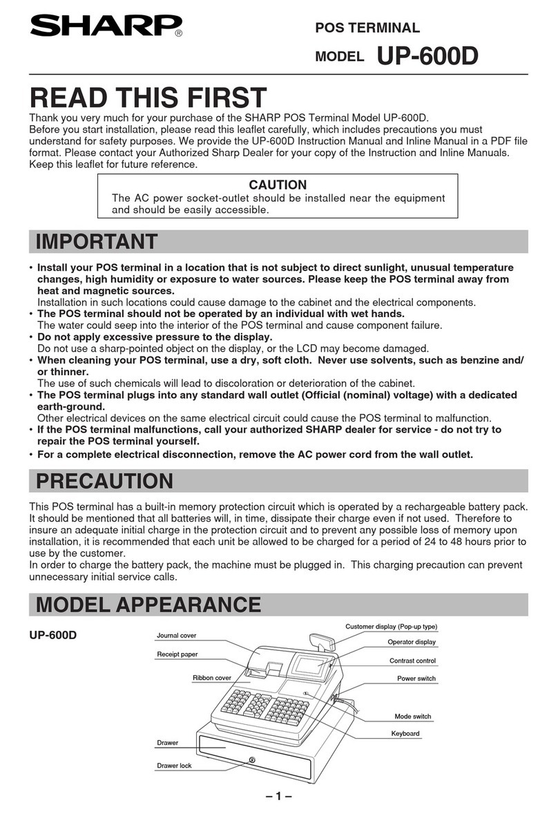
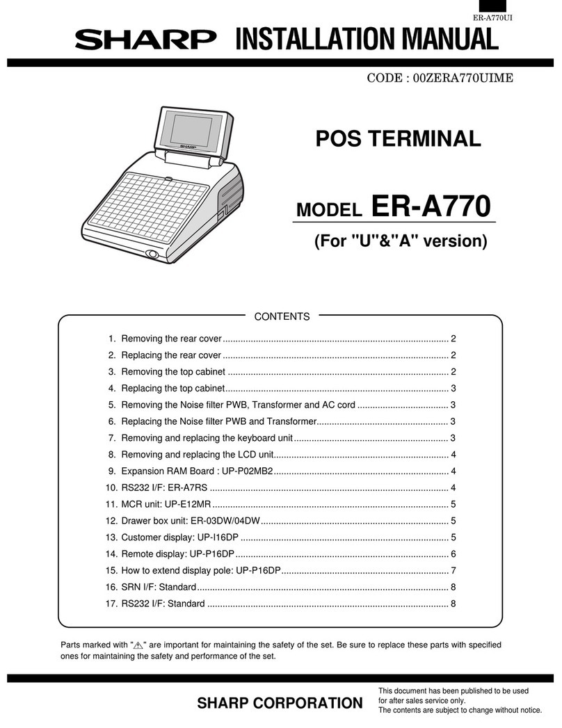
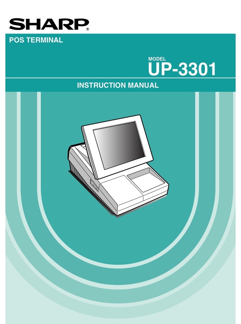
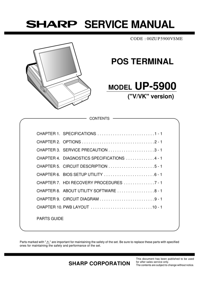
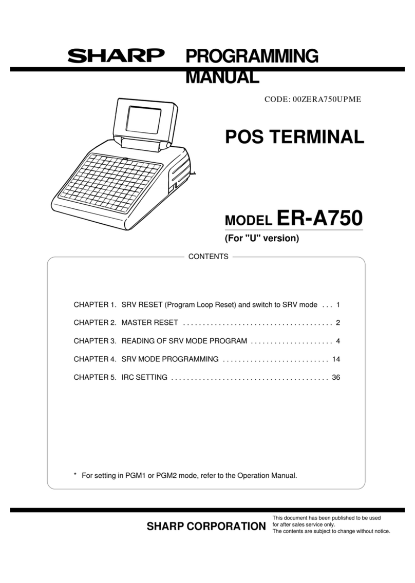
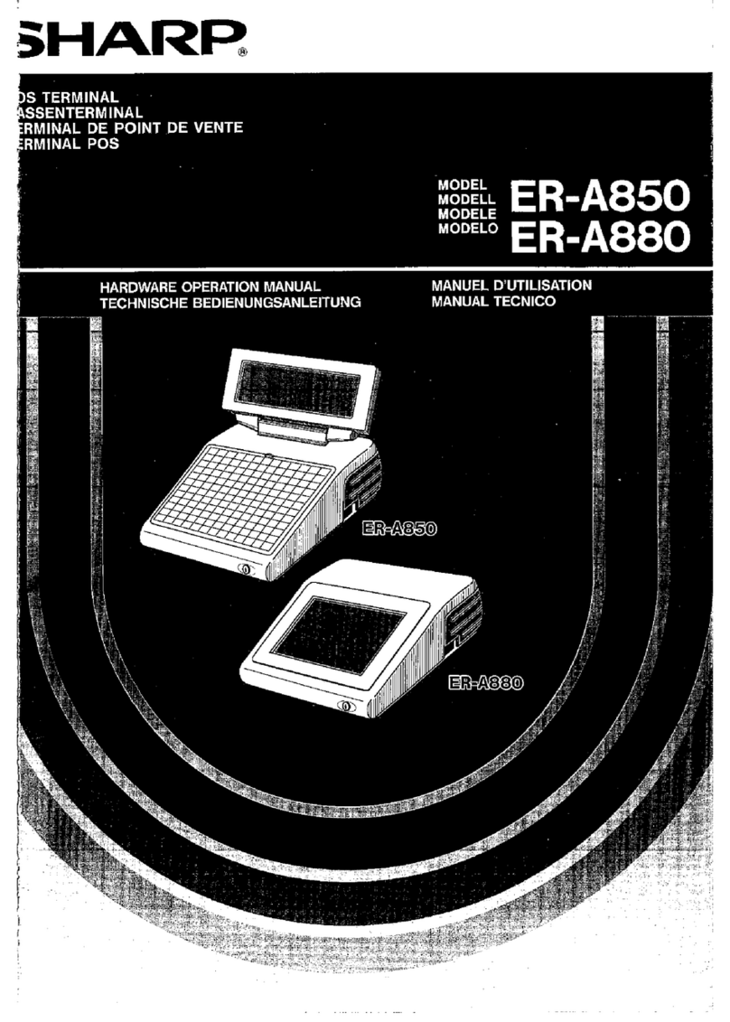
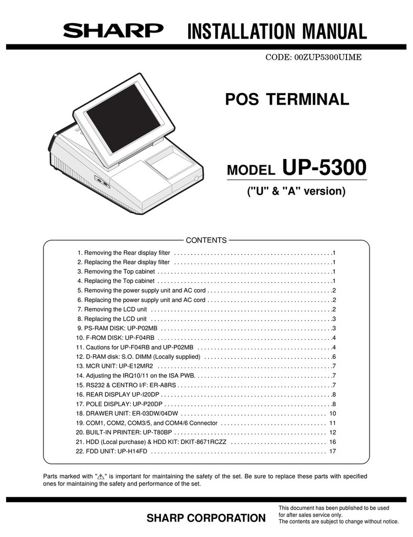
SHARP INSTALLATIONMANUAL
CODE: OOZERA750WME
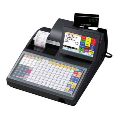
POS TERMINAL
MODELER-A750
(For “V”version)
/CONTENTS \
1. Removingthe rear cover. ....................................................1
2. Replacingthe rear cover .....................................................1
3.
4.
5.
6.
7.
8.
9.
10.
11.
12.
13.
14.
Removingthe top cabinet ....................................................1
Replacingthe top cabinet ....................................................1
Removingthe reardisplay . . . . . . . . . . . . . . . . . . . . . . . . . . . . . . . . . . . . . . . . . . . ........2
Removing the NoisefilterPWB, TransformerandAC cord ..........................2
Replacingthe Noise filter PWB and Transformer ..................................2
Removing and replacing the keyboard unit.... ...................................3
Removing and replacing the LCD unit (ER-A750) ..........................,,.....3
ER-03MB&ER-04MB ......................................................4
Precautions in installing optional RAM PUBS .....................................4
ER-A7RS ..........................................................,.....5
ER-A8MR ................................................................6
ER-03DW/04DW. ..........................................................6
15. Connecting the RS-232connectorand theSRN connector (standard pafis) ............7
16. Cable wiring ..............................................................7
17. RS-232connecting devicecablewiring diagram ..................................8
\J
Parts marked with “~” is important for maintaining the safety of the set Be sure to replacethesePanswithspecified ones for
maintaining thesafe~and performance oftheset.
Thisdocument hasbeenpub~sh~ tobeused
SHARP CORPORATION ‘era’ersa’esse’’’iceon”
~econtents are subje~to change withoutnotice.
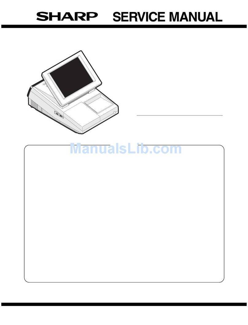
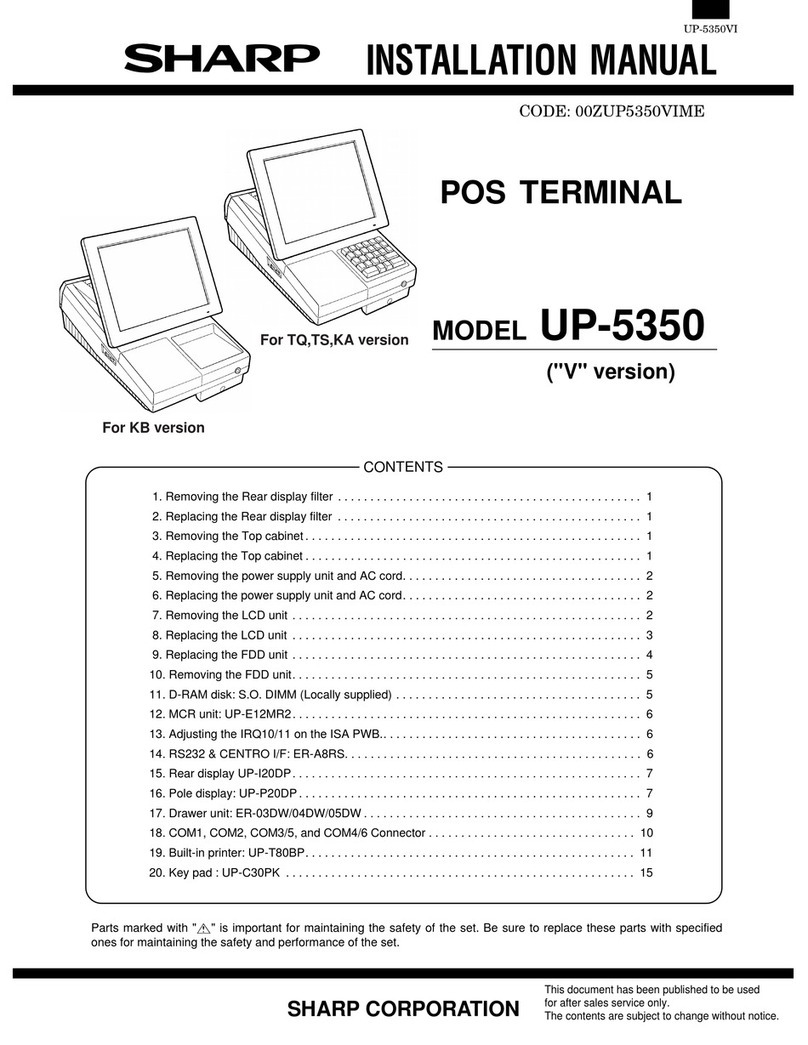
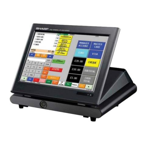
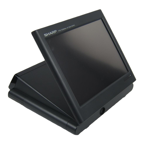
Sharp ER-A750 installation ManualSharp ER-A750 installation ManualSharp ER-A750 installation ManualSharp ER-A750 installation Manual
