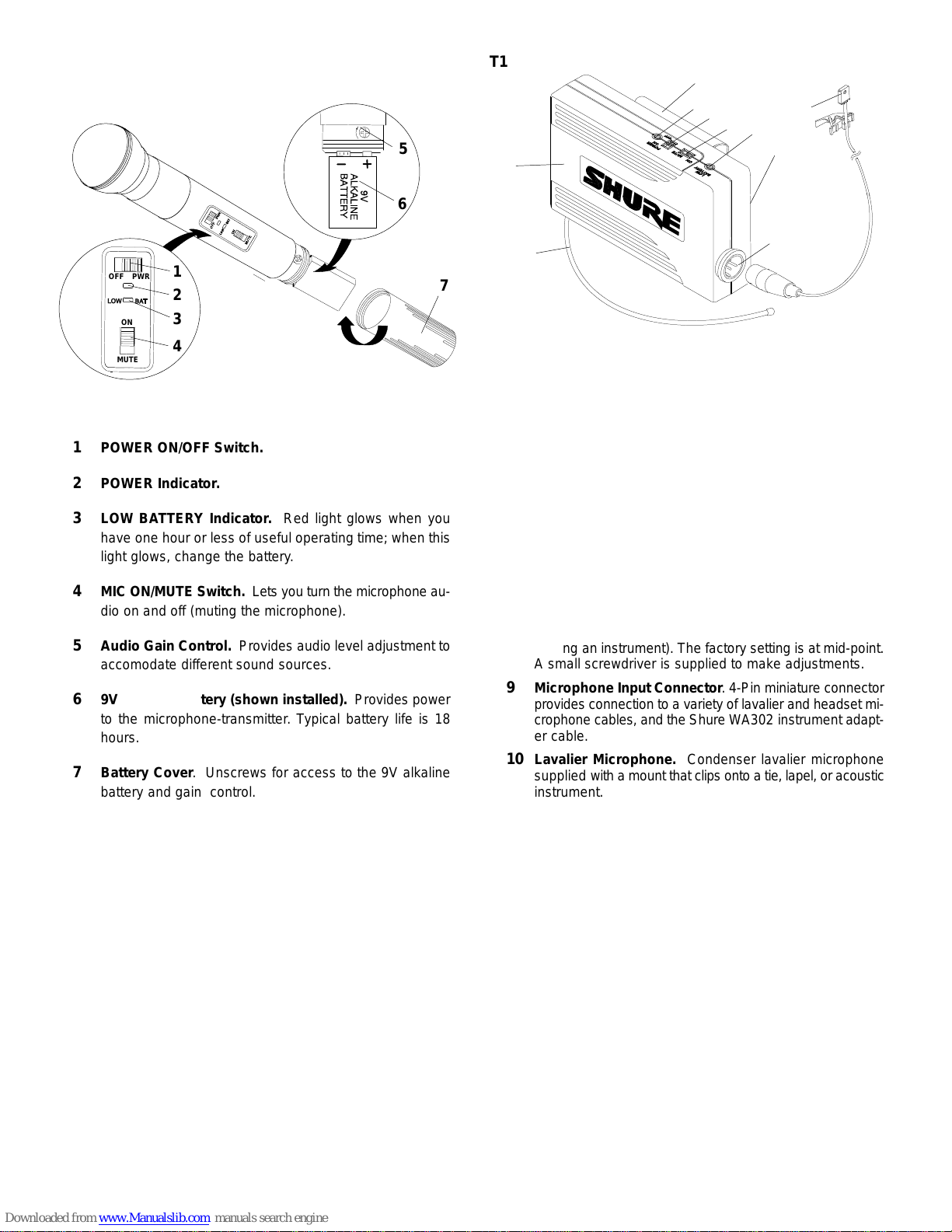
Shure The Twin Pro User manual

The Twin Prot
Wireless Microphone System User Guide
The Twin Pro Wireless Microphone System
User Guide
27C8642 (BG)
2002, Shure Incorporated Printed in U.S.A.

TABLE OF CONTENTS –– ENGLISH
Introduction English – 1. . . . . . . . . . . . . . . . . . . . . . . . . . . . . . . . . . . . . . . . . . . . . . . . . . . . . . . . . . . . . . . . . . . . . . . . . . .
Description English – 1. . . . . . . . . . . . . . . . . . . . . . . . . . . . . . . . . . . . . . . . . . . . . . . . . . . . . . . . . . . . . . . . . . . . . . . . . . .
Using the T88 Wireless Receiver English – 3. . . . . . . . . . . . . . . . . . . . . . . . . . . . . . . . . . . . . . . . . . . . . . . . . . . . . . . .
Using the T2 Hand-Held Microphone Transmitter English – 3. . . . . . . . . . . . . . . . . . . . . . . . . . . . . . . . . . . . . . . . .
Using the T1 Body-Pack Transmitter English – 4. . . . . . . . . . . . . . . . . . . . . . . . . . . . . . . . . . . . . . . . . . . . . . . . . . . .
Tips and Troubleshooting English – 5. . . . . . . . . . . . . . . . . . . . . . . . . . . . . . . . . . . . . . . . . . . . . . . . . . . . . . . . . . . . . .
Specifications and Information English – 6. . . . . . . . . . . . . . . . . . . . . . . . . . . . . . . . . . . . . . . . . . . . . . . . . . . . . . . . .

1
English –
INTRODUCTION
The Twin ProtWireless System is the finest in its class. This
system will give you excellent performance for years to come.
System Contents
The Twin Pro Wireless System contains the following compo-
nents:
•One T88 dual channel wireless receiver
•Two transmitters available in one of three different combina-
tions (see System Combinations below)
•One PS20 (120 Vac) or PS20E (230 Vac) power adapter
•One plastic screwdriver for squelch adjustment
System Combinations
The Twin Pro system includes one of the following three trans-
mitter combinations:
•Two handheld microphone transmitters (includes two swivel
adapters and two anti-roll devices)
or
•Two body-pack transmitters with lavalier microphones
or
•One handheld microphone and one body-pack transmitter (in-
cludes one swivel adapter and one anti-roll device)
DESCRIPTION
T88 Wireless Receiver (Figure 1)
FIGURE 1
FRONT
BACK
1234
5
1234
6
77
5
1Power Indicators.
2RF Signal Indicators. Yellow indicates when RF (radio
frequency) signals are received from the transmitter.
3Audio Peak Indicators. These lights flicker occasionally
in normal operation. They are ON steadily when the audio
input is overloaded.
4Volume Controllers. Controls the audio output level.
5Telescoping Antennas. Receive signals from the trans-
mitters. Make sure the antennas are fully extended verti-
cally.
6Power Input Connector. Connects to a PS20 (120 Vac)
or PS20E (230 Vac) power adapter.
7Independent Audio Output Connectors. There is a sep-
arate, unbalanced 1/4-inch phone jack for each channel.

2
English –
T2 Handheld Microphone Transmitter (Figure 2)
FIGURE 2
ÁÁÁÁ
ÁÁÁÁ
ÁÁÁ
ÁÁÁ
ÁÁÁ
ÁÁÁ
ÁÁÁ
Á
Á
ÁÁ
ÁÁ
ÁÁ
ÁÁ
ÁÁÁÁÁÁ
ÁÁÁÁÁÁ
ÁÁÁÁÁÁ
ÁÁÁÁÁÁ
ÁÁÁÁÁÁ
ÁÁÁÁÁÁ
Á
ÁÁ
ÁÁÁ
ÁÁÁ
ÁÁÁ
ÁÁÁ
ÁÁÁ
ÁÁÁ
ÁÁÁ
ÁÁÁ
ÁÁÁ
ÁÁÁ
ÁÁ
ÁÁ
ÁÁÁ
ÁÁÁ
ÁÁÁ
Á
Á
ÁÁ
ÁÁ
ÁÁÁ
ÁÁÁ
ÁÁ
ÁÁ
ÁÁ
ÁÁ
Á
Á
ÁÁÁ
ÁÁÁ
ÁÁÁ
ÁÁÁ
ÁÁÁ
ÁÁÁ
ÁÁÁ
ÁÁÁ
ÁÁÁ
ÁÁÁ
ÁÁÁ
ÁÁÁ
ÁÁÁ
ÁÁ
ÁÁÁ
ÁÁÁ
ÁÁÁ
ÁÁ
ÁÁ
ÁÁ
ÁÁ
Á
Á
Á
Á
Á
ÁÁ
Á
Á
Á
Á
Á
Á
Á
Á
Á
Á
Á
Á
Á
Á
Á
Á
Á
Á
Á
Á
Á
Á
Á
Á
Á
Á
Á
Á
Á
Á
Á
Á
Á
Á
Á
Á
Á
Á
Á
Á
Á
ÁÁÁÁ
Á
Á
Á
Á
Á
Á
ÁÁÁ
ÁÁ
Á
ÁÁÁ
Á
Á
Á
Á
Á
Á
Á
Á
Á
Á
Á
Á
Á
Á
Á
Á
ÁÁ
Á
Á
Á
Á
ÁÁ
Á
Á
Á
Á
Á
Á
Á
Á
Á
Á
Á
Á
ÁÁ
ÁÁÁ
Á
ÁÁ
ÁÁÁÁ
Á
Á
Á
Á
Á
Á
Á
Á
Á
Á
Á
Á
Á
Á
Á
Á
Á
Á
Á
ÁÁÁ
Á
ÁÁÁÁÁ
ÁÁÁ
ÁÁÁÁ
Á
ÁÁ
ÁÁÁ
ÁÁÁÁ
Á
Á
Á
ÁÁ
Á
Á
ÁÁ
ÁÁ
ÁÁÁÁÁÁ
ÁÁ
ÁÁÁÁÁÁ
Á
Á
Á
MUTE
ON
OFF PWR
ÁÁÁ
ÁÁÁ
ÁÁÁ
ÁÁÁ
ÁÁÁÁ
ÁÁÁ
ÁÁÁ
ÁÁÁ
ÁÁÁ
ÁÁÁ
ÁÁÁ
Á
Á
Á
Á
Á
ÁÁÁÁ
Á
Á
Á
Á
ÁÁÁÁÁ
Á
ÁÁÁ
Á
Á
Á
Á
Á
Á
ÁÁ
ÁÁ
ÁÁ
ÁÁ
ÁÁ
Á
Á
ÁÁ
Á
Á
Á
ÁÁ
Á
Á
Á
Á
ÁÁ
Á
Á
ÁÁ
Á
ÁÁ
ÁÁ
ÁÁ
Á
ÁÁ
ÁÁ
Á
Á
Á
Á
Á
Á
Á
Á
Á
ÁÁ
ÁÁ
ÁÁ
ÁÁ
Á
Á
Á
ÁÁ
ÁÁ
Á
Á
Á
Á
Á
Á
ÁÁ
ÁÁ
ÁÁ
Á
Á
ÁÁÁÁÁÁÁÁÁÁÁÁÁÁ
ÁÁÁ
ÁÁÁÁÁÁÁ
ÁÁÁ
Á
Á
Á
Á
Á
Á
ÁÁ
Á
Á
Á
Á
Á
Á
Á
Á
Á
1
2
3
4
5
6
7
1POWER ON/OFF Switch.
2POWER Indicator.
3LOW BATTERY Indicator. Red light glows when you
have one hour or less of useful operating time; when this
light glows, change the battery.
4MIC ON/MUTE Switch. Lets you turn the microphone au-
dio on and off (muting the microphone).
5Audio Gain Control. Provides audio level adjustment to
accomodate different sound sources.
69V Alkaline Battery (shown installed). Provides power
to the microphone-transmitter. Typical battery life is 18
hours.
7Battery Cover. Unscrews for access to the 9V alkaline
battery and gain control.
T1 Body-Pack Transmitter (Figure 3)
FIGURE 3
Á
Á
Á
Á
Á
Á
Á
Á
ÁÁ
ÁÁ
ÁÁÁÁÁ
ÁÁÁÁÁ
ÁÁÁÁÁ
ÁÁ
Á
Á
Á
Á
Á
Á
Á
Á
Á
Á
Á
Á
Á
Á
Á
Á
Á
Á
Á
ÁÁ
ÁÁ
Á
Á
Á
Á
Á
Á
Á
Á
Á
Á
ÁÁ
ÁÁ
Á
Á
Á
Á
Á
Á
ÁÁ
ÁÁ
ÁÁ
ÁÁ
Á
Á
ÁÁ
Á
ÁÁ
Á
Á
Á
ÁÁ
ÁÁ
ÁÁ
ÁÁ
Á
Á
Á
Á
Á
Á
ÁÁ
ÁÁ
Á
Á
ÁÁ
Á
Á
Á
ÁÁ
Á
ÁÁÁÁÁ
ÁÁÁÁÁ
ÁÁÁÁÁ
Á
Á
ÁÁ
ÁÁ
Á
Á
Á
Á
Á
Á
Á
Á
ÁÁ
Á
Á
Á
ÁÁÁÁÁÁ
ÁÁÁÁÁÁ
ÁÁÁÁÁÁ
ÁÁÁÁÁÁ
ÁÁÁÁÁÁ
ÁÁÁÁÁÁ
ÁÁÁÁÁÁ
ÁÁÁÁÁÁ
Á
ÁÁÁÁÁÁ
ÁÁÁÁÁÁ
ÁÁÁÁÁÁ
ÁÁÁÁÁÁ
Á
Á
Á
Á
Á
Á
Á
ÁÁÁÁÁÁ
ÁÁÁÁÁÁ
ÁÁÁÁÁÁ
ÁÁÁÁÁÁ
ÁÁÁÁÁÁ
ÁÁÁÁÁÁ
ÁÁÁÁÁÁ
ÁÁÁÁÁÁ
ÁÁÁÁÁÁÁÁ
ÁÁÁÁÁÁÁÁ
ÁÁÁÁÁÁÁÁ
ÁÁÁÁÁÁÁÁ
ÁÁÁÁÁÁÁÁ
ÁÁÁÁ
ÁÁÁÁ
ÁÁÁÁ
ÁÁÁÁ
ÁÁÁÁ
ÁÁÁÁ
ÁÁÁÁÁ
ÁÁÁÁÁ
ÁÁÁÁÁ
ÁÁÁÁÁ
ÁÁÁÁÁ
ÁÁÁÁÁ
ÁÁÁÁÁ
Á
Á
Á
Á
ÁÁÁÁÁÁ
ÁÁÁÁÁÁ
ÁÁÁÁÁÁ
ÁÁÁÁÁÁ
ÁÁÁÁÁÁ
ÁÁÁÁÁÁ
ÁÁÁÁÁÁ
ÁÁÁÁÁÁ
ÁÁÁÁÁ
ÁÁÁÁÁ
ÁÁÁÁÁ
ÁÁÁÁÁÁ
ÁÁÁÁÁÁ
ÁÁÁÁÁÁ
ÁÁÁÁÁ
ÁÁÁÁÁ
ÁÁÁÁÁ
ÁÁÁÁÁ
ÁÁÁÁ
ÁÁÁÁ
ÁÁÁÁ
ÁÁÁÁÁ
ÁÁÁÁÁ
ÁÁÁÁÁ
ÁÁÁÁÁ
ÁÁÁÁÁ
ÁÁÁÁÁ
ÁÁÁÁÁÁ
ÁÁÁÁÁÁ
ÁÁÁÁÁÁ
ÁÁÁÁÁÁ
ÁÁÁÁÁÁ
ÁÁÁÁÁÁ
ÁÁÁÁÁÁ
ÁÁÁÁÁÁ
ÁÁÁÁÁÁ
ÁÁÁÁÁÁ
ÁÁÁÁÁÁ
ÁÁÁÁÁÁ
ÁÁÁÁÁÁ
ÁÁÁÁÁÁ
ÁÁÁÁÁÁ
ÁÁÁÁÁÁ
Á
Á
Á
Á
Á
Á
Á
Á
Á
Á
Á
Á
Á
Á
Á
Á
Á
Á
Á
Á
Á
ÁÁ
Á
ÁÁ
ÁÁ
ÁÁ
1
2
3
45678
9
10
1Battery Compartment.
2Antenna.For best operation, the antenna must hang ver-
tically, and should not be coiled or bundled.
3Belt Clip.
4POWER Indicator.
5POWER ON/OFF Switch.
6Audio ON/MUTE Switch. Mutes the transmitter to pre-
vent unwanted sounds from being picked up by the receiv-
er without turning the transmitter off.
7LOW BATTERY Indicator. When this red light is glowing,
you have one hour or less of useful operating time; change
the battery.
8Audio Gain Control. Provides audio level adjustment to
accommodate different sound sources (e.g., speaking or
playing an instrument). The factory setting is at mid-point.
A small screwdriver is supplied to make adjustments.
9Microphone Input Connector. 4-Pin miniature connector
provides connection to a variety of lavalier and headset mi-
crophone cables, and the Shure WA302 instrument adapt-
er cable.
10 Lavalier Microphone. Condenser lavalier microphone
supplied with a mount that clips onto a tie, lapel, or acoustic
instrument.

3
English –
USING THE T88 WIRELESS RECEIVER
Connecting the T88 Wireless Receiver
Á
Á
Á
Á
Á
Á
Á
Á
Á
ÁÁ
ÁÁÁ
Á
ÁÁÁ
ÁÁÁ
ÁÁÁ
ÁÁÁ
Á
ÁÁ
Á
Á
Á
T88 BACK
AUDIO MIXER
or KARAOKE UNIT
Á
Á
Á
Á
Á
Á
Á
Á
Á
Á
ÁÁ
Á
ÁÁÁ
ÁÁÁÁ
ÁÁÁ
ÁÁÁ
Á
ÁÁ
Á
Á
Á
Á
FIGURE 4
AC ADAPTER
1. Connect the receiver outputs for channels 1 and 2 to the
mixer or karoake unit using unbalanced, single-conduc-
tor, shielded cables with 1/4-inch phone plugs.
2. Connect the ac adapter to the POWER jack on the rear
panel of the receiver.
3. Plug the ac adapter into an appropriate power outlet.
Squelch Adjustment
FIGURE 5
DECREASE INCREASE
SQUELCH
The receiver squelch control is factory preset at the 12
o’clock position for optimum performance. No further ad-
justment is normally required. However, it is possible to ad-
just the squelch control to emphasize either signal quality or sys-
tem range.
•To raise the squelch threshold, rotate the control clockwise. This
causes the receiver to demand a higher quality signal (less noise
before muting), but it reduces the operating range.
•To lower the squelch threshold, rotate the control counterclock-
wise. This allows a lower quality signal through (more noise
before muting), but it extends the operating range.
USING THE T2 HAND HELD MICROPHONE
TRANSMITTERS
Operating the T2 Hand Held Microphone Transmitters
1. Press the POWER switch on the T88 receiver ON.
2. Slide the transmitter POWER ON/OFF switch to the ON
position. Check the battery level. If the LOW BATTERY indi-
cator is lit, see Transmitter Battery Installation.
3. Check the RF indicator on the T88 receiver to see if the
radio signal is being received.
4. Slide the MIC ON/MUTE switch to the ON position and
begin speaking or singing.
NOTE: If the red PEAK light on the receiver does not flicker
during the loudest sounds, the transmitter gain may need to
be increased. See the Transmitter Audio Gain Adjustment
section.
5. During the performance or presentation, slide the MIC
ON/MUTE switch to the MUTE position when the micro-
phone is not being used.
6. When the performance or presentation is over, slide the
transmitter POWER ON/OFF switch to the OFF position
to conserve battery power.
Á
Á
Á
Á
Á
Á
Á
Á
Á
Á
Á
Á
ÁÁ
ÁÁ
ÁÁ
ÁÁ
Á
Á
Á
Á
ÁÁ
ÁÁ
ÁÁ
Á
Á
Á
Á
ÁÁ
Á
Á
Á
Á
Á
Á
Á
Á
ÁÁÁÁ
Á
Á
Á
Á
ÁÁÁÁÁ
Á
ÁÁÁ
Á
Á
Á
Á
Á
Á
Á
Á
Á
Á
Á
Á
Á
Á
ÁÁ
Á
Á
Á
Á
ÁÁ
Á
Á
Á
Á
Á
Á
Á
Á
ÁÁ
Á
Á
Á
ÁÁ
Á
Á
Á
Á
Á
Á
Á
Á
Á
Á
Á
ÁÁÁÁÁÁÁÁÁÁÁÁÁÁÁÁÁÁÁÁÁÁÁÁÁÁÁÁÁÁÁ
Á
Á
Á
Á
ÁÁÁÁÁÁÁ
ÁÁ
Á
ÁÁ
Á
Á
Á
Á
Á
Á
Á
Á
Á
Á
Á
Á
Á
Á
Á
FIGURE 6
T2
TRANSMITTERS
T88
RECEIVER
Á
Á
Á
Á
Á
Á
Á
Á
Á
Á
Á
Á
ÁÁ
ÁÁ
ÁÁ
Á
Á
Á
Á
Á
Á
Á
Á
Á
Á
Á
Á
Á
Á
Á
Á
Á
ÁÁ
ÁÁÁÁÁ
Á
Á
Á
Á
Á
Á
Á
Á
Á
Á
Á
Á
Á
Á
Á
Á
Á
Á
Á
Á
Á
ÁÁ
ÁÁ
ÁÁ
ÁÁ
ÁÁ
ÁÁ
Á
Á
Á
ÁÁÁÁÁÁ
Á
Á
ÁÁÁÁÁ
Á
Á
Á
Á
Á
Á
Á
Á
Á
Á
Á
Á
Á
Á
Á
ÁÁÁ
Á
Á
ÁÁÁ
Á
Á
Á
Á
Á
Á
Á
ÁÁ
Á
Á
Á
ÁÁ
Á
Á
Á
Á
Á
Á
Á
Á
Á
Á
Á
ÁÁÁÁÁÁÁÁÁÁÁÁÁÁÁÁÁÁÁÁÁÁÁÁÁÁÁÁÁÁÁ
Á
Á
Á
Á
ÁÁÁÁÁÁÁ
ÁÁ
Á
ÁÁ
Á
Á
Á
Á
Á
Á
Á
Á
Á
Á
Á
Á
Á
Á
Á
Á
Á
Á
Á
Á
Á
Á
Á
Á
Á
Á
Á
Á
Á
Á
Á
Á
Á
ÁÁ
ÁÁÁÁÁ
Á
Á
Á
Á
Á
Á
Á
Á
Á
Á
Á
Á
Transmitter Battery Installation
1. Slide the transmitter POWER ON/OFF switch to the OFF
position.
2. Unscrew the transmitter battery cover to expose the bat-
tery terminals, as shown in Figure 7.
ÁÁÁ
Á
Á
ÁÁ
Á
Á
ÁÁÁ
ÁÁÁ
Á
Á
Á
Á
Á
ÁÁ
Á
ÁÁ
Á
Á
Á
ÁÁ
ÁÁ
ÁÁ
ÁÁ
ÁÁ
ÁÁ
Á
ÁÁÁ
Á
Á
ÁÁ
ÁÁ
ÁÁÁÁ
ÁÁ
Á
ÁÁ
ÁÁ
ÁÁ
ÁÁ
Á
ÁÁ
ÁÁ
ÁÁ
ÁÁ
ÁÁ
Á
Á
ÁÁ
Á
Á
Á
Á
Á
Á
Á
Á
Á
Á
Á
Á
Á
Á
Á
Á
Á
Á
Á
Á
Á
Á
Á
Á
Á
Á
Á
Á
Á
Á
Á
Á
Á
Á
Á
Á
Á
+
-
FIGURE 7
3. Insert a fresh 9V alkaline battery into the battery compart-
ment as shown in Figure 7 (Duracell MN1604 recom-
mended and included with the system). A fresh 9V alkaline
battery should typically provide 18 hours of performance
time. A fully charged 8.4V NiCad battery should provide
2 hours of performance time. When the LOW BATTERY
light on the transmitter turns on, you have 1 hour or less
of useful battery life remaining; change the battery at your
first opportunity.
IMPORTANT: Carbon-zinc and zinc-chloride batteries will not
provide adequate power and are not recommended.
4. Replace the battery cover.

4
English –
Installing the Anti–Roll Device
The rubber anti-roll device prevents hand-held microphones
from rolling off onto the ground when they are set down on a flat
surface, such as a table or speaker cabinet. The anti-roll device
proves an important safeguard in stage situations where the T2
may be used by inexperienced microphone handlers.
To install the anti-roll device, simply slip it over the micro-
phone handle and slide it up so that it is positioned just below the
label under the microphone grille, as shown in Figure 8.
Á
Á
ÁÁ
Á
Á
ÁÁ
Á
Á
Á
Á
Á
Á
Á
Á
Á
Á
Á
Á
Á
Á
Á
Á
ÁÁÁÁÁ
ÁÁÁÁÁ
Á
Á
Á
Á
Á
Á
Á
Á
Á
Á
Á
Á
Á
Á
Á
Á
Á
Á
Á
Á
Á
Á
Á
Á
Á
ÁÁ
ÁÁ
ÁÁÁ
ÁÁÁ
ÁÁÁ
ÁÁÁÁ
Á
Á
ÁÁÁ
ÁÁÁ
ÁÁÁ
Á
Á
Á
Á
Á
ÁÁÁÁÁ
ÁÁÁ
ÁÁ
ÁÁ
Á
ÁÁÁ
ÁÁÁ
ÁÁÁ
ÁÁÁ
ÁÁÁ
Á
Á
ÁÁÁÁ
ÁÁÁ
ÁÁÁ
ÁÁÁÁ
ÁÁÁ
ÁÁÁ
ÁÁÁ
Á
Á
Á
Á
Á
Á
Á
ÁÁÁ
Á
Á
Á
Á
Á
Á
ÁÁ
ÁÁ
Á
Á
Á
ÁÁ
Á
Á
Á
Á
Á
Á
Á
Á
Á
Á
Á
Á
Á
Á
Á
ÁÁ
Á
Á
ÁÁ
Á
Á
Á
Á
Á
ÁÁ
Á
Á
Á
Á
Á
Á
ÁÁ
Á
Á
Á
ÁÁ
Á
Á
ÁÁ
ÁÁ
Á
Á
ÁÁ
Á
Á
Á
Á
Á
Á
Á
Á
Á
Á
Á
Á
Á
ÁÁ
ÁÁ
ÁÁ
ÁÁ
ÁÁ
ÁÁ
ÁÁ
Á
Á
ÁÁ
Á
Á
ÁÁÁÁÁÁÁÁÁÁÁÁÁÁÁÁÁÁÁÁÁÁÁÁÁÁ
ÁÁ
Á
Á
ÁÁ
Á
Á
ÁÁ
ÁÁÁ
Á
Á
Á
Á
Á
Á
Á
Á
Á
FIGURE 8
Gain Adjustment
FIGURE 9
ÁÁ
ÁÁ
ÁÁÁ
Á
Á
ÁÁ
ÁÁ
ÁÁ
ÁÁÁÁ
ÁÁÁÁ
Á
Á
Á
Á
Á
ÁÁ
Á
Á
Á
ÁÁ
Á
Á
Á
Á
ÁÁ
ÁÁ
ÁÁ
ÁÁÁ
ÁÁÁ
ÁÁÁ
Á
ÁÁÁÁ
ÁÁ
ÁÁÁ
ÁÁÁ
ÁÁÁ
ÁÁÁ
ÁÁ
Á
Á
Á
Á
ÁÁ
ÁÁÁ
ÁÁÁ
ÁÁÁ
ÁÁÁ
ÁÁÁ
ÁÁÁÁ
ÁÁÁ
ÁÁÁ
ÁÁÁÁ
ÁÁÁ
ÁÁÁ
ÁÁÁ
Á
Á
Á
Á
Á
ÁÁÁÁ
Á
Á
Á
Á
ÁÁÁÁÁ
Á
ÁÁÁ
Á
Á
Á
Á
Á
Á
Á
ÁÁ
Á
ÁÁ
+
-
Á
Á
Á
ÁÁ
Á
Á
Á
Á
ÁÁ
Á
Á
ÁÁ
Á
ÁÁ
ÁÁ
Á
ÁÁ
ÁÁ
Á
Á
Á
ÁÁ
Á
Á
Á
Á
Á
Á
Á
Á
Á
Á
Á
ÁÁÁÁÁÁÁÁÁÁÁÁÁÁÁÁÁÁÁÁÁÁÁÁÁÁÁÁÁÁÁ
ÁÁ
Á
ÁÁ
Á
ÁÁÁÁÁÁÁ
ÁÁ
Á
ÁÁ
Á
Á
Á
Á
Á
ÁÁ
The transmitter audio gain control has been factory preset to
provide satisfactory output. However, if the PEAK light on the
T88 receiver is constantly on or never on, the transmit audio lev-
el may require adjustment. Use the gain controls as follows to
adjust the equipment for the best sound quality.
To adjust the audio gain, locate the transmitter audio gain con-
trol and use the supplied screwdriver to adjust the control.
•If the PEAK light is always on, decrease the audio gain by turn-
ing the gain control counter-clockwise (while the vocalist is
singing or the musical instrument is being played) until the
PEAK light on the receiver flickers only occasionally.
•If the PEAK light is never on, increase the audio gain by turning
the gain control clockwise (while the vocalist is singing or the
musical instrument is being played) until the PEAK light on the
receiver flickers only occasionally.
USING THE T1 BODY-PACK TRANSMITTERS
Operating T1 Body-Pack Transmitters
FIGURE 10
T88 RECEIVER
LAVALIER
MIC
Á
Á
Á
Á
Á
Á
Á
Á
Á
Á
Á
Á
Á
Á
Á
Á
Á
Á
Á
Á
Á
Á
Á
Á
Á
Á
Á
Á
Á
Á
Á
Á
Á
Á
Á
Á
Á
Á
Á
Á
Á
Á
Á
Á
Á
Á
Á
Á
Á
Á
Á
ÁÁ
Á
Á
Á
Á
Á
Á
Á
Á
Á
Á
Á
Á
Á
Á
Á
Á
Á
Á
Á
Á
Á
Á
Á
Á
Á
Á
Á
Á
Á
Á
Á
Á
Á
Á
Á
Á
Á
Á
Á
Á
Á
Á
Á
Á
Á
Á
Á
Á
Á
Á
Á
NOTE: The T1 body-pack system is designed for use with oth-
er equipment, such as lavalier microphones, guitars, headset
microphones, etc. See your Shure dealer for details on order-
ing the proper equipment for your needs.
1. Clip the T1 body pack transmitter to your belt or guitar strap.
2. Connect the lavalier microphone, headset or instrument
adapter cable to the body-pack transmitter.
3. Turn the transmitter POWER switch ON. Check Power/
Battery fuel gauge.
4. Check the RF Signal Indicator on the T88 receiver to
see if the RF signal is being received.
5. Slide the transmitter ON/MUTE switch to the ON position
and begin speaking or playing your instrument.
NOTE: If the red PEAK light on the receiver does not flicker
during the loudest sounds, the transmitter gain may need to
be increased. See the Transmitter Audio Gain Adjustment
section.
6. During the performance or presentation, slide the ON/
MUTE switch to the MUTE position when the system is
not being used.
7. When the performance or presentation is over, slide the
transmitter POWER ON/OFF switch to the OFF position
to conserve battery power.

5
English –
Transmitter Battery Installation
1. Slide the transmitter POWER ON/OFF switch to the OFF
position.
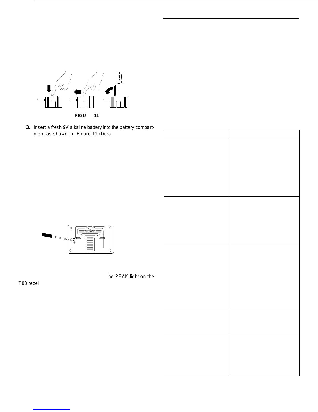
2. Press down on the OPEN side of the battery compart-
ment cover, slide it back and flip it open, as shown in Fig-
ure 11.
Á
Á
Á
Á
Á
Á
+-
Á
Á
Á
Á
Á
Á
Á
Á
Á
Á
Á
Á
Á
ÁÁ
Á
Á
Á
Á
Á
Á
Á
Á
Á
Á
Á
ÁÁÁ
Á
Á
Á
Á
Á
Á
Á
Á
Á
Á
Á
Á
Á
Á
Á
Á
Á
ÁÁ
ÁÁ
Á
Á
Á
Á
Á
Á
Á
Á
Á
Á
Á
ÁÁÁ
Á
Á
Á
Á
Á
Á
Á
Á
Á
Á
Á
Á
Á
Á
Á
Á
ÁÁ
Á
Á
Á
Á
Á
Á
Á
Á
Á
ÁÁÁ
Á
Á
Á
Á
FIGURE 11
3. Insert a fresh 9V alkaline battery into the battery compart-
ment as shown in Figure 11 (Duracell MN1604 recom-
mended and included with the system). A fresh 9V alkaline
battery should typically provide 18 hours of performance
time. A fully charged 8.4V NiCad battery should provide
2 hours of performance time. When the red LOW BAT-
TERY light on the transmitter glows, you have 1 hour or
less of useful battery life remaining; change the battery
at your first opportunity.
IMPORTANT: Carbon-zinc and zinc-chloride batteries will not
provide adequate power and are not recommended.
4. Replace the battery cover.
Transmitter audio gain adjustment
FIGURE 12
Á
Á
Á
Á
Á
Á
Á
Á
Á
Á
Á
Á
Á
Á
Á
Á
Á
Á
Á
Á
Á
Á
ÁÁÁÁÁÁÁ
The transmitter audio gain control has been factory preset to
provide satisfactory output. However, if the PEAK light on the
T88 receiver is constantly on or never on, the transmit audio lev-
el may require adjustment. Use the gain controls as follows to
adjust the equipment for the best sound quality.
To adjust the audio gain, locate the transmitter audio gain con-
trol and use the supplied screwdriver to adjust the control.
•If the PEAK light is always on, decrease the audio gain by turn-
ing the gain control counter-clockwise (while the vocalist is
singing or the musical instrument is being played) until the
PEAK light on the receiver flickers only occasionally.
•If the PEAK light is never on, increase the audio gain by turning
the gain control clockwise (while the vocalist is singing or the
musical instrument is being played) until the PEAK light on the
receiver flickers only occasionally.
TIPS AND TROUBLESHOOTING
Tips for getting the best performance
•Maintain a line-of-sight between the transmitter and receiver
antennas.
•Keep the receiver and antennas away from large metal ob-
jects.
•Avoid placing the receiver near computers or other RF gener-
ating equipment.
•Point the receiver antennas straight up.
•Avoid placing the receiver in the bottom of an equipment rack
unless the antennas are remotely located.
Troubleshooting
Some common problems and their solutions are identified in
the table below. If you are unable to solve a problem, contact your
dealer.
Problem Solution
No sound; RF light(s)
not glowing. •Make sure the transmitter
POWER switch is ON and the re-
ceiver is plugged into a power
source.
•Check battery.
•Check receiver squelch setting.
•Check receiver antenna connec-
tion(s).
•Make sure antennas are in line of
sight of transmitter.
No sound; RF and Audio Level
meter lights glowing. •Turn up receiver audio VOLUME
control.
•Check for proper connection be-
tween receiver and karaoke unit.
•Talk into microphone and ob-
serve receiver audio level lights.
If they glow, the problem is else-
where in the sound system.
Received signal is noisy or con-
tains extraneous sounds with
transmitter on.
•Check battery.
•Remove local sources of RF inter-
ference.
•If using a guitar or other instru-
ment, check connections.
•Two transmitters may be operating
on the same frequency. Locate
and turn one off.
•Signal may be too weak. Reposi-
tion antennas. If possible, move
them closer to transmitter.
Noise from receiver with trans-
mitter off. •Adjust receiver squelch control.
•Remove local sources of RF inter-
ference.
•Reposition receiver or antennas.
Momentary loss of sound as
transmitter is moved around
performing area.
•Reposition receiver and perform
another “walkthrough” test and
observe the RF indicators. If au-
dio dropouts persist, mark these
“dead spots” in performing area
and avoid them during perfor-
mance.

6
English –
SPECIFICATIONS AND INFORMATION
Specifications
RF Carrier Frequency Range
169.445 to 216.000 MHz
Working Range
100 m (approximately 300 ft) under typical conditions.
Audio Frequency Response
50 to 15,000 Hz, ±2 dB.
Audio Output Level (±15 kHz deviation, 1 kHz tone)
1/4–inch connector (into 3 kΩload):–8.8 dBV (Hi Z)
Audio Connectors
Model: T88 T1
Connector
Type: 1/4-inch
phone plug
(female)
4-Pin miniature
connector
(TA4F)
Configuration: active
unbalanced active
unbalanced
Actual
Impedance: 3 kΩ18 kΩ
with lavalier
Maximum
Input Level: —12.2 dBu
Maximum
Output Level: 0 dBu —
Pin
Assignments: Tip = hot
sleeve = ground
pin 1= ground
pin 2 = +5 V
pin 3 = audio
pin 4 = through
20 kΩresistor
to ground
Phantom Power
Protection: yes —
Voltage: —+5 V
27 pF
20K Ω
27 pF
+5 V
AUDIO
GROUND
T1 MIC JACK BOARD
2
1
4
500 Ω
500 Ω
MICROPHONE
ELEMENT
3
2
1
3
4
NOTE: LAVALIER MIC TIES PINS 3 AND 4 TOGETHER; GUITAR CABLE DOES NOT.
T1 Pin Connections
T88 Output Wiring (1/4-in. male plug to output connector)
SLEEVE
TIP +
Gain Adjustment Range
T1: 40 dB
T2/14A: 25 dB
RF Power Output
T1, T2/14A: 50 mW maximum (complies with FCC and IC
regulations)
RF Sensitivity
–101 dBm, typical
System Distortion (ref. ±15 kHz deviation, 1 kHz modulation)
0.7%
Power Requirements
T1, T2/14A: 9V alkaline battery (Duracell MN1604 recom-
mended). 8.4V Nicad (rechargeable) are optional but not
recommended.
T88: 12 Vdc (PS20, 120Vac; PS20E, 230 Vac Power Supply)
Current Drain
T1: 31 mA average (40 mA max), T2/14A: 30 mA average (35
mA max)
T88: 160 mA average (195 mA max)
Operating Temperature Range
-20°to 50°C (-4°to 122°F). NOTE: Battery characteristics
may limit this range.
Overall Dimensions
T1: 82.6 mm H x 63.5 mm W x 26.2 mm D
T2/14A: 241 mm L x 50.8 mm Dia.
T88: 44 mm H x 349 mm W x 194mm D
Net Weight
T1: 79.5 g without battery
T2/14A: 294.8 g without battery
T88: 435 g
Certification
T1, T2: Type-accepted under FCC Parts 90 and 74; IC certi-
fied under TRC-78
T88: Approved under the Notification provision of
FCC Part 15
PS20 Power Supply: Conforms to safety standard UL1310.
Canada/CSA 22 2 No. 223.
PS20E Power Supply: Conforms to safety standard EN 60065
PS20UK Power Supply: Conforms to safety standard EN
60065.
Furnished Accessories
Plastic Screwdriver 65A1659. . . . . . . . . . . . . . . . . . . . . . . . . . . .
Swivel Adapter (hand-held only) WA370A. . . . . . . . . . . . . . . . .
Anti-Roll Device (hand-held only) 66A8043. . . . . . . . . . . . . . . .
Optional Accessories
Microphone Adapter Cable (T1) WA310. . . . . . . . . . . . . . . . . .
4-Pin Female Mini Connector TA4F (T1) WA330. . . . . . . . . . .
In-Line Audio Switch (T1) WA360. . . . . . . . . . . . . . . . . . . . . . . .
1.8 Meter (6 ft.) Receiver-Mixer Cable WA410. . . . . . . . . . . . .
6.1 Meter (20 ft.) Antenna Extension Cable WA421. . . . . . . .
Replacement Parts
14A Cartridge with Grille R200. . . . . . . . . . . . . . . . . . . . . . . . . . .
AC Adapter PS20 (120 Vac)/PS20E (230 Vac). . . . . . . . . . . . .
Grille (T2/14A) RK143G. . . . . . . . . . . . . . . . . . . . . . . . . . . . . . . .
Belt Clip (T1) 53A8247A. . . . . . . . . . . . . . . . . . . . . . . . . . . . . . . .
1/4-Wave Antenna 90A8380. . . . . . . . . . . . . . . . . . . . . . . . . . . . .

7
English –
Licensing Information
Changes or modifications not expressly approved by Shure
Inc. could void your authority to operate the equipment. Licens-
ing of Shure wireless microphone equipment is the user’s re-
sponsibility, and licensability depends on the user’s classifica-
tion and application, and on the selected frequency. Shure
strongly urges the user to contact the appropriate telecommu-
nications authority concerning proper licensing, and before
choosing and ordering frequencies other than standard frequen-
cies.
Warranty Information
Shure Incorporated (“Shure”) hereby warrants that these
products will be free from defects in material and workmanship
for a period of one year from the date of purchase. At its option,
Shure will repair or replace the defective product and promptly
return it to you, or refund the purchase price. Retain proof of pur-
chase to validate the purchase date and return it with any war-
ranty claim. If you believe this product is defective within the
warranty period, carefully repack the unit, insure it, and return it
postpaid to: Shure Incorporated
Attention: Service Department
222 Hartrey Avenue
Evanston, IL 60202-3696 U.S.A.
Telephone: (847) 866-5730
For service outside the United States, return the product to
any authorized Shure Distribution Center.
All claims of defects or shortage should be directed to the
above address. Please furnish model number, operating fre-
quency, and date, place and proof of purchase (such as a copy
of your sales receipt) to establish warranty. Your letter should
include all pertinent details including applicable model or part
numbers and a brief description of the problem. Do not mail any
units or parts to Shure unless requested to do so by Shure’s Ser-
vice Department. Any returned items must have prior authoriza-
tion. Unauthorized returns are delayed in handling; these de-
lays can be avoided by contacting Shure in advance and furnish-
ing the necessary information.
Shure reserves the right to make design changes and product
improvements on any previously manufactured products.
Shure also reserves the right to ship new and/or improved prod-
ucts which are similar to the form, fit and function of the originally
ordered products.

SHURE Incorporated Web Address: http://www.shure.com
222 Hartrey Avenue, Evanston, IL 60202–3696, U.S.A.
Phone: 847-866–2200 Fax: 847-866-2279
In Europe, Phone: 49-7131-72140 Fax: 49-7131-721414
In Asia, Phone: 852-2893-4290 Fax: 852-2893-4055
Elsewhere, Phone: 847-866–2200 Fax: 847-866-2585
Table of contents
Other Shure Microphone System manuals

Shure
Shure PA421B User manual

Shure
Shure PSM400 Wireless Personal User manual

Shure
Shure UHF-R Wireless User manual

Shure
Shure SLX-D User manual

Shure
Shure 404B User manual

Shure
Shure UHF-R Wireless User manual

Shure
Shure PSM 900 User manual

Shure
Shure SCM410 User manual

Shure
Shure BLX4R User manual

Shure
Shure ULX-D Programming manual

Shure
Shure PGXD User manual

Shure
Shure ULX Wireless System Owner's manual

Shure
Shure PGX Wireless System User manual

Shure
Shure KCX User manual

Shure
Shure GLXD Plus FM User manual

Shure
Shure R2 Owner's manual

Shure
Shure ULXD-G51 User manual

Shure
Shure FP Wireless User manual

Shure
Shure PSM 900 User manual

Shure
Shure PG Wireless User manual