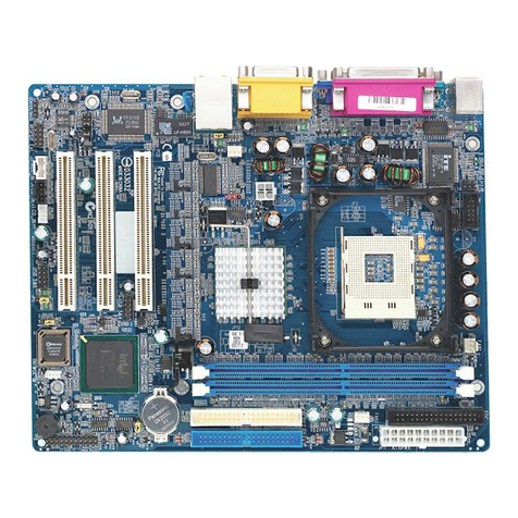
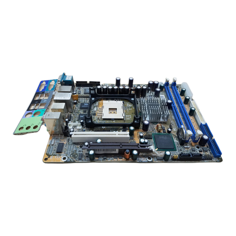
Shuttle MV43P User manual

MV43P/MV43PN
Pentium 4 Processor
Based DDR/SDR MAIN BOARD
User's Manual

Shuttle®MV43P/MV43PN
Pentium 4/Celeron , 478-pin processor based DDR Mainboard
Manual Version 1.0
Copyright
Copyright©2003 by Shuttle®Inc. All Rights Reserved.
No part of this publication may be reproduced, transcribed, stored in a retrieval system,
translated into any language, or transmitted in any form or by any means, electronic,
mechanical, magnetic, optical, chemical, photocopying, manual, or otherwise, without
prior written permission from Shuttle®Inc.
Disclaimer
Shuttle®Inc. shall not be liable for any incidental or consequential damages resulting from the
performance or use of this product.
This company makes no representations or warranties regarding the contents of this manual.
Information in this manual has been carefully checked for reliability; however, no guarantee is
given as to the correctness of the contents. In the interest of continued product improvement,
this company reserves the right to revise the manual or include changes in the specifications
of the product described within it at any time without notice and without obligation to notify any
person of such revision or changes. The information contained in this manual is provided for
general use by the customers.
Trademarks
Shuttle is a registered trademark of Shuttle Inc.
Intel Pentium is a registered trademarks of Intel Corporation.
VIA is a registered trademarks of VIA Corporation.
PS/2isaregisteredtrademarkofIBMCorporation.
AMIisaregisteredtrademarkofAMISoftwareInc.
MicrosoftandWindowsareregisteredtrademarksofMicrosoftCorporation.
General Notice: Other product names used in this manual are ascribed to their respective
owners and acknowledged.
M756

Statement of Shuttle Mainboard via the EMI Test
Shuttle mainboards have been via the EMI test in terms of series of regulations: EN55022/
CISPR22/AS/NZS3548ClassB, EN55024 (1998/AS/NZS), EN4252.1 (1994), EN61000,ANSI
C63.4 (1992), CFR47 Part 15 Subpart B, and CNS13438 (1997). The items tested are illus-
trated as follows:
(A)Voltage:AC110V/60HZ &AC230V/50HZ
(B) Tested Product Information:
Product Name: PC Mainboard
Status: Sample
ModelName: MV43PN
S/N:N/A
CPU:
External Frequency: 133 MHz
IntelPentium4:1.6GHz/1.7GHz/2.2GHz/2.4GHz/2.53GHz/ 2.8GHz/ 3.06GHz
External Frequency: 100 MHz
IntelPentium4:1.4GHz/ 1.5GHz/ 1.6GHz/ 1.7GHz/ 1.8GHz/ 1.9GHz/ 2GHz/
2.2GHz/ 2.4GHz
Keyboard Port: one port with 6 pins
Mouse Port: one port with 6 pins
USB 2.0 Port: Four ports with 4 pins respectively
Parallel Port: One port with 25 pins
Serial Port: One ports with 9 pins respectively
LAN Port: One port with 8 pins
Line-Out & Line-In & Mic-In Ports: one port for each
DDR Memory: 256 MB *2
All CPUs have completely been tested, and values offered by the worst EMI combination of
CPU external frequency are listed as follows:
(C) Remedy for the Tested Product & Its EMI Interference:
Remedy:N/A
EMIInterference:
Crystal:32.768 KHz(X1)/14.318 MHz(X3)/24.576 MHz(X4)/25MHz(X5)
Clock Generator: U6
Test Mode External Frequency CPU Power Supply Case Open/Closed
1133MHz Pentium 43.06GHz Closed
2133MHz Pentium4 3.06GHz Open
3100MHz Pentium4 2.4GHz Closed
4100MHz Pentium4 2.4GHz Open

(D) Supported Host Peripherals:
Host Peripheral Product Name Model Name S/N FCC ID
#1 Case KF45A N/A
#2 Power Supply (300W) ENP-0730 (ATX12V) 100002885
#3 IBM HDD (30.7GB) 91024UB YKFY7981 3892I168
#4 MITSUMI FDD D353M
#5 ASUS VCD Player CD-S500/A 0524CIH4113070-2
#6 Power Cable Detachable and Shielded

- 1 -
WHAT'S IN THE MANUAL.................................................................... 5
Quick Reference............................................................................................... 5
About This Manual ........................................................................................... 5
1 INTRODUCTION................................................................................ 6
1.1 TO DIFFERENT USERS ............................................................................. 6
FIRST-TIMEDIYSYSTEMBUILDER............................................................ 6
EXPERIENCEDDIY USER ........................................................................ 6
SYSTEMINTEGRATOR............................................................................... 6
1.2 ITEM CHECKLIST: ...................................................................................... 7
2 FEATURES ........................................................................................ 8
2.1 SPECIFICATIONS ....................................................................................... 8
3 HARDWARE INSTALLATION.......................................................... 11
3.1 STEP BY STEP INSTALLATION................................................................11
Accessories of MV43P/MV43PN...........................................................11
STEP1 Installthe CPU.......................................................................... 12
STEP 2 Set Jumpers............................................................................. 14
STEP 3 InstallDDR or SDR SDRAM SystemMemory ........................... 14
STEP4 InstallPeripherals in SystemCase............................................ 15
STEP5 Mountthe Mainboardon theComputer Chassis........................ 16
STEP6 ConnectFrontPanel Switches/LEDs/Speaker/USB.................. 17
STEP 7 Connect IDE and Floppy Disk Drives........................................ 18
STEP8Connect OtherInternalPeripherals............................................ 18
STEP9 Connectthe PowerSupply........................................................ 19
STEP10 InstallAdd-onCards in ExpansionSlots .................................. 20
STEP11 Connect External Peripherals toBack Panel .......................... 21
STEP 12 First Time System Boot Up ..................................................... 22
STEP13 InstallDrivers & SoftwareComponents ................................... 23
TABLE OF CONTENTS
- 2 -
3.2 JUMPER SETTINGS ................................................................................. 24
JUMPERS& CONNECTORSGUIDE.................................................... 25
Jumpers
Clear CMOS Setting (JBAT1) ............................................................... 28
CPU Clock Setting (JP1A1/JP1B1)....................................................... 28
DRAM Voltage Setting (JP1) ................................................................. 29
DDR/SDRDRAMType Selector(J2A/B/C/D,J3A/B/C/D) ....................... 29
KeyboardPower On(JP2)...................................................................... 30
Back-Panel Connectors
PS/2Keyboard & PS/2Mouse Connectors............................................ 31
ParallelPortConnector.......................................................................... 31
COM1Port Connector ........................................................................... 31
VGAPortConnector .............................................................................. 31
USB1/USB2Port Connectors................................................................ 31
LANPortConnector(MV43PN only) ....................................................... 32
USB3/USB4Port Connectors................................................................ 32
Line-InPortConnector ........................................................................... 32
Line-OutPortConnector ........................................................................ 32
Mic-InPortConnector ............................................................................ 32
Front-Panel Connectors
HDD LED Connector(HD_LED) ............................................................ 33
GreenLED Connector (SP_LED).......................................................... 33
HardwareResetConnector (RST) ......................................................... 34
ATXPowerOn/Off SwitchConnector(PW_BN) ..................................... 34
SpeakerConnector (SPK1)................................................................... 34
SleepSwitch (J12) ................................................................................ 35
LANLED Indicator(J16)........................................................................ 35
ExtendedUSB Header (USB2).............................................................. 35

- 3 -
Internal Peripherals Connectors
EnhancedIDE and FloppyConnector ................................................... 36
Other Connectors
ATX PowerSupply Connectors(CN5/PJ1) ............................................. 37
CPU& SystemFanConnectors (CPU-FAN,SYSTEM-FAN).................. 38
Wake-onLanConnector (WOL1)........................................................... 38
Wake-onModemConnector (WOM1) .................................................... 39
SerialinfraredPort (SIR1)....................................................................... 39
Audio Cable Header (CD1/CD2)........................................................... 40
Front-PanelMicrophone andLine_outHeader (PANEL1) ...................... 40
3.3 SYSTEM MEMORY CONFIGURATION ..................................................... 41
1.INSTALLMEMORY............................................................................ 41
2.UPGRADEMEMORY ........................................................................ 41
4 SOFTWARE UTILITY ......................................................................42
4.1 Mainboard CD Overview ......................................................................... 42
4.2 Install Mainboard Software Driver .......................................................... 43
4.2AInstallVIA ChipsetDriver................................................................ 44
4.2BInstallVGA Driver .......................................................................... 45
4.2CInstallAudio Driver......................................................................... 46
4.2DInstall USB2.0Driver ..................................................................... 47
4.2EInstallLAN Driver(MV43PNonly) ................................................... 48
4.3 View the User's Manual.......................................................49
5 BIOS SETUP ................................................................................... 50
5.1 ENTER BIOS ............................................................................................. 50
5.2 THE MAIN MENU ...................................................................................... 51
STANDARD CMOS SETUP ...................................................................... 53
ADVANCED SETUP ................................................................................. 55

- 4 -
POWERMANAGEMENT SETUP.............................................................. 59
PCI/PLUGAND PLAYSETUP ................................................................... 61
LOADOPTIMALSETTING ........................................................................ 62
LOADBEST PERFORMANCESETTING.................................................. 62
FEATUNESSETUP .................................................................................. 63
CPU PNP SETUP ..................................................................................... 66
HARDWAREMONITOR............................................................................. 67
CHANGEPASSWORD ............................................................................. 68
EXIT .......................................................................................................... 69

- 5 -
Quick Reference
Hardware Installation >> Step-by-Step ................................................ Page 11
Jumper Settings >> A Closer Look ......................................................Page 24
Drivers/Software Utilities >> How to Install .........................................Page 42
BIOS Setup >> How to Configure.........................................................Page 50
About This Manual
For First-Time DIY System Builder.........................................................Page 6
For Experienced DIY User ......................................................................Page 6
For System Integrator .............................................................................Page 6
WHAT'S IN THE MANUAL

- 6 -
1.1 To Different Users
First-Time DIY System Builder
Welcome to the DIY world! Building your own computer system is not as diffi-
cult as you may think. To make your first computer DIY experience successful,
right from the start, we have designed the 3.1 Hardware Installation section
in a step-by-step fashion for all the first-time DIY system builders. Prior to instal-
lation, we also suggest you to read the whole manual carefully to gain a com-
plete understanding of your new Shuttle MV43P/MV43PN mainboard.
Experienced DIY User
Congratulate on your purchase of the Shuttle MV43P/MV43PN mainboard.
You will find that installing your new Shuttle MV43P/MV43PN mainboard is
just easy. Bundled with an array of onboard functions, the highly-integrated
MV43P/MV43PN mainboard provides you with a total solution to build the
most stable and reliable system. Refer to sections 3.2 Jumper Settings and
Chapter 4 Drivers/Software Utilities to find out how to get the best out of
your new mainboard. Chapter 5 BIOS Setup also contains the relevant infor-
mation on how to tune up your system to achieve higher performance.
System Integrator
You have wisely chosen Shuttle MV43P/MV43PN to construct your system.
Shuttle MV43P/MV43PN incorporates all the state-of-the-art technology of the
P4 M266A chipset from VIA. It integrates the most advanced functions you can
find to date in a compact Micro ATX board.
1INTRODUCTION
This mainboard adopted in MV43P and MV43PN mainboards at the same time.
The difference between MV43 and MV43PN is that MV43PN equips with
onboard VIA VT6103 LAN PHY. In the manual, if there are some standards,
characters, equipment or software only appeared or adopted by MV43PN; it
will be mentioned(MV43PN only).

- 7 -
1.2 Item Checklist:
Check all items with your MV43P/MV43PN mainboard to make sure nothing
is missing. The complete package should include:
-One piece of Shuttle MV43P/MV43PN Mainboard
-One piece of ATA 133/100/66/33 Ribbon Cable
-IO Shielding
-One piece of Floppy Ribbon Cable
-One piece of twin ports USB Cable (optional)
-MV43P/MV43PN User's Manual
-One piece of Bundled CD-ROM with containing:
ØMV43P/MV43PN user's manual saved in PDF format
ØVIA Chipset System Driver
ØVIA VGA Driver
ØOnboard Audio controller driver
ØAMI Flashing Utility
ØLAN Driver (MV43PN Only)
ØUSB2.0 Driver
22144Q12124
RTM360-107R
9
3
7
1
8
C
F
R
T
M
6
8
0
-
2
5
5
R
KB_MS
COM1
COM2 PRT
CD1
CD2
IDE1
IDE2
FDC
CN5
R
G
8
2
84
5
Q
C
2
2
E
S
CNR1
PCI1
PCI2
J
P
2
SIR1
J12
J
1
6
JBAT1
11
1
SPK1
PANEL1
USB2
1
1
WOL1
WOM1
VT8235
0302CD TAIWAN
23A3985941
PCI1
IT8705F
0232-FXS
Mf5920
CR2032
JAPANSTD
LITHIUMBATTERY
K T S
A
G
P
1
PANEL2
1
2
SYSTEM_FAN
C
P
U
_
F
A
N
USB1
LINE1

- 8 -
MV43P/MV43PN mainboard is carefully designed for the demanding PC user who wants
high performance and maximum Intelligent features in a compact package.
2.1 Specifications
-CPU Support
Intel Pentium 4, 478-pin processors with 400/533 MHz FSB.
-Chipset
Features VIA P4M266A N.B. and VIA VT8235 S.B..
-Integrated Graphics Controller
P4M266A integrates S3Savag4 TM graphics accelerator into a single chip.
P4M266A brings mainstream graphics performance to the Value PC with
leading-edge 2D, 3D and DVD video acceleration into a cost effective
package. Based on its capabilities, P4M266A is an ideal solution for the
consumer, corporate mobile users and entry-level professionals.
Maximum-shared memory size is 32MB.
-Built-in Ethernet LAN (MV43PN only)
Built-in 10BaseT/100BaseTX Ethernet LAN.
VT8233 integrates Fast Ethernet MAC and VT6103 LAN PHY in compliance
with IEEE802.3u 100BASE-TX, 10BASE-T and ANSI X3.263 TP-PMD stan-
dards.
In compliance with ACPI 1.0 and the Network Device Class Power Manage-
ment 1.0.
High performance achieved by 100Mbps clock generator and data recovery
circuit for 100Mbps receiver.
-AC'97 Audio Codec
AC'97 2.1 compliant.
Spread independent PCI functions for Audio and Modem.
-Versatile Memory Support
Two 184-pin DIMM slots to support up to 2GB of PC1600 or PC2100
compliant DDR SDRAM module.
or two 168-pin DIMM slots to support up to 2GB of PC100 or PC133
compliant SDR SDRAM module.
-PCI Expansion Slots
Provides two 32-bit PCI slots.
2 FEATURES

- 9 -
-AGP Expansion Slots
Provides one 32-bit AGP slot which supports 4X AGP devices.
-CNR Expansion Slot
Provides one CNR (Communication/ Network Riser) slot.
-6 USB 2.0 Interface Onboard
Ø4 USB connectors on back-panel and one set of dual USB ports headers
on mid-board.
-I/O Interface
Provides a variety of I/O interfaces:
Ø1* Floppy interface for 3.5-inch FDD with 720KB, 1.44MB, or 2.88MB
format or for 5.25-inch FDD with 360K or 1.2MB format.
Ø1*PS/2 mouse connector.
Ø1*PS/2 Keyboard connector.
Ø1*RJ45 LAN connector.(MV43PN only)
Ø1*DB9 serial connector 16550 UART compatible.
Ø4*USB ports.
Ø1*VGA port.
Ø1*DB25 Parallel port supports Standard Parallel Port and Bi-directional
(SPP), Enhanced Parallel Port (EPP), and Extended Capabilities Port
(ECP) data transmission schemes.
Ø1*Line-Out port.
Ø1*Line-In port.
Ø1*Mic-In port.
-PCI Bus Master IDE Controller Onboard
Two Ultra DMA 133/100/66/33 Bus Master Dual-channel IDE ports provide
support to a maximum of four IDE devices (one Master and one Slave per chan
The IDE Bus implements data transfer speeds of up to 133/100 /66/33 MB/
sec and also supports Enhanced PIO Modes.
80-pin Cable Backward Compatible Legacy ATAPI Devices, ATAPI IDE CD-
ROM, CD-R, CD-RW, and LS-120 Supports.nel).
-ATX Power Supply Connector
ATX power supply unit can connected to the onboard 20-pin Pentium 4
standard ATX power connectors, supporting Suspend and Soft-On/Off by
dual-function power button.
The Pentium 4 ATX power include one 4-pin+12V ATX power connector.

- 10 -
-Advanced Configuration and Power Interface
Features four power saving modes: S1 (Snoop), S4 (Suspend to DISK), and S5
(Soft-Off). ACPI provides more efficient Energy Saving Features controlled by
your operating system that supports OS Direct Power Management (OSPM)
functionality.
-System BIOS
Provides licensed AMI BIOS 2Mb Flash core and supports Green PC, Desk-
top Management Interface (DMI).
-Micro ATX Form Factor
System board conforms to Micro ATX specification.
Board dimension: 244mm*244mm.
-Advanced Features
ØLow EMI - Built in spread spectrum and automatic clock shut-off of
unused PCI/SDRAMS slots to reduce EMI.
ØDual Function Power Button - The system can be in one of two states,
one is Suspend mode and the other is Soft-Off mode. Pushing the power
button for less than 4 seconds places the system into Suspend mode.
When the power button is pressed for longer than 4 seconds, the system
enters Soft-Off mode.
ØModem Ring Power-On - The system can be powered on automatically by
the activation of modem ringing.
ØCPU Clock Setting - This item allows users to adjust CPU Host Clock in
BIOS.
ØCPU Multiplier Setting - This item allows users to adjust CPU Multiplier in
BIOS.
-Intelligent Features
ØVoltage Monitoring -Monitors various voltages of key elements, such
as the CPU, and other critical system voltage levels to ensure stable
current passing through mainboard components.
ØFan Status Monitoring -To prevent CPU from overheating, the CPU fan
is monitored for RPM and failure. (CPU Cooling FAN with RPM sensor
is required.)
ØTemperature Monitoring -This item allows users to make sure whether
the CPU or system runs in a suitable temperature.

- 11 -
Before removing or installing any of these devices including CPU, DIMMs,
Add-On Cards, Cables, please make sure to unplug the onboard power
connector.
This section outlines how to install and configure your mainboard. Refer to the following
mainboard layout to help you to identify various jumpers, connectors, slots, and ports.
Then follow these steps designed to guide you through a quick and correct installation of
your system.
3.1 Step-by-Step Installation
3HARDWAREINSTALLATION
Accessories Of MV43P/MV43PN
Two PCI Slots
One AGP 4x Slot
One CNR Slot
Extended USB header- USB2
Keyboard Power On- JP2
Wake on LAN-WOL1
Speaker Connector-SPK1
System FAN
Wake on Modem-WOM1
USB & LAN(MV43PN only)
Ports
Parallel Connector(LPT1)
Serial Port
Connector (COM1)
Panel1 Connector
Panel2 Connector
Serial infrared port-SIR1
Line-Out/Line-In/Mic-In/
Ports
Onboard Audio
Connectors- CD1/CD2
PS/2 Keyboard and
PS/2 Mouse Connectors
CPU Clock - JP1A1/ JP1B1
CPU FAN
ATX Power Connector
Clear CMOS - JBAT1
Sleep Switch-J12
TwoE-IDEConnectors
V
I
A
8
2
3
5
C
h
i
p
s
e
t
USB Ports
Two168pinSDRDIMM Slots
DRAMVoltage-JP1
Two184pinDDRDIMM Slots
DDR/SDRDRAMTypeSelector
-
J
2
A
/
B
/
C
/
D
J
3
A
/
B
/
C
/
D
/
Socket 478
VIA P4 M266A Chipset
VGA Port
ATX Power Connector
Floppy Connector
Onboard LAN LED connector-
J16
22144Q1 2124
RTM360-107R
9
3
7
1
8
C
F
R
T
M
6
8
0
-
2
5
5
R
KB_MS
COM1
COM2 PRT
CD1
CD2
IDE1
IDE2
FDC
CN5
R
G
8
2
8
4
5
Q
C
2
2
E
S
CNR 1
PCI1
PCI2
J
P
2
SIR1
J12
J
1
6
JBAT1
11
1
SPK1
PANEL1
USB2
1
1
WOL1
WOM1
VT8235
0302CD TAIWAN
23A3985941
PCI1
IT8705F
0232-FXS
Mf5920
CR2032
JAPAN STD
LITHIUM BATTERY
K T S
A
G
P
1
PANEL2
1
2
SYSTEM_FAN
C
P
U
_
F
A
N
USB1
LINE1

- 12 -
Step 1
CPU Installation:
This mainboard supports Intel Pentium 4, Socket 478 series CPU. Please
follow the step as below to finish CPU installation.
Be careful of CPU orientation when you plug it into CPU socket.
1. Pull up the CPU socket lever and up to 90-degree angle.
2. Locate Pin 1 in the socket and look for a black dot or cut edge on the
CPU upper interface. Match Pin 1 and cut edge, then insert the CPU
into the Socket.
CPU pin 1 and cut edge
CPU socket lever up to
90 degree

- 13 -
3. Press down the CPU socket lever and finish CPU installation.
Note: If you do not match the CPU socket Pin 1 and CPU cut edge
well, it may damage the CPU.
4. The Intel Pentium 4 /Celeron processor requires a set of heatsink/fan to en
sure proper cooling of the processor. If heatsink/fan have not been already
bundled with your CPU, you must purchase the heatsink/fan separately and
have it installed. Plug the cable through the heatsink/fan in the CPU fan
power connector located nearby. Note that there are several types of CPU
fan connectors. Normally, if your mainboard supports the hard ware moni
toring function, a 3-pin fan power connector should allow your system to
detect the CPU fan's speed. The CPU fan can also run with a 2-pin fan
power connector, however, detection of CPU fan's speed is not supported.
Another type of CPU fan may feature a large 4-pin fan power connector,
which does not support CPU fan's speed detection and must be directly
connected to the system's power supply unit.

- 14 -
Step 2.
Set Jumpers
The default jumper settings have been set for the common usage standard of
this mainboard. Therefore, you do not need to reset the jumpers unless you
require special adjustments as any of the following cases:
1. Clear CMOS
2. CPU Clock Setting
3. DRAM Voltage Setting
4. DDR/SDR DRAM Type
5. Keyboard power on Setting
For first-time DIY system builders, we recommend that you do not change the
default jumper settings if you are not totally familiar with the mainboard
configuration procedures. The factory-set default settings are tuned for opti-
mum system performance. For the advanced users who wish to customize
their system, section 3.2 Jumper Settings will provide detailed information
on how to configure your mainboard manually.
Step 3
Install DDR or SDR SDRAM System Memory
To insert memory module(s) in any one or two DIMM slot(s). Please note that
modules are directional and will not go in the DIMM slots unless properly
oriented. After the module is fully inserted into the DIMM slots, lift the clips
of both sides of the DIMM slot to lock the module in place.
SDR SDRAM DDR SDRAM

- 15 -
Step 4
Install Internal Peripherals in System Case
Before you install and connect the mainboard into your system case, we
recommend that you first assemble all the internal peripheral devices into the
computer housing, including but not limited to the hard disk drive (IDE/
HDD), floppy disk drive (FDD), CD-ROM drive, and ATX power supply
unit. This will greatly facilitate in making the connections to the mainboard
described below.
To install IDE & FDD drives, follow this procedure:
1. Set the required jumpers on each device according to the instructions
provided by the manufacturer. (IDE devices, HDD, and CD-ROM, have
to set jumpers to Master or Slave mode depending on whether you install
more than one device of each kind.)
2. Connect IDE cable and FDD cable on the back-panel of the internal
peripheral devices to the corresponding headers on board. Note that
the cable should be oriented with its colored stripe (usually in red or
magenta) connected to pin#1 both on the mainboard IDE or FDD
connector and on the device as well.
3. Connect an available power cable from your system power supply unit
to the back-panel of each peripheral device. Note that the power cable
is directional and cannot fit in if not properly positioned.

- 16 -
Step 5
Mount the Mainboard on the Computer Chassis
1. You may find that there are a lot of different mounting hole positions
both on your computer chassis and on the mainboard. To choose
correct mounting holes, the key point is to keep the back-panel of the
mainboard in a close fit with your system case, as shown below.
2. After deciding on the proper mounting holes, position the studs be
tween the frame of the chassis and the mainboard. The studs are used
to fix the mainboard and to keep a certain distance between the system
chassis and the mainboard, in order to avoid any electrical shorts between
the board and the metal frame of the chassis. (If your computer case is
already equipped with mounting studs, you will need to tighten screws to
attach the mainboard.)
Note:
1. In most computer housings, you will be able to find 4 or more attachment
points to install mounting studs and then fix the mainboard. If there aren't
enough matching holes, then make sure to install at least 4 mounting
studs to ensure proper attachment of the mainboard.
2. There are two rubber pads attached on the solder-side of the mainboard. It
prevents the mainboard damaged by the improper force while installing
devices such as IDE cable, DIMM modules. You may also move the
rubber pad's position varies with your chassis design.
This manual suits for next models
1
Table of contents
Other Shuttle Motherboard manuals

Shuttle
Shuttle HOT-641/P User manual

Shuttle
Shuttle MS52P User manual

Shuttle
Shuttle HOT-661Z User manual

Shuttle
Shuttle MV43V User manual

Shuttle
Shuttle AB60/R User manual

Shuttle
Shuttle HOT-565 User manual

Shuttle
Shuttle MZ11 User manual

Shuttle
Shuttle AK32E User manual

Shuttle
Shuttle AK35GT User manual

Shuttle
Shuttle Spacewalker MV17 User manual

Shuttle
Shuttle AB61 User manual

Shuttle
Shuttle av61 User manual

Shuttle
Shuttle FS56 User manual

Shuttle
Shuttle FN41V3 User manual

Shuttle
Shuttle HOT-675Z User manual

Shuttle
Shuttle AB52P User manual

Shuttle
Shuttle MK35 User manual

Shuttle
Shuttle HOT-433 User manual

Shuttle
Shuttle HOT-603 User manual

Shuttle
Shuttle FB75 User manual